Table of Contents
Advertisement
Quick Links
Chipsmall Limited consists of a professional team with an average of over 10 year of expertise in the distribution
of electronic components. Based in Hongkong, we have already established firm and mutual-benefit business
relationships with customers from,Europe,America and south Asia,supplying obsolete and hard-to-find components
to meet their specific needs.
With the principle of "Quality Parts,Customers Priority,Honest Operation,and Considerate Service",our business
mainly focus on the distribution of electronic components. Line cards we deal with include
Microchip,ALPS,ROHM,Xilinx,Pulse,ON,Everlight and Freescale. Main products comprise
IC,Modules,Potentiometer,IC Socket,Relay,Connector.Our parts cover such applications as commercial,industrial,
and automotives areas.
We are looking forward to setting up business relationship with you and hope to provide you with the best service
and solution. Let us make a better world for our industry!
Contact us
Tel: +86-755-8981 8866 Fax: +86-755-8427 6832
Email & Skype: info@chipsmall.com Web: www.chipsmall.com
Address: A1208, Overseas Decoration Building, #122 Zhenhua RD., Futian, Shenzhen, China
Advertisement
Table of Contents

Subscribe to Our Youtube Channel
Related Manuals for Microchip Technology dsPIC33E USB


Summary of Contents for Microchip Technology dsPIC33E USB
- Page 1 Chipsmall Limited consists of a professional team with an average of over 10 year of expertise in the distribution of electronic components. Based in Hongkong, we have already established firm and mutual-benefit business relationships with customers from,Europe,America and south Asia,supplying obsolete and hard-to-find components to meet their specific needs.
- Page 2 USB Starter Kit and PIC24E USB Starter Kit User’s Guide © 2010-2011 Microchip Technology Inc. DS51936B...
- Page 3 TSHARC, UniWinDriver, WiperLock and ZENA are trademarks of Microchip Technology Incorporated in the U.S.A. and other countries. SQTP is a service mark of Microchip Technology Incorporated in the U.S.A. All other trademarks mentioned herein are property of their respective companies.
-
Page 4: Table Of Contents
2.1 High-Level Block Diagram ................15 2.2 Features ....................... 16 Appendix A. Board Layout and Schematics A.1 Starter Kit Board Layout ................19 A.2 Application Hardware Schematics ............... 21 A.3 Starter Kit Debugger Hardware Schematics ..........26 © 2010-2011 Microchip Technology Inc. DS51936B-page 3... - Page 5 USB Starter Kit User’s Guide NOTES: DS51936B-page 4 © 2010-2011 Microchip Technology Inc.
- Page 6 Select the Help menu, and then Topics to open a list of available online help files. INTRODUCTION This chapter contains general information that will be useful to know before you use the dsPIC33E USB Starter Kit or the PIC24E USB Starter Kit. Items discussed in this Preface include: •...
- Page 7 Curly brackets and pipe Choice of mutually exclusive errorlevel {0|1} character: { | } arguments; an OR selection Ellipses... Replaces repeated text var_name [, var_name...] Represents code supplied by void main (void) user { ... DS51936B-page 6 © 2010-2011 Microchip Technology Inc.
- Page 8 Interim software releases are available at the Microchip web site. RECOMMENDED READING This user’s guide describes how to use the dsPIC33E USB Starter Kit or the PIC24E USB Starter Kit. The following documents are available and recommended as supplemental reference resources.
- Page 9 MPLAB IDE, MPLAB SIM simulator, MPLAB IDE Project Manager and general editing and debugging features. • Programmers – The latest information on Microchip programmers. These include the MPLAB PM3 device programmer and the PICkit™ 3 development programmers. DS51936B-page 8 © 2010-2011 Microchip Technology Inc.
- Page 10 2.2.4 “dsPIC33E/PIC24E USB Connectivity” • Replaced OTG with DEVICE in the Power Distribution/Switching schematic (Figure A-4) and added “Do not populate” in the USB Connections schematic (Figure A-8) in A.2 “Application Hardware Schematics” © 2010-2011 Microchip Technology Inc. DS51936B-page 9...
- Page 11 USB Starter Kit User’s Guide NOTES: DS51936B-page 10 © 2010-2011 Microchip Technology Inc.
-
Page 12: Chapter 1. Introduction
The starter kit comes preloaded with demonstration software for the user to explore the new features of the dsPIC33E DSC family (dsPIC33E USB Starter Kit) or the PIC24E MCU family (PIC24E USB Starter Kit). It is also expandable through a modular expansion interface, which allows the user to extend its functionality. -
Page 13: Starter Kit Functionality And Features
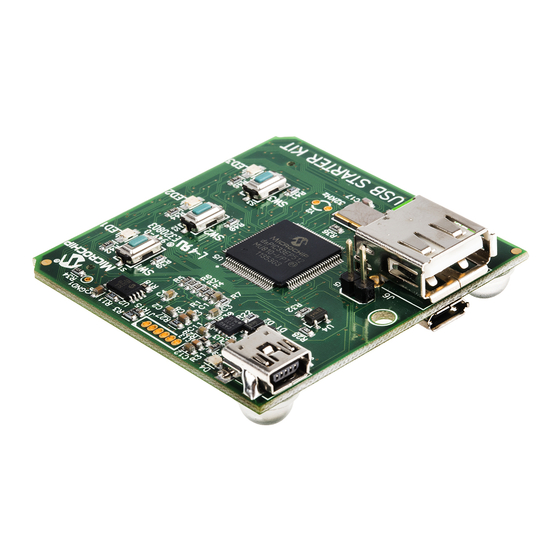
The top assembly of the board includes these key features, as indicated in Figure 1-1: 1. dsPIC33EP512MU810 16-bit DSC device (dsPIC33E USB Starter Kit) or PIC24EP512GU810 16-bit MCU (PIC24E USB Starter Kit). 2. Green power indicator LED (D4). 3. 8 MHz crystal (Y3) for precision microcontroller clocking. - Page 14 PIC24E USB device-based applications. Note: Refer to Appendix A. “Board Layout and Schematics” for details on the mapping of device pins to the pins on the expansion connector. FIGURE 1-2: STARTER KIT LAYOUT (BOTTOM SIDE) © 2010-2011 Microchip Technology Inc. DS51936B-page 13...
- Page 15 USB Starter Kit User’s Guide NOTES: DS51936B-page 14 © 2010-2011 Microchip Technology Inc.
-
Page 16: Chapter 2. Hardware
+3.3V Power or +5V_EXT Supply USB Host USB Host Power Supply (Type A) USB Device (Type mini-B) ICSP™ +5V_EXT Debugger dsPIC33EP512MU810 (PIC24FJ256GB106) (dsPIC33E USB Starter Kit) PIC24EP512GU810 (PIC24E USB Starter Kit) Switches LEDs © 2010-2011 Microchip Technology Inc. DS51936B-page 15... -
Page 17: Features
2.2.1 Processor Support The dsPIC33E USB Starter Kit is designed with a permanently mounted (i.e., soldered) dsPIC33EP512MU810 DSC. Similarly, the PIC24E USB Starter Kit is designed with a permanently mounted (i.e., soldered) PIC24EP512GU810 MCU. - Page 18 I/O Expansion Board or the Multimedia Expansion Board (MEB), thereby extending the functionality provided by the starter kit. TABLE 2-1: STARTER KIT CONNECTOR PART NUMBERS Connector HIROSE Electric P/N Starter Kit Connector FX10A-120P/12-SV1(71) Application Board Connector FX10A-120S/12-SV(71) © 2010-2011 Microchip Technology Inc. DS51936B-page 17...
- Page 19 USB Starter Kit User’s Guide NOTES: DS51936B-page 18 © 2010-2011 Microchip Technology Inc.
-
Page 20: Appendix A. Board Layout And Schematics
PIC24E USB Starter Kits and includes the following sections: • Starter Kit Board Layout • Application Hardware Schematics • Starter Kit Debugger Hardware Schematics STARTER KIT BOARD LAYOUT FIGURE A-1: STARTER KIT BOARD LAYOUT (TOP) © 2010-2011 Microchip Technology Inc. DS51936B-page 19... - Page 21 USB Starter Kit User’s Guide FIGURE A-2: STARTER KIT BOARD LAYOUT (BOTTOM) DS51936B-page 20 © 2010-2011 Microchip Technology Inc.
- Page 22 OSCO/RC15 20pF TCK/RA1 OSCIN/RC12 RF13 RF12 TDO/RPIA5 8 Mhz PMPA11//RB12 TDI/RPIA4 PMPA10/RB13 ASDA2/RA3 PMPA1/RB14 ASCL2/RA2 20pF PMPA0/RB15 D+/RG2 D-/RG3 VUSB RD14 VBUS RD15 SDA2/PMPA9/RF4 SCL2/PMPA8/RF5 USBID/RF3 dsPIC33E/24E 0.1uF 0.1uF 0.1uF 0.1uF 0.1uF 0.1uF © 2010-2011 Microchip Technology Inc. DS51936B-page 21...
- Page 23 FIGURE A-4: POWER DISTRIBUTION/SWITCHING +3.3V 100K MBR0520L FLAGB GREEN 2.2k 100K 2.2uF FPF2104 0.1uF 200k 2.2uF 0.01uF MCP1727 400mA Limit GND1...
- Page 24 Board Layout and Schematics FIGURE A-5: USER LEDs 330R 330R YELLOW 330R GREEN FIGURE A-6: USER SWITCHES © 2010-2011 Microchip Technology Inc. DS51936B-page 23...
- Page 25 USB Starter Kit User’s Guide FIGURE A-7: STARTER KIT INTERFACE DS51936B-page 24 © 2010-2011 Microchip Technology Inc.
- Page 26 FIGURE A-8: USB CONNECTIONS FLAGB FPF2100 100K 200mA Limit 100K (Do not populate) FLAGB FPF2100 100uF 100K 200mA Limit 100K...
Need help?
Do you have a question about the dsPIC33E USB and is the answer not in the manual?
Questions and answers