
Related Manuals for Microchip Technology DSPICDEM MCHV


Summary of Contents for Microchip Technology DSPICDEM MCHV
- Page 1 MCHV Development System User’s Guide 2009 Microchip Technology Inc. DS70605A Arrow.com. Downloaded from...
- Page 2 Select Mode, Total Endurance, TSHARC, WiperLock and ZENA are trademarks of Microchip Technology Incorporated in the U.S.A. and other countries. SQTP is a service mark of Microchip Technology Incorporated in the U.S.A. All other trademarks mentioned herein are property of their respective companies.
- Page 3 CAUTION – For continued protection against the risk of fire, replace the fuse with one of the same type only (i.e., Fast Act Fuse 15A/250 V). 2009 Microchip Technology Inc. DS70605A-page iii Arrow.com.
- Page 4 As the unit has no mains switch, this plug constitutes the means of disconnection from the supply and thus the user must have unobstructed access to this plug during operation. 2009 Microchip Technology Inc. DS70605A-page iv Arrow.com.
-
Page 5: Table Of Contents
Chapter 4. Hardware 4.1 Power Factor Correction (PFC) Stage Board ..........29 4.2 Power Module Stage ..................33 4.3 Electrical Specifications ................43 Appendix A. Board Layout and Schematics 2009 Microchip Technology Inc. DS70605A-page v Arrow.com. Arrow.com. Arrow.com. Arrow.com. - Page 6 MCHV Development System User’s Guide NOTES: 2009 Microchip Technology Inc. DS70605A-page vi Arrow.com. Arrow.com. Arrow.com. Arrow.com. Arrow.com. Arrow.com. Downloaded from Downloaded from Downloaded from Downloaded from Downloaded from Downloaded from...
- Page 7 MCHV Development System. • Appendix A. “Board Layout and Schematics” – This appendix provides diagrams of the hardware layout, as well as schematic diagrams for the dsPICDEM™ MCHV Development System. 2009 Microchip Technology Inc. DS70605A-page 1 Arrow.com. Arrow.com.
- Page 8 { | } arguments; an OR selection Ellipses... Replaces repeated text var_name [, var_name...] Represents code supplied by void main (void) user { ... 2009 Microchip Technology Inc. DS70605A-page 2 Arrow.com. Arrow.com. Arrow.com. Arrow.com. Arrow.com. Arrow.com. Arrow.com. Arrow.com.
- Page 9 Digital Signal Processor (DSP) functionality with a high performance 16-bit microcontroller (MCU) architecture. dsPIC33FJ32MC202/204 and dsPIC33FJ16MC304 Data Sheet (DS70283) This data sheet provides device specific information for the dsPIC33FJ32MC202/204 and dsPIC33FJ16MC304 motor control family of devices. 2009 Microchip Technology Inc. DS70605A-page 3 Arrow.com. Arrow.com. Arrow.com.
- Page 10 • Programmers – The latest information on Microchip programmers. These include ® the MPLAB PM3 and PRO MATE II device programmers and the PICSTART Plus and PICkit™ 1 development programmers. 2009 Microchip Technology Inc. DS70605A-page 4 Arrow.com. Arrow.com. Arrow.com.
- Page 11 Technical support is available through the web site at: http://support.microchip.com DOCUMENT REVISION HISTORY Revision A (June 2009) This is the initial released revision of this document. 2009 Microchip Technology Inc. DS70605A-page 5 Arrow.com. Arrow.com. Arrow.com.
- Page 12 MCHV Development System User’s Guide NOTES: 2009 Microchip Technology Inc. DS70605A-page 6 Arrow.com. Arrow.com. Arrow.com. Arrow.com. Arrow.com. Arrow.com. Arrow.com. Arrow.com. Arrow.com. Arrow.com. Arrow.com. Arrow.com. Downloaded from Downloaded from Downloaded from Downloaded from Downloaded from Downloaded from Downloaded from...
-
Page 13: Chapter 1. Introduction
The unit is capable of operating from 90V up to a maximum of 265V. A more detailed explanation of power limitations is provided in Chapter 4. “Hardware”. Note: It is recommended to carefully read the hardware section mentioned above before attempting to use the system. 2009 Microchip Technology Inc. DS70605A-page 7 Arrow.com. Arrow.com. Arrow.com. - Page 14 MCHV Development System User’s Guide FIGURE 1-1: dsPICDEM™ MCHV DEVELOPMENT SYSTEM 2009 Microchip Technology Inc. DS70605A-page 8 Arrow.com. Arrow.com. Arrow.com. Arrow.com. Arrow.com. Arrow.com. Arrow.com. Arrow.com. Arrow.com. Arrow.com. Arrow.com. Arrow.com. Arrow.com. Arrow.com. Downloaded from Downloaded from Downloaded from Downloaded from...
- Page 15 Introduction 2009 Microchip Technology Inc. DS70605A-page 9 Arrow.com. Arrow.com. Arrow.com. Arrow.com. Arrow.com. Arrow.com. Arrow.com. Arrow.com. Arrow.com. Arrow.com. Arrow.com. Arrow.com. Arrow.com. Arrow.com. Arrow.com. Downloaded from Downloaded from Downloaded from Downloaded from Downloaded from Downloaded from Downloaded from Downloaded from Downloaded from...
- Page 16 - ICSP™ connector for programming a dsPIC DSC device (J18), non-isolated - ICSP connector for programming the PIC18LF2450 USB module to the UART Bridge (J1), isolated - ICSP connector for programming the Starter Kit Programmer/Debugger (SKDE), isolated PIC18F67J50 (J4) 2009 Microchip Technology Inc. DS70605A-page 10 Arrow.com. Arrow.com. Arrow.com.
- Page 17 - 15V power supply, maximum power available 11W - 3.3V power supply, maximum power available 2W Additional Protection Circuitry: - 250 VAC/15A fuse - In-rush current limiter - EMI filter 2009 Microchip Technology Inc. DS70605A-page 11 Arrow.com. Arrow.com. Arrow.com. Arrow.com.
- Page 18 MCHV Development System User’s Guide NOTES: 2009 Microchip Technology Inc. DS70605A-page 12 Arrow.com. Arrow.com. Arrow.com. Arrow.com. Arrow.com. Arrow.com. Arrow.com. Arrow.com. Arrow.com. Arrow.com. Arrow.com. Arrow.com. Arrow.com. Arrow.com. Arrow.com. Arrow.com. Arrow.com. Arrow.com. Downloaded from Downloaded from Downloaded from Downloaded from...
-
Page 19: Chapter 2. Getting Started
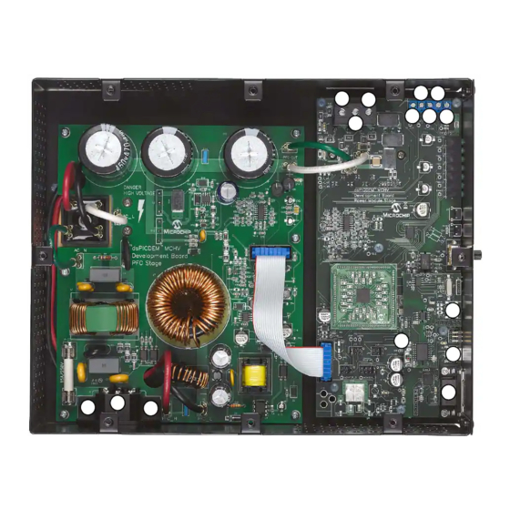
The second stage is the power module board. This board contains the dsPIC DSC connector, the isolated user interface connectors, and the motor drive. Figure 2-1 shows an interior view of the system. FIGURE 2-1: dsPICDEM™ MCHV DEVELOPMENT SYSTEM 2009 Microchip Technology Inc. DS70605A-page 13 Arrow.com. Arrow.com. Arrow.com. -
Page 20: User Interface
• Power Supply Connector (Figure 2-4) - AC power inlet specified for 40VAC-220VAC 10Amps max (J1) FIGURE 2-2: dsPICDEM™ MCHV DEVELOPMENT SYSTEM (FRONT) POT1 PWM LED Reset Indicators J2,J3 2009 Microchip Technology Inc. DS70605A-page 14 Arrow.com. Arrow.com. Arrow.com. Arrow.com. Arrow.com. Arrow.com. Arrow.com. -
Page 21: Connecting The System
If possible, all wires should be stripped and tinned with solder before connecting to the dsPICDEM™ MCHV Development System terminals. 2009 Microchip Technology Inc. DS70605A-page 15 Arrow.com. - Page 22 Figure 2-6 provides the locations of all connectors. Corresponding tables that describe each connection are provided in the relevant section. FIGURE 2-5: dsPICDEM™ MCHV DEVELOPMENT SYSTEM CONNECTIONS The power connections are listed in Table 2-1. 2009 Microchip Technology Inc. DS70605A-page 16 Arrow.com. Arrow.com. Arrow.com.
- Page 23 If the motor position is sensed with a Quadrature Encoder, connect the ter- minals phase A, phase B, and Index to the connection nodes HA, HB, and HC (7, 8, and 9 in Figure 2-5), respectively. 2009 Microchip Technology Inc. DS70605A-page 17 Arrow.com.
- Page 24 As the unit has no mains switch, this plug constitutes the means of disconnection from the supply. Therefore, the user must have unobstructed access to this plug during operation. 2009 Microchip Technology Inc. DS70605A-page 18 Arrow.com. Arrow.com.
-
Page 25: Power Sequences
IDE documentation mentioned at the beginning of this chapter. 2. Select Project>Build All to build the application code. The build’s progress will be visible in the Build tab of the Output window. 2009 Microchip Technology Inc. DS70605A-page 19 Arrow.com. - Page 26 Starter Kit debug functions and (4) the Output window will dis- play communication status between MPLAB IDE and the stater kit on the Starter Kit Debugger tab. FIGURE 2-6: STARTER KIT AS A DEBUG TOOL 2009 Microchip Technology Inc. DS70605A-page 20 Arrow.com. Arrow.com. Arrow.com.
- Page 27 Repeatedly click the button to step through the code. 5. Select Debugger>Reset>Processor Reset click the Reset button to reset the program again. The arrow will disappear, meaning the device is reset. 2009 Microchip Technology Inc. DS70605A-page 21 Arrow.com.
- Page 28 Project window in Figure 2-7. FIGURE 2-7: PROJECT EXAMPLE Existing Code For more information on using the MPLAB Editor to create and edit code, see the MPLAB Editor Help. 2009 Microchip Technology Inc. DS70605A-page 22 Arrow.com. Arrow.com. Arrow.com. Arrow.com.
- Page 29 See the MPLAB IDE Help for more information on this dialog. A breakpoint set in code will appear as a red hexagon with a “B” as shown in Figure 2-8. FIGURE 2-8: BREAKPOINT EXAMPLE 2009 Microchip Technology Inc. DS70605A-page 23 Arrow.com. Arrow.com. Arrow.com.
- Page 30 1. Disable Starter Kits as a debug tool by selecting Debugger>Select Tool>None. 2. Select Starter Kits as the programmer in the Programmer>Select Programmer menu. 3. Select Programmer>Program. At this point, the application code will run independently. 2009 Microchip Technology Inc. DS70605A-page 24 Arrow.com. Arrow.com. Arrow.com.
- Page 31 • Firmware Version: The version of firmware on the Starter Kit board. • Debug Exec Version: The version of the debug executive that is loaded into the dsPIC33F device program memory to enable debug operation. 2009 Microchip Technology Inc. DS70605A-page 25 Arrow.com.
- Page 32 MCHV Development System User’s Guide NOTES: 2009 Microchip Technology Inc. DS70605A-page 26 Arrow.com. Arrow.com. Arrow.com. Arrow.com. Arrow.com. Arrow.com. Arrow.com. Arrow.com. Arrow.com. Arrow.com. Arrow.com. Arrow.com. Arrow.com. Arrow.com. Arrow.com. Arrow.com. Arrow.com. Arrow.com. Arrow.com. Arrow.com. Arrow.com. Arrow.com. Arrow.com. Arrow.com. Arrow.com. Arrow.com.
-
Page 33: Chapter 3. Running The Demonstration
Make sure the PWM OUTPUT shunt jumper is installed. b) To start/stop the motor, press the switch labeled “PUSHBUTTON”. c) To increase the motor speed, rotate the potentiometer labeled “POT” clockwise. To reduce the speed, rotate the potentiometer counterclockwise. 2009 Microchip Technology Inc. DS70605A-page 27 Arrow.com. Arrow.com. - Page 34 MCHV Development System User’s Guide NOTES: 2009 Microchip Technology Inc. DS70605A-page 28 Arrow.com. Arrow.com. Arrow.com. Arrow.com. Arrow.com. Arrow.com. Arrow.com. Arrow.com. Arrow.com. Arrow.com. Arrow.com. Arrow.com. Arrow.com. Arrow.com. Arrow.com. Arrow.com. Arrow.com. Arrow.com. Arrow.com. Arrow.com. Arrow.com. Arrow.com. Arrow.com. Arrow.com. Arrow.com. Arrow.com.
-
Page 35: Chapter 4. Hardware
• BR1 – A single-phase bridge rectifier to convert the incoming AC into DC suitable for input to the power conditioning stage. 2009 Microchip Technology Inc. DS70605A-page 29 Arrow.com. Arrow.com. - Page 36 • The power factor corrector design is based on the application note AN1106, for more information on this application note please refer to one of the following Microchip Web sites: - www.microchip.com/smps - www.microchip.com/dscmotor 2009 Microchip Technology Inc. DS70605A-page 30 Arrow.com. Arrow.com. Arrow.com.
- Page 37 The PFC stage board also provides the 3.3 volts to powering-up the dsPIC DSC, the isolation circuitry, the communication ports, the Starter Kit programmer, etc. It also gen- erates the 3.3 volts for powering the analog circuits and the analog reference for the Analog-To-Digital converter. 2009 Microchip Technology Inc. DS70605A-page 31 Arrow.com. Arrow.com.
- Page 38 If possible, all wires should be stripped and tinned with solder before connecting to the dsPICDEM MCHV development board terminals. 2009 Microchip Technology Inc.
-
Page 39: Power Module Stage
If possible, all wires should be stripped and tinned with solder before connecting to the dsPICDEM MCHV development board terminals. Note: The user should only access the power terminals when the system is fully discharged (see the “Safety Notice”... - Page 40 R32, Remove R7 and R8 — USB_RX — Not connected Not applicable — USB_TX — Not connected Not applicable ASDA1/RP5/CN27/RB5 R6, Remove R5 and R33 2009 Microchip Technology Inc. DS70605A-page 34 Arrow.com. Arrow.com. Arrow.com. Arrow.com. Arrow.com. Arrow.com. Arrow.com. Arrow.com. Arrow.com. Arrow.com. Arrow.com.
- Page 41 R3, Remove R26 SOSCI/RP4/CN1/RB4 — USB_RX — Not connected Not applicable — USB_TX — Not connected Not applicable RP24/CN20/RC8 R2, Remove R18 2009 Microchip Technology Inc. DS70605A-page 35 Arrow.com. Arrow.com. Arrow.com. Arrow.com. Arrow.com. Arrow.com. Arrow.com. Arrow.com. Arrow.com. Arrow.com. Arrow.com. Arrow.com.
- Page 42 U2TX/CN18/RF5 Not applicable — USB_RX — Not connected Not applicable — USB_TX — Not connected Not applicable IC1/RD8 Not applicable 2009 Microchip Technology Inc. DS70605A-page 36 Arrow.com. Arrow.com. Arrow.com. Arrow.com. Arrow.com. Arrow.com. Arrow.com. Arrow.com. Arrow.com. Arrow.com. Arrow.com. Arrow.com. Arrow.com.
- Page 43 3.3V rail. R53 and C40 form a low-pass RC filter that filters out the frequencies above 53 kHz. For more information about this power module please refer to the manufacturer’s data sheet. 2009 Microchip Technology Inc. DS70605A-page 37 Arrow.com. Arrow.com.
- Page 44 U13D. R54 and C42 filter out the high-frequency noise. Note: It is possible to select any of these feedback signals using jumpers J12, J13 and J14, please refer to Section 4.2.8 “User Interfaces” for more information. 2009 Microchip Technology Inc. DS70605A-page 38 Arrow.com. Arrow.com. Arrow.com.
- Page 45 Designator Position Description Connects UART receive line to RX. Connects USB receive line to RX. Connects UART transmit line to TX. Connects USB transmit line to TX. 2009 Microchip Technology Inc. DS70605A-page 39 Arrow.com. Arrow.com. Arrow.com. Arrow.com. Arrow.com. Arrow.com.
- Page 46 Connects Hall B/QEB sensor signal to MONITOR_2 Connects DC bus shunt current feedback to MONITOR_3 Connects Phase M3 voltage feedback to MONITOR_3 Connects Hall C/INDEX sensor signal to MONITOR_3 Connects the POT voltage to MONITOR_3 2009 Microchip Technology Inc. DS70605A-page 40 Arrow.com. Arrow.com. Arrow.com.
- Page 47 4.2.10 Board Connectors Figure 4-1 provides the locations of the connectors. The Power Module Stage Board connectors are listed in Table 4-6. FIGURE 4-1: POWER MODULE BOARD CONNECTORS 2009 Microchip Technology Inc. DS70605A-page 41 Arrow.com. Arrow.com. Arrow.com. Arrow.com. Arrow.com.
- Page 48 VAC zero crossing signal Output Ground, digital rail Output PWM signal for the PFC IGBT Input Ground, digital rail Output Not Connected Output Not Connected 2009 Microchip Technology Inc. DS70605A-page 42 Arrow.com. Arrow.com. Arrow.com. Arrow.com. Arrow.com. Arrow.com. Arrow.com. Arrow.com. Arrow.com.
-
Page 49: Electrical Specifications
PFC IGBT. To provide additional air flow, a conventional AC muffin fan can be used (Comair-rotron part number 028021 or 028023). An alternative bonded fin heat sink with fans attached is also an option (C&H Technology, Inc. part number CH5117F). 2009 Microchip Technology Inc. DS70605A-page 43 Arrow.com. Arrow.com. - Page 50 MCHV Development System User’s Guide NOTES: 2009 Microchip Technology Inc. DS70605A-page 44 Arrow.com. Arrow.com. Arrow.com. Arrow.com. Arrow.com. Arrow.com. Arrow.com. Arrow.com. Arrow.com. Arrow.com. Arrow.com. Arrow.com. Arrow.com. Arrow.com. Arrow.com. Arrow.com. Arrow.com. Arrow.com. Arrow.com. Arrow.com. Arrow.com. Arrow.com. Arrow.com. Arrow.com. Arrow.com. Arrow.com.
-
Page 51: Appendix A. Board Layout And Schematics
MCHV DEVELOPMENT SYSTEM USER’S GUIDE Appendix A. Board Layout and Schematics FIGURE A-1: PFC STAGE BOARD LAYOUT (TOP) 2009 Microchip Technology Inc. DS70605A-page 45 Arrow.com. Arrow.com. Arrow.com. Arrow.com. Arrow.com. Arrow.com. Arrow.com. Arrow.com. Arrow.com. Arrow.com. Arrow.com. Arrow.com. Arrow.com. Arrow.com. - Page 52 MCHV Development System User’s Guide FIGURE A-2: PFC STAGE SCHEMATIC (SHEET 1 OF 3) 2009 Microchip Technology Inc. DS70605A-page 46 Arrow.com. Arrow.com. Arrow.com. Arrow.com. Arrow.com. Arrow.com. Arrow.com. Arrow.com. Arrow.com. Arrow.com. Arrow.com. Arrow.com. Arrow.com. Arrow.com. Arrow.com. Arrow.com. Arrow.com. Arrow.com.
- Page 53 Board Layout and Schematics FIGURE A-3: PFC STAGE SCHEMATIC (SHEET 2 OF 3) 2009 Microchip Technology Inc. DS70605A-page 47 Arrow.com. Arrow.com. Arrow.com. Arrow.com. Arrow.com. Arrow.com. Arrow.com. Arrow.com. Arrow.com. Arrow.com. Arrow.com. Arrow.com. Arrow.com. Arrow.com. Arrow.com. Arrow.com. Arrow.com. Arrow.com. Arrow.com. Arrow.com.
- Page 54 MCHV Development System User’s Guide FIGURE A-4: PFC STAGE SCHEMATIC (SHEET 3 OF 3) 2009 Microchip Technology Inc. DS70605A-page 48 Arrow.com. Arrow.com. Arrow.com. Arrow.com. Arrow.com. Arrow.com. Arrow.com. Arrow.com. Arrow.com. Arrow.com. Arrow.com. Arrow.com. Arrow.com. Arrow.com. Arrow.com. Arrow.com. Arrow.com. Arrow.com.
- Page 55 Board Layout and Schematics FIGURE A-5: POWER MODULE STAGE BOARD LAYOUT (TOP) 2009 Microchip Technology Inc. DS70605A-page 49 Arrow.com. Arrow.com. Arrow.com. Arrow.com. Arrow.com. Arrow.com. Arrow.com. Arrow.com. Arrow.com. Arrow.com. Arrow.com. Arrow.com. Arrow.com. Arrow.com. Arrow.com. Arrow.com. Arrow.com. Arrow.com. Arrow.com. Arrow.com. Arrow.com.
- Page 56 MCHV Development System User’s Guide FIGURE A-6: POWER MODULE STAGE BOARD LAYOUT (BOTTOM) 2009 Microchip Technology Inc. DS70605A-page 50 Arrow.com. Arrow.com. Arrow.com. Arrow.com. Arrow.com. Arrow.com. Arrow.com. Arrow.com. Arrow.com. Arrow.com. Arrow.com. Arrow.com. Arrow.com. Arrow.com. Arrow.com. Arrow.com. Arrow.com. Arrow.com. Arrow.com.
- Page 57 Board Layout and Schematics FIGURE A-7: POWER MODULE STAGE SCHEMATIC (SHEET 1 OF 6) 2009 Microchip Technology Inc. DS70605A-page 51 Arrow.com. Arrow.com. Arrow.com. Arrow.com. Arrow.com. Arrow.com. Arrow.com. Arrow.com. Arrow.com. Arrow.com. Arrow.com. Arrow.com. Arrow.com. Arrow.com. Arrow.com. Arrow.com. Arrow.com. Arrow.com. Arrow.com.
- Page 58 MCHV Development System User’s Guide FIGURE A-8: POWER MODULE STAGE SCHEMATIC (SHEET 2 OF 6) 2009 Microchip Technology Inc. DS70605A-page 52 Arrow.com. Arrow.com. Arrow.com. Arrow.com. Arrow.com. Arrow.com. Arrow.com. Arrow.com. Arrow.com. Arrow.com. Arrow.com. Arrow.com. Arrow.com. Arrow.com. Arrow.com. Arrow.com. Arrow.com.
- Page 59 Board Layout and Schematics FIGURE A-9: POWER MODULE STAGE SCHEMATIC (SHEET 3 OF 6) 2009 Microchip Technology Inc. DS70605A-page 53 Arrow.com. Arrow.com. Arrow.com. Arrow.com. Arrow.com. Arrow.com. Arrow.com. Arrow.com. Arrow.com. Arrow.com. Arrow.com. Arrow.com. Arrow.com. Arrow.com. Arrow.com. Arrow.com. Arrow.com. Arrow.com. Arrow.com.
- Page 60 MCHV Development System User’s Guide FIGURE A-10: POWER MODULE STAGE SCHEMATIC (SHEET 4 OF 6) 2009 Microchip Technology Inc. DS70605A-page 54 Arrow.com. Arrow.com. Arrow.com. Arrow.com. Arrow.com. Arrow.com. Arrow.com. Arrow.com. Arrow.com. Arrow.com. Arrow.com. Arrow.com. Arrow.com. Arrow.com. Arrow.com. Arrow.com. Arrow.com.
- Page 61 Board Layout and Schematics FIGURE A-11: POWER MODULE STAGE SCHEMATIC (SHEET 5 OF 6) 2009 Microchip Technology Inc. DS70605A-page 55 Arrow.com. Arrow.com. Arrow.com. Arrow.com. Arrow.com. Arrow.com. Arrow.com. Arrow.com. Arrow.com. Arrow.com. Arrow.com. Arrow.com. Arrow.com. Arrow.com. Arrow.com. Arrow.com. Arrow.com. Arrow.com. Arrow.com.
- Page 62 MCHV Development System User’s Guide FIGURE A-12: POWER MODULE STAGE SCHEMATIC (SHEET 6 OF 6) 2009 Microchip Technology Inc. DS70605A-page 56 Arrow.com. Arrow.com. Arrow.com. Arrow.com. Arrow.com. Arrow.com. Arrow.com. Arrow.com. Arrow.com. Arrow.com. Arrow.com. Arrow.com. Arrow.com. Arrow.com. Arrow.com. Arrow.com. Arrow.com.
- Page 63 Using Breakpoints and Mouseovers ......23 Using Watch Windows ..........24 Interface Components..........14 Internet Address............4 Inverter Leg Shunt Resistor Feedback..... 38 Warranty Registration ..........3 WWW Address............4 2009 Microchip Technology Inc. DS70605A-page 57 Arrow.com. Arrow.com. Arrow.com. Arrow.com. Arrow.com.
- Page 64 Fax: 86-29-8833-7256 Fax: 66-2-694-1350 Fax: 408-961-6445 China - Zhuhai Toronto Tel: 86-756-3210040 Mississauga, Ontario, Fax: 86-756-3210049 Canada Tel: 905-673-0699 Fax: 905-673-6509 03/26/09 2009 Microchip Technology Inc. DS70605A-page 58 Arrow.com. Arrow.com. Arrow.com. Arrow.com. Arrow.com. Arrow.com. Arrow.com. Arrow.com. Arrow.com. Arrow.com. Arrow.com.
Need help?
Do you have a question about the DSPICDEM MCHV and is the answer not in the manual?
Questions and answers