
Related Manuals for Microchip Technology DM182017-1


Summary of Contents for Microchip Technology DM182017-1
- Page 1 Wireless Security Remote Control Development Kit User’s Guide 2012 Microchip Technology Inc. DS41646A...
- Page 2 Select Mode, Total Endurance, TSHARC, UniWinDriver, WiperLock and ZENA are trademarks of Microchip Technology Incorporated in the U.S.A. and other countries. SQTP is a service mark of Microchip Technology Incorporated in the U.S.A. All other trademarks mentioned herein are property of their respective companies.
- Page 3 Object of Declaration: Wireless Security Remote Control Development Kit 2012 Microchip Technology Inc. DS41646A-page 3...
- Page 4 Wireless Security Remote Control Development Kit User’s Guide NOTES: 2012 Microchip Technology Inc. DS41646A-page 4...
-
Page 5: Table Of Contents
6.3 Developing with the Embedded Security Development Board as Receiver . 32 Appendix A. PIC12LF1840T39A Wireless Remote Key Fob Schematics Appendix B. SX1239 Receiver PICtail™ Daughter Board Schematics Appendix C. Embedded Security Development Board Schematics Worldwide Sales and Service ..................50 2012 Microchip Technology Inc. DS41646A-page 5... - Page 6 Wireless Security Remote Control Development Kit User’s Guide NOTES: 2012 Microchip Technology Inc. DS41646A-page 6...
-
Page 7: Preface
Chapter 4. “SX1239 Receiver PICtail™ Daughter Board” provides the hardware details of the Receiver PICtail Daughter Board. • – This chapter provides Chapter 5. “Embedded Security Development Board” the hardware details of the Embedded Security Development Board. 2012 Microchip Technology Inc. DS41646A-page 7... - Page 8 Curly brackets and pipe Choice of mutually exclusive errorlevel {0|1} character: { | } arguments; an OR selection Ellipses... Replaces repeated text var_name [, var_name...] Represents code supplied by void main (void) user { ... 2012 Microchip Technology Inc. DS41646A-page 8...
- Page 9 • AN1265 “K with AES Microcontroller-based Code Hopping Encoder” ® • AN743 “Modular PIC Mid-Range MCU Code Hopping Decoder” ® • AN745 “Modular Mid-Range PIC Decoder in C” ® • AN1275 “K with AES Receiver/Decoder” 2012 Microchip Technology Inc. DS41646A-page 9...
- Page 10 MPLAB REAL ICE in-circuit emulator, MPLAB ICD 3 in-circuit debugger and MPLAB PM3 device programmers. Also included ® are nonproduction development programmers such as PICSTART Plus and PICkit 2 and 3. 2012 Microchip Technology Inc. DS41646A-page 10...
- Page 11 Technical support is available through the web site at: http://www.microchip.com/support. REVISION HISTORY Revision A (July 2012) • Initial Release of this Document. 2012 Microchip Technology Inc. DS41646A-page 11...
- Page 12 Wireless Security Remote Control Development Kit User’s Guide NOTES: 2012 Microchip Technology Inc. DS41646A-page 12...
-
Page 13: Chapter 1. Overview
The Wireless Security Remote Control Development Kits have three frequency choices: • Wireless Security Remote Control Development Kit – 433.92 MHz (DM182017-1) • Wireless Security Remote Control Development Kit – 868 MHz (DM182017-2) • Wireless Security Remote Control Development Kit – 915 MHz (DM182017-3) Each kit contains: •... - Page 14 Wireless Security Remote Control Development Kit User’s Guide NOTES: 2012 Microchip Technology Inc. DS41646A-page 14...
-
Page 15: Chapter 2. Getting Started
4. Plug in the RF receiver daughter board on the PICtail slot of the Embedded Security Development Board. Make sure that the RF receiver daughter board has the side with RF receiver chip face the center, as shown in Figure 2-1. 2012 Microchip Technology Inc. DS41646A-page 15... -
Page 16: Demo Operation
AES Microcontroller-Based Code Hopping Encoder”. The key fob has four push buttons and is powered by a CR2032 coin battery. The key fob is shown in Figure 2-2, where the four buttons are labeled individually. 2012 Microchip Technology Inc. DS41646A-page 16... - Page 17 To learn a transmitter, the receiver initiates the learning process by pressing button SW4. The learning procedure will be started and the message “Learn mode active” will be displayed on the LCD, as shown in Figure 2-4. FIGURE 2-4: START LEARN MODE 2012 Microchip Technology Inc. DS41646A-page 17...
- Page 18 2-7) in this transmission • Function Code: A bitmap of the pressed buttons (it will be 3 if both KLQ buttons are pressed), depending on the button pressed on the key fob FIGURE 2-7: PACKET INFORMATION 2012 Microchip Technology Inc. DS41646A-page 18...
-
Page 19: Embedded Security Development Board Hardware Self-Check
The user should observe that all LEDs are turned on and off with flashing intervals of roughly one second. Once the user has verified the LED test, SW1 needs to be pressed to move forward to the RTCC test. 2012 Microchip Technology Inc. DS41646A-page 19... - Page 20 Daughter Board is plugged into the PICtail connector, even though the SPI bus may still work, the SPI test might show failure status. The reason is due to the expected values to be received from the SX1239. 2012 Microchip Technology Inc. DS41646A-page 20...
-
Page 21: Chapter 3. Pic12Lf1840T39A Wireless Remote Key Fob
The PCB antenna is explained in more detail below. P1 is the ICSP™ programming port. See Chapter 6. “Developing with the Wireless for suggestions on developing and Security Remote Control Development Kit” programming the key fob. 2012 Microchip Technology Inc. DS41646A-page 21... -
Page 22: Pcb Antenna Description
This type of antenna has an extremely high quality factor (Q). Therefore, it is very susceptible to parasitic impedances and very challenging to impedance match to the transmitter. 2012 Microchip Technology Inc. DS41646A-page 22... - Page 23 FIGURE 3-4: PCB ANTENNA DIMENSIONS Figure 3-5 shows the simulated three-dimensional plot of the radiation patter from the antenna. Figure 3-6 shows the two-dimensional plots. FIGURE 3-5: PCB ANTENNA 3D RADIATION PATTERN (SIMULATED) 2012 Microchip Technology Inc. DS41646A-page 23...
- Page 24 Wireless Security Remote Control Development Kit User’s Guide FIGURE 3-6: PCB ANTENNA 2D RADIATION PATTERN (SIMULATED) 2012 Microchip Technology Inc. DS41646A-page 24...
-
Page 25: Chapter 4. Sx1239 Receiver Pictail™ Daughter Board
The antenna connection has a pin socket for plugging a wire antenna. This demonstrates a simple and low-cost antenna option. The length of the antenna should be approximately ¼ wavelength of the frequency of interest. 2012 Microchip Technology Inc. DS41646A-page 25... - Page 26 The antenna pin socket can be removed by heating it with a soldering iron and cleaning the connection. An SMA or reverse polarity SMA (RP-SMA) connector can be soldered in place on the PCB. A whip or sleeve dipole antenna can then be used. 2012 Microchip Technology Inc. DS41646A-page 26...
-
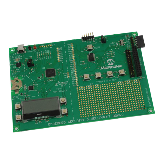
Page 27: Chapter 5. Embedded Security Development Board
5. PICtail™ Connector J1 6. 16x2 character LCD display 7. Real-Time Clock and Calendar (RTCC) module U5 8. Push Buttons 9. LEDs 10. Voltage Regulator 11. ICSP™ Programming Ports, J4 for Host; J5 for Target Application 2012 Microchip Technology Inc. DS41646A-page 27... -
Page 28: Hardware Description
UART and full-speed USB 2.0 communication. At the same time, the USB interface port can be used to power the Embedded Security Development Board directly. For more information, please refer to the Microchip MCP2200 data sheet. 2012 Microchip Technology Inc. DS41646A-page 28... - Page 29 All buttons are assigned to the individual interrupt lines of the microcontroller and are not driven by external pull-up circuitry to save power consumption. The user software must enable the PORTB pull-ups of the microcontroller before evaluating the button state. 2012 Microchip Technology Inc. DS41646A-page 29...
- Page 30 The ICSP port J5 on the right is used to program the target application microcontroller. Figure 5-2 shows the ICSP ports. FIGURE 5-2: ICSP™ PROGRAMMING/DEBUGGING PORTS Master Slave ™ ICSP port ™ ICSP port 2012 Microchip Technology Inc. DS41646A-page 30...
-
Page 31: Chapter 6. Developing With The Wireless Security Remote Control Development Kit
As a secured RKE system, K security keys, especially the manufacturer key is essential to the security of the whole system. It is highly recommended to use ® code-protect of the PIC MCU memory. 2012 Microchip Technology Inc. DS41646A-page 31... -
Page 32: Developing With The Embedded Security Development Board As Receiver
SPI slave, and thus requires faster response to the SPI command. Generally speaking, if no SPI delay is applied by the target application controller side, the operation speed of the host microcontroller needs to be double that of the target application microcontroller. 2012 Microchip Technology Inc. DS41646A-page 32... -
Page 33: Appendix A. Pic12Lf1840T39A Wireless Remote Key Fob Schematics
WIRELESS SECURITY REMOTE CONTROL DEVELOPMENT KIT USER’S GUIDE Appendix A. PIC12LF1840T39A Wireless Remote Key Fob Schematics FIGURE A-1: KEY FOB PCB ASSEMBLY – TOP SILKSCREEN FIGURE A-2: KEY FOB PCB ASSEMBLY – TOP COPPER 2012 Microchip Technology Inc. DS41646A-page 33... - Page 34 Wireless Security Remote Control Development Kit User’s Guide FIGURE A-3: KEY FOB PCB ASSEMBLY – BOTTOM COPPER FIGURE A-4: KEY FOB PCB ASSEMBLY – BOTTOM SILKSCREEN 2012 Microchip Technology Inc. DS41646A-page 34...
-
Page 35: Microchip Technology Inc. Ds41646A
PIC12LF1840T39A Wireless Remote Key Fob Schematics FIGURE A-5: KEY FOB SCHEMATIC ICSP™ 2012 Microchip Technology Inc. DS41646A-page 35... - Page 36 ±5%, SMT 0402 North America Do not populate — — Do not populate — — 0 Ω Resistor, 5%, ±100 Yageo RC0402JR-070RL ppm/C, SMT 0402 24 MHz CRYSTAL 24.000 MHz Abracon Corporation ABM8G-24.000MHZ-18-D2 2012 Microchip Technology Inc. DS41646A-page 36...
- Page 37 North America 1.8 nH Inductor, Ceramic, ±5%, Murata Electronics LQP15MN1N8B02D SMT 0402 North America 15 nH Inductor, Ceramic, ±5%, Murata Electronics LQP15MN15NG02D SMT 0402 North America 26 MHz CRYSTAL 26.000 MHz Abracon Corporation ABM8G-26.000MHZ-18-D2 2012 Microchip Technology Inc. DS41646A-page 37...
- Page 38 Wireless Security Remote Control Development Kit User’s Guide NOTES: 2012 Microchip Technology Inc. DS41646A-page 38...
-
Page 39: Appendix B. Sx1239 Receiver Pictail™ Daughter Board Schematics
WIRELESS SECURITY REMOTE CONTROL DEVELOPMENT KIT USER’S GUIDE Appendix B. SX1239 Receiver PICtail™ Daughter Board Schematics FIGURE B-1: SX1239 RECEIVER PICtail™ PCB ASSEMBLY 2012 Microchip Technology Inc. DS41646A-page 39... - Page 40 Wireless Security Remote Control Development Kit User’s Guide FIGURE B-2: RECEIVER PICtail™ SCHEMATIC 2012 Microchip Technology Inc. DS41646A-page 40...
- Page 41 13 nH Inductor, 13nH, 500mA, Air TDK Corporation MLG1005S13NJ Core, 5% 3.6 pF Cap, Ceramic, 3.6pF, 50V Murata Electronics GRM1555C1H3R6CZ01D +/-5% COG North America Designator A1 Wire Antenna: Cut to 6.75 in. OAL. Note: 2012 Microchip Technology Inc. DS41646A-page 41...
- Page 42 Wireless Security Remote Control Development Kit User’s Guide NOTES: 2012 Microchip Technology Inc. DS41646A-page 42...
-
Page 43: Appendix C. Embedded Security Development Board Schematics
WIRELESS SECURITY REMOTE CONTROL DEVELOPMENT KIT USER’S GUIDE Appendix C. Embedded Security Development Board Schematics FIGURE C-1: EMBEDDED SECURITY DEVELOPMENT BOARD PCB ASSEMBLY 2012 Microchip Technology Inc. DS41646A-page 43... - Page 44 Wireless Security Remote Control Development Kit User’s Guide FIGURE C-2: EMBEDDED SECURITY DEVELOPMENT BOARD SCHEMATIC (1 OF 2) 2012 Microchip Technology Inc. DS41646A-page 44...
- Page 45 Embedded Security Development Board Schematics FIGURE C-3: EMBEDDED SECURITY DEVELOPMENT BOARD SCHEMATIC (2 OF 2) 2012 Microchip Technology Inc. DS41646A-page 45...
- Page 46 Murata GRM188R61A105MA61D 1 µf Murata GRM188R61A105MA61D 1 µf Murata GRM188R61A105MA61D B0520WS Diodes Inc. B0520WS-7-F Fairchild Semiconductor BAT54 Lite-On LTST-C191GKT Lite-On LTST-C191GKT Lite-On LTST-C191GKT Lite-On LTST-C191GKT Lite-On LTST-C191GKT Lite-On LTST-C191GKT Lite-On LTST-C191GKT Lite-On LTST-C191GKT 2012 Microchip Technology Inc. DS41646A-page 46...
- Page 47 Stackpole Electronics International RMCF0603FT330R 330 Ω Stackpole Electronics International RMCF0603FT330R 330 Ω Stackpole Electronics International RMCF0603FT330R 330 Ω Stackpole Electronics International RMCF0603FT330R 330 Ω Stackpole Electronics International RMCF0603FT330R 1k Ω Stackpole Electronics International RMCF0603FT1K00 2012 Microchip Technology Inc. DS41646A-page 47...
- Page 48 Microchip Technology Inc. PIC16LF1947-I/PT MCP2200 Microchip Technology Inc. MCP2200-I/MQ MCP1703-3.3 Microchip Technology Inc. MCP1703T-3302E/MB PIC16LF1938-I/SS_28-PIN Microchip Technology Inc. PIC16LF1938-I/SS MCP795W10-I/ST Microchip Technology Inc. MCP795W10-I/ST 12 MHz NX3225SA-12.000000MHZ 32.768 kHz Abracon ABS06-32.768KHZ-T 32.768 kHz Abracon ABS06-32.768KHZ-T 2012 Microchip Technology Inc. DS41646A-page 48...
- Page 49 Wireless Security Remote Control Development Kit User’s Guide NOTES: 2012 Microchip Technology Inc. DS41646A-page 49...
-
Page 50: Worldwide Sales And Service
Thailand - Bangkok Tel: 86-29-8833-7252 Tel: 66-2-694-1351 Toronto Fax: 86-29-8833-7256 Fax: 66-2-694-1350 Mississauga, Ontario, Canada China - Xiamen Tel: 905-673-0699 Tel: 86-592-2388138 Fax: 905-673-6509 Fax: 86-592-2388130 China - Zhuhai Tel: 86-756-3210040 11/29/11 Fax: 86-756-3210049 2012 Microchip Technology Inc. DS41646A-page 50... - Page 51 Mouser Electronics Authorized Distributor Click to View Pricing, Inventory, Delivery & Lifecycle Information: Microchip DM182017-1 DM182017-2 DM182017-3...
Need help?
Do you have a question about the DM182017-1 and is the answer not in the manual?
Questions and answers