Table of Contents
Advertisement
Quick Links
Advertisement
Table of Contents

Related Manuals for Microchip Technology DM164120-1


Summary of Contents for Microchip Technology DM164120-1
- Page 1 Low Pin Count Demo Board User’s Guide © 2005 Microchip Technology Inc. DS51556A...
- Page 2 Smart Serial, SmartTel, Total Endurance and WiperLock are trademarks of Microchip Technology Incorporated in the U.S.A. and other countries. SQTP is a service mark of Microchip Technology Incorporated in the U.S.A. All other trademarks mentioned herein are property of their respective companies.
-
Page 3: Table Of Contents
Lesson 10: Interrupts .................... 29 3.2.11 Lesson 11: Indirect Data Addressing ..............31 3.2.12 Lesson 12: Look-up Table (ROM Array) ............... 33 Appendix A. Hardware Schematics A.1 Introduction ....................37 Worldwide Sales and Service ..................38 © 2005 Microchip Technology Inc. DS51556A-page iii... - Page 4 Low Pin Count Demo Board User’s Guide NOTES: © 2005 Microchip Technology Inc. DS51556A-page iv...
-
Page 5: Preface
Architectural Overview” – An overview of ® the Mid-range PICmicro Architecture. • Chapter 3. “LPC Demo Board Lessons” – Contains a variety of lessons that demonstrate how to utilize and experiment with the Low Pin Count Demo Board. © 2005 Microchip Technology Inc. DS51556A-page 1... - Page 6 Curly brackets and pipe Choice of mutually exclusive errorlevel {0|1} character: { | } arguments; an OR selection Ellipses... Replaces repeated text var_name [, var_name...] Represents code supplied by void main (void) user { ... © 2005 Microchip Technology Inc. DS51556A-page 2...
- Page 7 Flash based, 8-bit CMOS Microcontroller device specifications. ® MPLAB IDE, Simulator, Editor User’s Guide (DS51025) Consult this document for more information pertaining to the installation and features of the MPLAB Integrated Development Environment (IDE) Software. © 2005 Microchip Technology Inc. DS51556A-page 3...
- Page 8 • Programmers – The latest information on Microchip programmers. These include ® ® the MPLAB PM3 and PRO MATE II device programmers and the PICSTART ® Plus and PICkit 1 development programmers. © 2005 Microchip Technology Inc. DS51556A-page 4...
- Page 9 The Development Systems Information Line numbers are: 1-800-755-2345 – United States and most of Canada 1-480-792-7302 – Other International Locations DOCUMENT REVISION HISTORY Revision A (May 2005) • Initial Release of this Document. © 2005 Microchip Technology Inc. DS51556A-page 5...
- Page 10 Low Pin Count Demo Board User’s Guide NOTES: © 2005 Microchip Technology Inc. DS51556A-page 6...
-
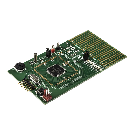
Page 11: Chapter 1. Low Pin Count (Lpc) Demo Board Overview
Starter Kit CD-ROM. 8-pin DIP Flash Devices: PIC12F508 PIC12F629 PIC12F635 PIC12F509 PIC12F675 PIC12F683 PIC12F510 14-pin DIP Flash Devices: PIC16F505 PIC16F630 PIC16F684 PIC16F506 PIC16F676 PIC16F688 20-pin DIP Flash Devices: PIC16F685 PIC16F689 PIC16F785 PIC16F687 PIC16F690 © 2005 Microchip Technology Inc. DS51556A-page 7... -
Page 12: Lpc Demo Board Overview
Push Button Switch, labeled SW1, and the sequence of the lights will reverse. Rotate the potentiometer, labeled RP1, and the light sequence will blink at a different rate. This demo program is developed through the first 7 lessons in this guide. © 2005 Microchip Technology Inc. DS51556A-page 8... -
Page 13: Chapter 2. Mid-Range Picmicro
256 bytes Memory File Registers Program RAM Addr Addr MUX Instruction Reg Indirect Direct Addr Addr FSR Reg Status Reg Instruction Decode and Control OSC1/CLKI Timing OSC2/CLKO W Reg Generation Internal Oscillator Block © 2005 Microchip Technology Inc. DS51556A-page 9... -
Page 14: Memory Organization
Literal instructions contain the data operand within the instruction. The Wreg becomes the other operand. Calls and GOTO’s use 11 bits as a literal address. MOVLW'A' Moves the ASCII value of ‘A’ (0x41) into Wreg. © 2005 Microchip Technology Inc. DS51556A-page 10... -
Page 15: Assembler Basics
The advantage is that as variables come and go through the development process, the cblock keeps the block to a minimum. Using one of the other methods, you may have to go back and find an unused location. © 2005 Microchip Technology Inc. DS51556A-page 11... - Page 16 Low Pin Count Demo Board User’s Guide NOTES: © 2005 Microchip Technology Inc. DS51556A-page 12...
-
Page 17: Chapter 3. Lpc Demo Board Lessons
• Lesson 7: Reversible Variable Speed Rotate • Lesson 8: Function Calls • Lesson 9: Timer0 • Lesson 10: Interrupts • Lesson 11: Indirect Data Addressing • Lesson 12: Look-up Table (ROM Array) © 2005 Microchip Technology Inc. DS51556A-page 13... -
Page 18: Lesson 1: Hello World (Light A Led)
I/O pin to a high condition turning on the LED. Tells the processor to go to the current instruction. GOTO $ For more information, refer to the I/O Ports Section of the PIC16F685/687/689/690 Data Sheet (DS41262). © 2005 Microchip Technology Inc. DS51556A-page 14... -
Page 19: Lesson 2: Delay Loop (Blink A Led)
Counting cycles – Relating clock speed to instruction speed. The processor requires 4 clocks to execute an instruction. Since the internal oscillator as used in these lessons runs at 4 MHz, the instruction rate is 1 MHz. © 2005 Microchip Technology Inc. DS51556A-page 15... - Page 20 Open Blink.asm and build the lesson. Next, import the hex file into the PICkit 2 and program the device. Note the LED now flashes at about a 2 Hz rate. © 2005 Microchip Technology Inc. DS51556A-page 16...
-
Page 21: Lesson 3: Rotate (Move The Led)
• Copy the Display variable to the I/O Port, then • Delay for a little while • Rotate the display FIGURE 3-1: ROTATE PROGRAM FLOW Initialize I/O Port Put Up Display Delay Rotate Display Did it overflow? Reset Display © 2005 Microchip Technology Inc. DS51556A-page 17... - Page 22 DECFSZ Delay2,f GOTO OndelayLoop STATUS,C ;ensure the carry bit is clear Display,f ;Rotate Display right BTFSC STATUS,C ;Did the bit rotate into the carry? Display,3 ;yes, put it into bit 3. GOTO MainLoop © 2005 Microchip Technology Inc. DS51556A-page 18...
-
Page 23: Lesson 4: Analog-To-Digital
Here’s the checklist for this lesson: • Configure PORTA as an analog input, TRISA<0> = 1, ANSEL<0> = 1 • Select clock scaling in ADCON1. • Select channel, justification and V source in ADCON0. © 2005 Microchip Technology Inc. DS51556A-page 19... - Page 24 R = Readable bit W = Writable bit U = Unimplemented bit, read as ‘0’ - n = Value at POR ‘1’ = Bit is set ‘0’ = Bit is cleared x = Bit is unknown © 2005 Microchip Technology Inc. DS51556A-page 20...
- Page 25 R = Readable bit W = Writable bit U = Unimplemented bit, read as ‘0’ - n = Value at POR ‘1’ = Bit is set ‘0’ = Bit is cleared x = Bit is unknown © 2005 Microchip Technology Inc. DS51556A-page 21...
-
Page 26: Lesson 5: Variable Speed Rotate
A2DDelayLoop DECFSZ Delay2,f GOTO A2DDelayLoop FIGURE 3-3: VARIABLE SPEED ROTATE PROGRAM FLOW Initialize I/O Port Initialize ADC Put Up Display Get ADC Result Delay Using ADC Rotate Display Did it overflow? Reset Display © 2005 Microchip Technology Inc. DS51556A-page 22... -
Page 27: Lesson 6: Switch Debouncing
Why suffer the additional expense when software is free and program memory is abundant. FIGURE 3-4: FILTERING DEBOUNCE SOLUTION Filtered Switch Output FIGURE 3-5: SHIFT REGISTER DEBOUNCE SOLUTION Filtered Switch Output Debounce Clock © 2005 Microchip Technology Inc. DS51556A-page 23... - Page 28 The Switch on the LPC Demo Board doesn’t bounce much, but it is good practice to debounce all switches in the system. FIGURE 3-6: SIMPLE SWITCH DEBOUNCE PROGRAM FLOW Switch has changed states? Increment Counter Reset Counter Is Counter = 5? Change State Reset Counter Delay 1 mS © 2005 Microchip Technology Inc. DS51556A-page 24...
-
Page 29: Lesson 7: Reversible Variable Speed Rotate
;Did the bit rotate into the carry? Display,3 ;yes, put it into bit 3. GOTO MainLoop RotateLeft Display,f BTFSC Display,4 ;did it rotate out of the display Display,0 ;yes, put it into bit 0 GOTO MainLoop © 2005 Microchip Technology Inc. DS51556A-page 25... -
Page 30: Lesson 8: Function Calls
;call delay function ;returns here when done GOTO ; Delay function. ; Delay time is Wreg value * 771 uS Delay MOVWF Delay2 DelayLoop DECFSZ Delay1,f GOTO DelayLoop DECFSZ Delay2,f GOTO DelayLoop RETURN © 2005 Microchip Technology Inc. DS51556A-page 26... -
Page 31: Lesson 9: Timer0
Thus, Timer0 Flag will be set every 65536 μs (0.0000001 second * 256 * 256), or about 15 times a second. The main program sits in a loop waiting for the rollover and when it does, it increments the display and then loops back. © 2005 Microchip Technology Inc. DS51556A-page 27... - Page 32 ForeverLoop BTFSS INTCON,T0IF ;wait here until Timer0 rolls over GOTO ForeverLoop INTCON,T0IF ;flag must be cleared in software INCF Display,f ;increment display variable MOVF Display,w ;send to the LEDs MOVWF PORTC GOTO ForeverLoop © 2005 Microchip Technology Inc. DS51556A-page 28...
-
Page 33: Lesson 10: Interrupts
Next, the ISR has to figure out what triggered the interrupt. It has to check the interrupt flags to determine what caused the interrupt. When it finds the source, then it can service the peripheral. © 2005 Microchip Technology Inc. DS51556A-page 29... - Page 34 Finally, RETFIE transfers control back to the original program and sets the GIE bit, re-enabling interrupts. FIGURE 3-10: SWAPF INSTRUCTION 1 0 1 0 0 0 1 1 Before After 0 0 1 1 1 0 1 0 © 2005 Microchip Technology Inc. DS51556A-page 30...
-
Page 35: Lesson 11: Indirect Data Addressing
;insert new value into a queue, enter with new value in ;Wreg MOVF temp ;save the latest value MOVF QueuePointer,w MOVWF FSR ;load FSR with the queue pointer MOVF temp,w MOVWF INDF ;Write the latest value to the queue © 2005 Microchip Technology Inc. DS51556A-page 31... - Page 36 Rather than summing the array every time, it’s faster to keep a running sum, then subtract out the oldest value in the queue and adding in the new value. © 2005 Microchip Technology Inc. DS51556A-page 32...
-
Page 37: Lesson 12: Look-Up Table (Rom Array)
PCLATH Section in the PIC16F685/687/689/690 Data Sheet (DS41262) for more details of how PCLATH is used. FIGURE 3-12: PC LOADING AS DESTINATION OF INSTRUCTION Instruction with PCL as Destination PCLATH<4:0> ALU Result PCLATH © 2005 Microchip Technology Inc. DS51556A-page 33... - Page 38 LEDs. The code changes one bit at a time as the potentiometer rotates across its range (see Example 3-12). Gray Code Converter Decimal Binary 0000 0001 0011 0010 0110 0111 0101 0100 1100 1101 1111 1110 1010 1011 1001 1000 © 2005 Microchip Technology Inc. DS51556A-page 34...
- Page 39 TableStart RETLW b'0000' RETLW b'0001' RETLW b'0011' RETLW b'0010' RETLW b'0110' RETLW b'0111' RETLW b'0101' RETLW b'0100' RETLW b'1100' RETLW b'1101' RETLW b'1111' RETLW b'1110' RETLW b'1010' RETLW b'1011' RETLW b'1001' RETLW b'1000' © 2005 Microchip Technology Inc. DS51556A-page 35...
- Page 40 Low Pin Count Demo Board User’s Guide NOTES: © 2005 Microchip Technology Inc. DS51556A-page 36...
-
Page 41: Appendix A. Hardware Schematics
PICKIT 2 USER’S GUIDE Appendix A. Hardware Schematics INTRODUCTION This appendix contains the Low Pin Count Demo Board Diagrams. FIGURE A-1: LOW PIN COUNT DEMO BOARD SCHEMATIC DIAGRAM © 2005 Microchip Technology Inc. DS51556A-page 37... -
Page 42: Worldwide Sales And Service
Tel: 765-864-8360 Fax: 886-3-572-6459 Fax: 765-864-8387 Los Angeles Mission Viejo, CA Tel: 949-462-9523 Fax: 949-462-9608 San Jose Mountain View, CA Tel: 650-215-1444 Fax: 650-961-0286 Toronto Mississauga, Ontario, Canada Tel: 905-673-0699 Fax: 905-673-6509 04/20/05 © 2005 Microchip Technology Inc. DS51556A-page 38...
Need help?
Do you have a question about the DM164120-1 and is the answer not in the manual?
Questions and answers