
Subscribe to Our Youtube Channel
Related Manuals for Microchip Technology DM182017-4


Summary of Contents for Microchip Technology DM182017-4
- Page 1 ® MCS3142 Dual K Encoder Wireless Remote Control Development Kit User’s Guide 2014 Microchip Technology Inc. DS40001746A...
- Page 2 Total Endurance, TSHARC, UniWinDriver, WiperLock, ZENA and Z-Scale are trademarks of Microchip Technology Incorporated in the U.S.A. and other countries. SQTP is a service mark of Microchip Technology Incorporated in the U.S.A. GestIC and ULPP are registered trademarks of Microchip Technology Germany II GmbH &...
- Page 3 ® Object of Declaration: MCS3142 Dual K Encoder Wireless Remote Control Development Kit 2014 Microchip Technology Inc. DS40001746A-page 3...
-
Page 4: Table Of Contents
5.4 USB Interface Port ..................23 5.5 PICtail™ Port ....................23 5.6 LCD Display ....................23 5.7 Real-Time Clock and Calendar (RTCC) Module .......... 23 5.8 Push Buttons ....................24 5.9 LEDs ......................24 2014 Microchip Technology Inc. DS40001746A-page 3... - Page 5 8.7 Receiver Settings ..................43 8.8 Versioning ....................43 Appendix A. MCS3142 Transmitter Fob Schematic Appendix B. SX1239 Receiver PICtail™ Daughter Board Schematics Appendix C. Embedded Security Development Board Schematics Worldwide Sales and Service ..................56 2014 Microchip Technology Inc. DS40001746A-page 4...
-
Page 6: Preface
• Chapter 7. “K MPLAB X Plugin” • Chapter 8. “PC Application” • Appendix A. “MCS3142 Transmitter Fob Schematic” • Appendix B. “SX1239 Receiver PICtail™ Daughter Board Schematics” • Appendix C. “Embedded Security Development Board Schematics” 2014 Microchip Technology Inc. DS40001746A-page 5... -
Page 7: Conventions Used In This Guide
Curly brackets and pipe Choice of mutually exclusive errorlevel {0|1} character: { | } arguments; an OR selection Ellipses... Replaces repeated text var_name [, var_name...] Represents code supplied by void main (void) user { ... 2014 Microchip Technology Inc. DS40001746A-page 6... -
Page 8: Recommended Reading
Microchip consultant program member listing • Business of Microchip – Product selector and ordering guides, latest Microchip press releases, listing of seminars and events, listings of Microchip sales offices, distributors and factory representatives 2014 Microchip Technology Inc. DS40001746A-page 7... -
Page 9: Customer Support
Technical support is available through the web site at: http://support.microchip.com DOCUMENT REVISION HISTORY Revision A (February 2014) • Initial Release of this Document. 2014 Microchip Technology Inc. DS40001746A-page 8... -
Page 10: Chapter 1. Overview
The following latest software builds should be obtained from the Microchip web site: • Embedded Security Development Board source code • MPLAB X Integrated Development Environment Plugin (see Chapter 7. “K MPLAB X Plugin”) • K Graphical Interface for the Embedded Security Development Board 2014 Microchip Technology Inc. DS40001746A-page 9... -
Page 11: Chapter 2. Quick Start
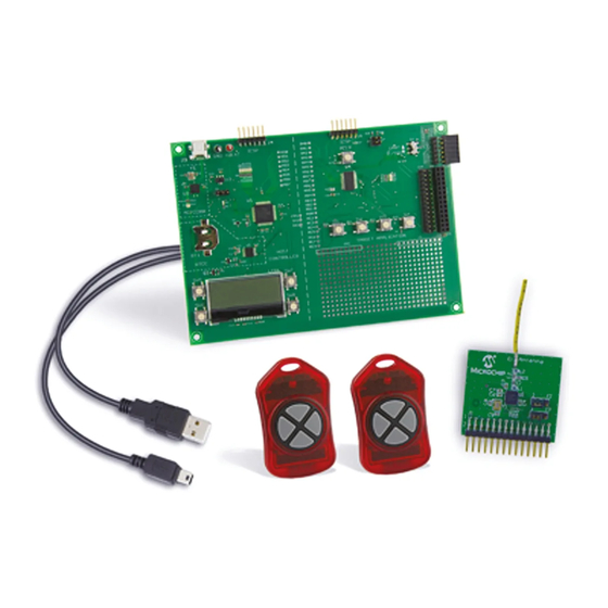
3. Plug in the RF receiver daughter board on the PICtail slot of the demo board. Make sure that the RF receiver daughter board has the side with the RF receiver chip facing the center, as shown in Figure 2-1. 2014 Microchip Technology Inc. DS40001746A-page 10... - Page 12 - To power from an external power supply, place jumper J6 to pins 2-3. Connect the test points labeled +V and GND to a bench power supply that is set to 3.3 V 2014 Microchip Technology Inc. DS40001746A-page 11...
-
Page 13: Operation
This kit is configured to transmit a Seed transmission with both buttons assigned to a particular encoder are pressed. The pairing phase also requires a Typical transmission to complete the pairing process. 2014 Microchip Technology Inc. DS40001746A-page 12... -
Page 14: Kee Loq Screens
LCD, as shown in Figure 2-3 and Figure 2-4. The type of transmission and the transmitter’s serial number are also displayed on the screen. OQ ® FIGURE 2-3: CLASSIC K ENCODER NOT LEARNED ® FIGURE 2-4: ULTIMATE K ENCODER NOT LEARNED 2014 Microchip Technology Inc. DS40001746A-page 13... - Page 15 TYPICAL TRANSMISSION DATA ® ‘ULT’ Indicates an Ultimate K encoder ‘12345666’ The encoder’s serial number ‘T: 00330A1F’ The encoder’s time-stamp ‘F: 04’ The encoder’s function code OQ ® FIGURE 2-6: TYPICAL ULTIMATE K TRANSMISSION 2014 Microchip Technology Inc. DS40001746A-page 14...
- Page 16 The receiver must complete the learn process within a fixed window. If the necessary data is not received from the transmitters within this window, the process will abort and a message similar to Figure 2-9 is displayed. FIGURE 2-9: LEARN MODE TIMEOUT 2014 Microchip Technology Inc. DS40001746A-page 15...
- Page 17 PAIRING COMPLETE A message similar to Figure 2-13 is shown if an otherwise valid Classic K packet is received, but is not a Seed transmission. ® FIGURE 2-13: CLASSIC K NO SEED TRANSMISSION 2014 Microchip Technology Inc. DS40001746A-page 16...
- Page 18 FIGURE 2-15: AUTHORIZATION CODE INVALID The kit allows the user to erase, or ‘forget’, all paired transmitters. If done, the LCD will display a message similar to Figure 2-16. FIGURE 2-16: DELETE EEPROM 2014 Microchip Technology Inc. DS40001746A-page 17...
-
Page 19: Chapter 3. Hardware Self-Test
Observe that the clock is advancing. Once the RTCC test is done, SW1 needs to be pressed to move forward to the SPI test. 2014 Microchip Technology Inc. DS40001746A-page 18... -
Page 20: Spi Test
Daughter Board, is plugged into the PICtail connector (even though the SPI bus may still be working), the SPI test might show failure status. The demo board expects an SX1239 to be identified on the SPI interface. 2014 Microchip Technology Inc. DS40001746A-page 19... -
Page 21: Chapter 4. Mcs3142 Wireless Remote Key Fob
The MCS3142 Wireless Remote Key Fob is a demonstration and development platform for wireless security remote control applications. Please see http://ww1.microchip.com/downloads/en/DeviceDoc/41646A.pdf for similar information about the transmitter printed circuit board and its antenna design. 2014 Microchip Technology Inc. DS40001746A-page 20... -
Page 22: Chapter 5. Embedded Security Development Board
USB Interface Port J3 PICtail™ Connector J1 16x2 character LCD display Real-Time Clock and Calendar (RTCC) module U5 Push Buttons LEDs Voltage Regulator ICSP™ Programming Ports, J4 for Host; J5 for Target Application 2014 Microchip Technology Inc. DS40001746A-page 21... -
Page 23: Serial Communications Connections
• 3 or 4-wire SPI • I C™ • USART Jumpers J7 and J8 connect pull-up resistors, typically useful when I C is selected and the pull-up resistors are not available on the daughter board. 2014 Microchip Technology Inc. DS40001746A-page 22... -
Page 24: Usb Interface Port
The RTCC module can be powered either by the 3.3V power from the Embedded Security Development Board, or by a separate coin battery when external power is not available. For details on operating this RTCC module, refer to the data sheet of the MCP795W10 at http://www.microchip.com/MCP795W10. 2014 Microchip Technology Inc. DS40001746A-page 23... -
Page 25: Push Buttons
USB power is selected; when the right side, pins 2-3 of J6 are closed, external power source is selected. When the USB port is used to power the board, the input voltage is stabilized by a Microchip MCP1703, LDO regulator U3. 2014 Microchip Technology Inc. DS40001746A-page 24... -
Page 26: Icsp™ Programming/Debugging Ports
Figure 5-3 shows the SX1239 Receiver PICtail Daughter Board. The schematic, PCB layout, and Bill of Materials are listed in Appendix B. “SX1239 Receiver PICtail™ Daughter Board Schematics”. FIGURE 5-3: SX129 PICtail™ DAUGHTER BOARD 2014 Microchip Technology Inc. DS40001746A-page 25... - Page 27 PCB. A whip or sleeve dipole antenna can then be used. If an SMA+ different antenna is used, the matching circuit will be less ideal. Pre-made antennas have a fixed, lower impedance. The wire used has a higher impedance. 2014 Microchip Technology Inc. DS40001746A-page 26...
-
Page 28: Chapter 6. Developing With The Mcs3142 Wireless Security Remote Control Development Kit 6.1 Introduction
PC interface. The developer should only need to develop on the target side. The prototyping area under the four push buttons for target application controller can be used to prototype the application. 2014 Microchip Technology Inc. DS40001746A-page 27... -
Page 29: Software Design
} else if (Decode_Advanced_KeeLoq(&inData) != NOT_VALID_PACKET) { //Custom code to interpret a valid Advanced Keeloq Packet. } else if (Decode_Ultimate_KeeLoq(&inData) != NOT_VALID_PACKET) { //Custom code to interpret a valid Ultimate Keeloq Packet. } else { validated_packet.type = INVALID_ENCODER; 2014 Microchip Technology Inc. DS40001746A-page 28... - Page 30 NVM Mediator The “nonvolatile” mediator provides access to the EEPROM where learned devices and their settings are saved. The developer should access this using the find(), write(), read() methods. 2014 Microchip Technology Inc. DS40001746A-page 29...
-
Page 31: Chapter 7. Kee Loq ® Mplab
FIGURE 7-1: SELECTING AN HCS200 K DEVICE IN STEP 2 OF THE NEW PROJECT CREATION INSIDE OF MPLAB X For more information about MPLAB X New Project Creation, please see the MPLAB X documentation. 2014 Microchip Technology Inc. DS40001746A-page 30... - Page 32 FIGURE 7-3: THE PLUGIN REQUIRES A MAIN PROJECT THAT HAS A OQ ® DEVICE SELECTED The device for this project can be easily modified by: (Right-Click) project-> Properties 2014 Microchip Technology Inc. DS40001746A-page 31...
-
Page 33: Export Sqtp
The utility can then output a file that can be sent to Microchip for production programming or used on a variety of Microchip and third party programmer tools. 2014 Microchip Technology Inc. DS40001746A-page 32... -
Page 34: File Format
EXPORT FILE DATA Format BBAAAATTHHHH..HHHCC 64-bit Key 0xB0B8C53F37D7 Synchronization 0x0000 Serial 0x00000000 Seed 0x177AA550 Configuration 0x0000 Please consult with your specific encoder data sheet for more information about the various key generation methods. 2014 Microchip Technology Inc. DS40001746A-page 33... -
Page 35: Generate Source
The user can now connect to the programmer and Flash a K device. To program the K device, simply click on the Make and Program Device Main Project button located on the MPLAB X toolbar. 2014 Microchip Technology Inc. DS40001746A-page 34... -
Page 36: Chapter 8. Pc Application
In order to be able to use the MCP2200 with Linux, the kernel must have support for USB CDC class drivers. For more information, Linux users should read the readme installation notes found here: http://ww1.microchip.com/downloads/en/Device- Doc/mcp2200_linux_driver_readme.txt. 2014 Microchip Technology Inc. DS40001746A-page 35... -
Page 37: Pc Quick-Start
In Windows, a notification stating that the MCP2200 device was installed and found successfully will show. If not, the MCP2200 driver may need to be installed manually as stated in the Section 8.2 “Installation”. 2014 Microchip Technology Inc. DS40001746A-page 36... - Page 38 SemTech data sheet for much more information regarding their receiver. Other settings such as learned devices and manufacturing numbers are also displayed and saved. The demo board should now display the version of the PC application on its LCD. 2014 Microchip Technology Inc. DS40001746A-page 37...
-
Page 39: Viewing Data
CLASSIC TABLE TAB UPDATED WITH A SINGLE LEARNED CLASSIC TRANSMITTER Not all of the columns are populated since those depend on the transmitter being active. The Graphic tab will also update with new data as seen below: 2014 Microchip Technology Inc. DS40001746A-page 38... -
Page 40: Normal Operation
The figures below show the two panels that have been updated after the previously learned device has its transmission received by the demo board. FIGURE 8-6: CLASSIC TABLE UPDATED WITH A SINGLE TRANSMISSION BY A PREVIOUSLY LEARNED DEVICE 2014 Microchip Technology Inc. DS40001746A-page 39... -
Page 41: Kee Loq Graphic Specifics
CLASSIC GRAPHIC UPDATED WITH A SINGLE TRANSMISSION BY A PREVIOUSLY LEARNED DEVICE 8.5.1 Graphic Specifics Each graphic contains a “Pie” on the right-hand side of the panel. Every K technology provides its own set of unique features. 2014 Microchip Technology Inc. DS40001746A-page 40... - Page 42 Storing the new synchronization counter value effectively rotates the entire Synchronization window. Note: The proportional aspects of the pie have been manipulated so that it is easier to view the fundamental operation 2014 Microchip Technology Inc. DS40001746A-page 41...
-
Page 43: Calculator
After applying the changes, the graphic will update itself from the new stimulus. Note that the effects are not saved to the transmitter, receiver, or inside the learned devices table. These changes do not persist between sessions. 2014 Microchip Technology Inc. DS40001746A-page 42... -
Page 44: Receiver Settings
1. AN1265 – K with AES Microcontroller-Based Code Hopping Encoder 2. DS41646 – Wireless Security Remote Control Development Kit User’s Guide ® 3. MCS3142 Dual K Encoder Data sheet 4. DS41378 – K 3 Development Kit 2014 Microchip Technology Inc. DS40001746A-page 43... -
Page 45: Appendix A. Mcs3142 Transmitter Fob Schematic
OQ ® MCS3142 DUAL K ENCODER WIRELESS REMOTE CONTROL DEVELOPMENT KIT USER’S GUIDE Appendix A. MCS3142 Transmitter Fob Schematic FIGURE A-1: KEY FOB SCHEMATIC 2014 Microchip Technology Inc. DS40001746A-page 44... - Page 46 Inductor Murata LQG15HSR12J02D 3 nH Inductor Murata LQG15HS3N0S02D 18 nH Inductor Murata LQG15HS18NJ02D 8.2 pF Capacitor Murata GRM1555C1H8R2CA01D 1.8 nH Inductor Murata LQG15HS1N8S02D 0 kW Resistor Yageo RC0402JR-070RL 26 MHz Crystal Abracon ABM8G-26.000MHZ-18-D2Y-T 2014 Microchip Technology Inc. DS40001746A-page 45...
- Page 47 Inductor Murata LQG15HSR15J02D 0 kW Resistor Yageo RC0402JR-070RL 12 nH Inductor Murata LQG15HS12NJ02D 2.7 pF Capacitor Murata GRM1555C1H2R7BA01D 0 kW Resistor Yageo RC0402JR-070RL 12 nH Inductor Murata LQG15HS12NJ02D 26 MHz Crystal Abracon ABM8G-26.000MHZ-18-D2Y-T 2014 Microchip Technology Inc. DS40001746A-page 46...
-
Page 48: Appendix B. Sx1239 Receiver Pictail™ Daughter Board Schematics
® MCS3142 DUAL K ENCODER WIRELESS REMOTE CONTROL DEVELOPMENT KIT USER’S GUIDE Appendix B. SX1239 Receiver PICtail™ Daughter Board Schematics FIGURE B-1: SX1239 RECEIVER PICtail™ PCB ASSEMBLY 2014 Microchip Technology Inc. DS40001746A-page 47... - Page 49 ® MCS3142 Dual K Encoder Wireless Remote Control Development Kit User’s Guide FIGURE B-2: RECEIVER PICtail™ SCHEMATIC 2014 Microchip Technology Inc. DS40001746A-page 48...
- Page 50 Switch, DPDT E-Switch EG1390A SX1239 RF Receiver Semtech SX1239IMLTRT 32 MHz Crystal 7M-32.000MEEQ-T 2.7 pF Capacitor Murata GRM1555C1H2R7CA01D 7.5 nH Inductor Murata LQG15HS7N5J02D 5.6 pF Capacitor Murata GRM1555C1H5R6DA01D Do not populate Do not populate 2014 Microchip Technology Inc. DS40001746A-page 49...
-
Page 51: Appendix C. Embedded Security Development Board Schematics
® MCS3142 DUAL K ENCODER WIRELESS REMOTE CONTROL DEVELOPMENT KIT USER’S GUIDE Appendix C. Embedded Security Development Board Schematics FIGURE C-1: EMBEDDED SECURITY DEVELOPMENT BOARD PCB ASSEMBLY 2014 Microchip Technology Inc. DS40001746A-page 50... - Page 52 Embedded Security Development Board Schematics FIGURE C-2: HOST CONTROLLER OF THE EMBEDDED SECURITY DEVELOPMENT BOARD SCHEMATIC 2014 Microchip Technology Inc. DS40001746A-page 51...
- Page 53 ® MCS3142 Dual K Encoder Wireless Remote Control Development Kit User’s Guide FIGURE C-3: TARGET APPLICATION OF THE EMBEDDED SECURITY DEVELOPMENT BOARD SCHEMATIC 2014 Microchip Technology Inc. DS40001746A-page 52...
- Page 54 GRM188R61A105MA61D B0520WS Diodes Inc. B0520WS-7-F — Fairchild Semiconductor BAT54 — Lite-On LTST-C191GKT — Lite-On LTST-C191GKT — Lite-On LTST-C191GKT — Lite-On LTST-C191GKT — Lite-On LTST-C191GKT — Lite-On LTST-C191GKT — Lite-On LTST-C191GKT — Lite-On LTST-C191GKT 2014 Microchip Technology Inc. DS40001746A-page 53...
- Page 55 Stackpole Electronics International RMCF0603FT330R 330 Stackpole Electronics International RMCF0603FT330R 330 Stackpole Electronics International RMCF0603FT330R 330 Stackpole Electronics International RMCF0603FT330R 330 Stackpole Electronics International RMCF0603FT330R 330 Stackpole Electronics International RMCF0603FT330R 2014 Microchip Technology Inc. DS40001746A-page 54...
- Page 56 Microchip Technology Inc. PIC16LF1947-I/PT MCP2200 Microchip Technology Inc. MCP2200-I/MQ MCP1703-3.3 Microchip Technology Inc. MCP1703T-3302E/MB PIC16LF1938-I/SS_28-PIN Microchip Technology Inc. PIC16LF1938-I/SS MCP795W10-I/ST Microchip Technology Inc. MCP795W10-I/ST 12 MHz NX3225SA-12.000000MHZ 32.768 kHz Abracon ABS06-32.768KHZ-T 32.768 kHz Abracon ABS06-32.768KHZ-T 2014 Microchip Technology Inc. DS40001746A-page 55...
-
Page 57: Worldwide Sales And Service
Tel: 86-29-8833-7252 Tel: 631-435-6000 Fax: 86-29-8833-7256 San Jose, CA China - Xiamen Tel: 408-735-9110 Tel: 86-592-2388138 Canada - Toronto Fax: 86-592-2388130 Tel: 905-673-0699 China - Zhuhai Fax: 905-673-6509 Tel: 86-756-3210040 10/28/13 Fax: 86-756-3210049 2014 Microchip Technology Inc. DS40001746A-page 56...
Need help?
Do you have a question about the DM182017-4 and is the answer not in the manual?
Questions and answers