Advertisement
Quick Links
Advertisement

Related Manuals for Centrometal CentroPlus 25


Summary of Contents for Centrometal CentroPlus 25
- Page 1 HEATING TECHNIQUE Centrometal d.o.o. - Glavna 12, 40306 Macinec, Croatia, tel: +385 40 372 600, fax: +385 40 372 611 TECHNICAL INSTRUCTIONS for installation, use and maintenance of hot water boiler and installation of additional equipment CentroPlus TU-CP-1-2022-ENG...
-
Page 2: Technical Data
Technical data TECHNICAL DATA CentroPlus 25 TYPE wood pellets Nominal heat output (kW) Heat output range (kW) 15-25 7,5-25 7,4-25 Boiler class Required chimney underpressure (Pa) Water amount in boiler Exhaust gas temperature at nominal heat output (°C) Exhaust gas temperature at minimum heat output (°C) - Page 3 Technical data CentroPlus 35 TYPE wood pellets Nominal heat output (kW) Heat output range (kW) 25-35 10,5-35 10-35 Boiler class Required chimney underpressure (Pa) Water amount in boiler Exhaust gas temperature at nominal heat output (°C) Exhaust gas temperature at minimum heat output (°C) Exhaust mass flow at nominal heat output (kg/s)
- Page 4 Technical data CentroPlus 50 TYPE wood pellets Nominal heat output (kW) Heat output range (kW) 35-49 14-49 14-49 Boiler class Required chimney underpressure (Pa) Water amount in boiler Exhaust gas temperature at nominal heat output (°C) Exhaust gas temperature at minimum heat output (°C) Exhaust mass flow at nominal heat output (kg/s)
- Page 5 Technical data Solid fuel CentroPlus 25/35 CentroPlus 25/35 CentroPlus 50 CentroPlus 50 Note: depending on the order, the boiler can be also delivered as left version. Technical instructions CentroPlus...
- Page 6 Technical data Solid fuel / EL fuel oil TEHNIKA GRIJANJA CentroPlus 25/35 CentroPlus 50 CentroPlus 50 CentroPlus 25/35 Note: depending on the order, the boiler can be also delivered as left version. Technical instructions CentroPlus...
- Page 7 Technical data Solid fuel / wooden pellets 08:42 TEHNIKA GRIJANJA CentroPlus 25/35 O F F O F F 08:42 08:42 CentroPlus 50 CentroPlus 50 CentroPlus 25/35 Note: depending on the order, the boiler can be also delivered as left version.
-
Page 8: Boiler Description
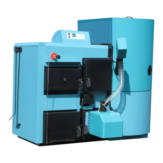
WHICH IS INSTALLED TO CLOSED CENTRAL HEATING SYSTEM CentroPlus 25/35: - thermal valve (such as CALEFFI 543) -1 piece CentroPlus 50: - thermal valve (such as CALEFFI 543) -2 pieces - thermal protection exchanger Centrometal - 2 pieces Technical instructions CentroPlus... - Page 9 Additional boiler equipment, positioning and assembly 1.4. ADDITIONAL EQUIPMENT FOR THE BOILER CentroPlus 25/35 Depending on preferred boiler use it is necessary to install appropriate additional equipment to the boiler: 1) Additional equipment for solid fuel / wooden pellet firing: - pellet burner CPPL-35, digital boiler control unit CPREG for pellet burner CPPL-35;...
- Page 10 Boiler positioning and assembly 2.1. SOLID FUEL FIRED BOILER (EQUIPMENT FOR WOODEN PELLETS AND OIL IS NOT BUILT-IN YET) Draft controller has to be installed to the boiler left side (such as CALEFFI 543, ESBE ATA200) and connect it by a chain to the movable lid on the boiler lower door. The electrical connector and heating pump connect according to the electrical scheme (Scheme 5.).
- Page 11 Installation of casing Figure 2. Installation of the casing to the boiler Bracket X (the boiler front holders 08:42 side) Bracket Y 4,2x32 (the boiler back (4x) side) Middle bracket 4,2x32 (the boiler front side) 4,2x32 4,2x32 Detail 1. (3x) side 5 3,9x9,5 (3x)
-
Page 12: Connection To The Chimney
Opening for fresh air, connection to the chimney 3.0. OPENING FOR FRESH AIR Each boiler room must have an opening for fresh air supply which is dimensioned in accordance with boiler output (minimum opening area according to the below shown formula). The opening must be protected with a net or a grate. - Page 13 Connection to the chimney, installation to the central heating system Figure 4. Chimney dimensioning for the boiler CentroPlus An example of a chimney selection: - Boiler heat output: 50 kW - Fuel: Wood, wooden pellets, EL fuel oil - Required usable chimney height: H = 8 m - Required light chimney diameter: 25 cm - Useful chimney height - chimney height from connection spot of smoke tube to the...
- Page 14 Boiler installation to the closed heating system 5.1. BOILER INSTALLATION TO THE CLOSED HEATING SYSTEM In the closed heating system (an example that is shown in Scheme 1a and 1b) it is obligatory to install certified safety valve with opening pressure of 2,5 bar, minimum seat diameter of 15 mm, minimum inlet connection of 1/2", minimum exit connection of 3/4"...
- Page 15 - the thermal exchanger connector 7 connect into the sawage - into the coupling 1 (internal thread 1/2") twist the thermal valve sensor (outer thread 1/2"). Scheme 2. The thermal protection installation to the boiler CentroPlus 25/30 that is installed to the closed heating system...
- Page 16 Boiler thermal protection 5.1.2. THE BOILER THERMAL PROTECTION - CentroPlus 50 The boiler is factory prepared for installation of thermal protection ( two heat exchangers 1 and two thermal valves 2 (such as CALEFFI 543) (see Scheme 2.1.). In case of any damage of the boiler which is installed to the closed heating system due its overheating, and if boiler and system are not equipped with thermal protection or if it is not properly installed, guarantee will not be applied.
- Page 17 If the open expansion vessel is placed into the unheated room, it is necessary to isolate it. An example of installation the boiler CentroPlus 25/35 to the open heating system (solid fuel/wooden pellets firing is presented, installation for the other types is the same ) Scheme 3a.
- Page 18 Boiler installation to the open heating system An exaple of installation the boiler CentroPlus 50 to the open heating system (solid fuel/wooden pellets firing is presented, installation for the other types is the same) Scheme 4a. An example of installation of the accumulation tank to the central heating system required according to the EN 303-5 norm ABOVE THE HIGHEST HEATING BODY to the boiler...
- Page 19 Boiler temperature regulation 6.0. THE BOILER TEMPERATURE REGULATION 6.1. SOLID FUEL FIRING (EQUIPMENT FOR WOODEN PELLETS OR OIL IS NOT INSTALLED) The draft controller (such as CALEFFI 543, ESBE ATA200) is needed for the boiler temperature regulation, and it has to be is installed on the boiler front left side (see page 5.). The draft controller chain has to be adjusted in a way that boiler temperature do not exceed the temperature from 85 to 90°C by normal firing (opening for air is completely closed), and not drop under 65°C.
- Page 20 Boiler temperature regulation 6.3.2. EL FUEL OIL FIRING Temperature in boiler is controlled by boiler control unit EKO-CK/CKB which is installed to the boiler lid (see page 6). On boiler control unit EKO-CK/CKB the burner has to be switched on (Figure 5, position 1) and it is necessary to adjust the regulation thermostat to the preferred boiler temperature (70-90°C).
- Page 21 Boiler connection to the electrical installation 7.0. BOILER CONNECTION TO THE ELECTRICAL INSTALLATION All electrical works must be done by qualified person and according to the valid national and European standards. A device for switching off all power supply poles must be installed to the electrical installation in accordance with the national regulations for electrical installations.
-
Page 22: Oil Burner
Boiler connection to the electrical installation Scheme 6. Electrical scheme of the boiler control unit EKO CK/CKB for solid fuel/oil and the pump thermostat Electrical scheme of the boiler control unit EKO CK/CKB for solid fuel/oil SUPPLY PUMP OIL BURNER 230 V CONNECT TO THE 4-PIN PLUG NOTE: The socket is placed in... - Page 23 Startup 8.0. STARTUP Check if the boiler and equipment are installed and connected in accordance with these Technical instructions (check all points, from the point 1.0. till the point 8.0.). Check also if the chimney and boiler room meet all requests from the point 4 (described in these technical instructions). Check if the fuel meets all requests from these instructions.
- Page 24 Startup Check if the shut-off valves toward the heating bodies are opened. If you are sure that energy from boiler will be consumed, made firing up for one filling of the firebox: - put tiny wood (moisture content max 25%), crumpled paper and then tiny wood again. Close the upper boiler door and ignite the wood and paper through the lower door - after tiny wood blaze up, close the lower door and through upper boiler door put some dry smaller logs (moisture content max.
- Page 25 Startup 8.2.1. WOODEN PELLETS CHARACTERISTICS Wooden pellets are used as a fluel in boilers with built-in pellet burner CPPL. Wooden pellets are biofuel made of wooden residual. Pellets can be packed in different packaging: in bags (15 kg, 1000 kg) or as bulk in a large (underground) tank (4-15 m ) or in basement rooms.
-
Page 26: Boiler Use
Boiler use 9.0. BOILER USE The boiler must not operate in flammable and explosive environment. Children or disabeled persons (either physically or mentally), as well as person without knowledge or experience are not allowed to use the boiler, unless they are under control or trained by a person responsible for their safety. Children must be supervised in the vicinity of the boiler. -
Page 27: Boiler Cleaning And Maintenance
Boiler use, cleaning and maintenance Before adding fuel into the firebox, the door has to be firstly kept slightly open (about 1 cm) 3 to 5 seconds, and then you can fully open the door. Pellet firing. Check if the movable parts of the right firebox are placed to the intended place (right firebox lid, burner grate, righ firebox ashtray, turbolators placed into the flue gas tubes and back ashtray box) Figure 7. - Page 28 Boiler cleaning and maintenance 10.1. SOLID FUEL FIRED BOILER (EQUIPMENT FOR WOODEN PELLETS IS NOT INSTALLED YET) It is necessary to clean space below the grate, firebox and flue gas tubes on daily basis. The flue gas tubes are cleaned through the upper door, but firstly remove movable lid placed between the middle and upper register (upper lid).
- Page 29 Boiler cleaning and maintenance 10.3. BOILER FIRED WITH SOLID FUEL / EL FUEL OIL It is recommended to check all control and safety elements and also oil burner with additional equipment once a year by a certified serviceman. Firebox for solid fuel firing: First, the main switch at boiler control unit has to be switched off.
- Page 30 Notes Technical instructions CentroPlus...
- Page 31 Notes Technical instructions CentroPlus...
- Page 32 Company assumes no responsibility for possible inaccuracies in this book originated typographical errors or rewriting, all figures and diagrams are principal and it is necessary to adjust each actual situation on the field, in any case the company reserves the right to enter their own products such modifications as considered necessary. Centrometal d.o.o. Glavna 12, 40306 Macinec, Croatia central tel: +385 40 372 600, fax: +385 40 372 611 service tel: +385 40 372 622, fax: +385 40 372 621 www.centrometal.hr...
Need help?
Do you have a question about the CentroPlus 25 and is the answer not in the manual?
Questions and answers