Table of Contents
Advertisement
Quick Links
Advertisement
Table of Contents

Related Manuals for Centrometal BioTec Plus 25


Summary of Contents for Centrometal BioTec Plus 25
- Page 1 HEATING TECHNIQUE Centrometal d.o.o. - Glavna 12, 40306 Macinec, Croatia, tel: +385 40 372 600, fax: +385 40 372 611 TECHNICAL INSTRUCTIONS for installation, use and maintenance of hot water boiler and installation additional equipment BioTec Plus TUBTP-01-2018-eng...
- Page 2 These instructions are an integral part of this product. All rights reserved. Reproduction of content of this document and transfer to third parties is not allowed without written approval from manufacturer. Make sure the instructions are always with the device, even if its sale / transfer of another owner to the user or staff authorized for maintenance or repairs to consult.
- Page 3 BioTec Plus Nominal heat output (kW) Heat output range (wood) (kW) 12,5-25 17 -3 ,5 5 22,5-45 7,5-25 10,2-35 13,5-45 Heat output range (wood pellets) (kW) Boiler class (wood / wood pellets) Required chimney underpressure (Pa) Water amount in boiler (lit.) Exhaust gas temperature at nominal heat output (wood) (°C)
- Page 4 BioTec Plus 25 / 35 INNER PARTS VIEW FOR BOILERS BioTec Plus 25-45 Boiler dimensions BioTec Plus 25 BioTec Plus 35 BioTec Plus 45 Depth 1605 1450 1450 Width 1055 1255 1260 Height 1350 1450 1585 Other dimensions (C1) 1260...
- Page 5 BioTec Plus 45 DM - Flue gas tube connection SV - Middle boiler door (wood) DO - Cover of lower openings of the flue gas chamber TI - Heat exchanger output (safety DS - Lower refractory stone (chamotte) (2 parts) cooling system) (pellet) DV - Lower boiler door (wood) TO - Thermal safety valve sensor...
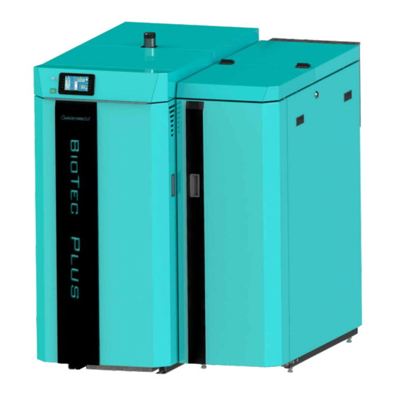
- Page 6 1.0. GENERAL Steel hot water boiler BioTec Plus has two separate combustion chambers inside the common boiler water chamber. Boilers BioTec Plus, nominal heat output 25, 35 and 45 kW, are designed for wood log firing in left part and wood pellet firing in right part of the boiler. The wood gasification principle enables a complete fuel burning in left part of the boiler.
-
Page 7: Safety Precautions
Concerning the specific need of sanitary hot water, the BioTec Plus boiler can be connected to one of water heaters produced by our company. We suggest the combination with wall hanged SKB Digi or LKB Digi water heaters, as well as with floor standing TB water heaters or accumulation tanks CAS-B. - Page 8 1.4. WOOD GASIFICATION COMBUSTION PROCESS (wood side) Combustion process is carried out in double combustion chamber in several phases. After filling the upper chamber with logs, glow dry the logs, and at temperature 100÷300°C logs are beeing gasified. The gases created in such process are mixed with the oxygen from air and burn out completely with high temperature.
-
Page 9: Delivery Package
2.0. DELIVERY PACKAGE Boiler BioTec Plus is delivered in parts for easier transportation and mounting to boiler room. Basic equipment is delivered seperately: - left part of the boiler for wood firing with mounted thermal insulation (on wood pallet) with inbuilt: - color touch screen display control unit - sensor in combustion chamber... -
Page 10: Additional Equipment
2.1. ADDITIONAL EQUIPMENT Additional equipment is not included in basic delivery. Obligatory additional equipment must be purchased seperately. Other additional equipment can be purchased optionally. 1) OBLIGATORY ADDITIONAL EQUIPMENT: - accumulation (buffer) tank for heating system (CAS (min. liter according to local regulation), inimum 50 litres / kW of boiler - return flow protection - 3-way mixing valve with actuator (protection valve) or 3-way thermostat valve (60°C) (like ESBE VTC 512, VTC 531, LTC 261, LTC 271). - Page 11 3.0. BOILER / ADDITIONAL EQUIPMENT POSITIONING AND ASSEMBLY The positioning of the boiler has to be carried out the authorized person. We suggest the positioning on the solid concrete basis, which height is between 50-100 mm. The boiler room has to be absolutely protected from freezing and properly ventilated.
- Page 12 3.1. INSTALLATION OF DELIVERED PARTS BioTec Plus is delivered on two wooden pallets. It must be mounted like is described on next pages of these technical instructions. After the boiler is mounted, should be positioned in the boiler room (see point 2.0.). Base protection with stone wool push under the boiler as shown in figure 2.a.
- Page 13 CONNECTING LEFT AND RIGHT SIDE OF THE BOILER Detail 1 Detail 2 Right part of the boiler Left part of the boiler (fuel: wood pellets) (fuel: wood) Detail 1 Detail 2 Prepared flange with holes on left part Prepared flange on right side of the of the boiler.
- Page 14 STEP 1: BioTec Plus - left part of the boiler section view Sheet metal protection cover Remove sheet metal protection cover through the upper boiler door. STEP 2: It’s necessary draw closer left side of the boiler to right side of the boiler. Screws from flange on right side of the boiler must get into flange holes on left side of the boiler.
- Page 15 BioTec Plus - left part of the boiler section view A - hole with circle shape; other holes are slitted for height niveling possibility. Screws from flange on right side of the boiler must get into flange holes on left side of the boiler like is showned on figure above.
- Page 16 STEP 4: BioTec Plus - left part of the boiler section view Put washers, toothed washers and nuts on all other screws and start tigth them. If is needed, nivel boiler (holes are slitted for niveling). Thight hard all six nuts. STEP 5: Left and right side of the boiler have adjustable foots.
- Page 17 STEP 6: prepared sockets on left side prepared plugs on right side of the boiler (wood) of the boiler (wood pellets) On left side of the boiler (wood) are prepared sockets, on right side of the boiler (wood pellets) are prepared plugs. Cabels must be connected in right order: 1-1;...
- Page 18 Figure 2.a Base protection with mineral wool Push base protection under the boiler Figure 2.b Delivered parts Sensor set Cleaning set Position od cleaning set - on the boiler. Position od cleaning set - on the wall. Technical instructions BioTec Plus...
-
Page 19: Connection To The Chimney
Figure 3. - Possible connecting of the BioTec Plus boiler to the chimney Possible way of connecting to the Possible way of connecting chimney of the BioTec Plus 25-35 boiler to the chimney of the Bio-Tec-L boiler (recommendation) (Only BioTec Plus 45 because of position... - Page 20 Figure 4. Figure 4. Incorrect connecting the boiler to the chimney - not possible cleaning of the fan BioTec Plus 45 BioTec Plus 25 / 35 Flue gas elbow Flue gas tube Figure 5.
- Page 21 4.1. FRESH AIR OPENING Boiler room must be equipped with an opening for supply of fresh air which is dimensioned in accordance with boiler thermal output (minimum opening area according to below shown equation). Such opening must be protected with a net or grate. All installation works have to be performed in accordance with valid national and European standards.
-
Page 22: Connection To The Central Heating System
5.0. CONNECTION TO THE CENTRAL HEATING SYSTEM All installation works must be made in accordance with valid national and European standards. Boiler BioTec Plus can be built to closed and open central heating system. In both cases boiler must be fired with wood logs or wood pellets. Installation has to be made in according to technical standards, by a professional who will be responsible for proper boiler operation. - Page 23 Scheme 1a. - Basic scheme for boiler instalation on closed central heating system with return flow protection with thermic valve (group) (electrical connections and sensor are not drawn, for details see general schemes) 05:08 xx°C -°C 20.0°C xx°C xx °C 20.0-0.0°C 25.0°C xx°C...
- Page 24 5.1. CONNECTION TO THE OPEN CENTRAL HEATING SYSTEM If the boiler is aimed to be integrated into an open central heating system, one of possible way how to connect the boiler to the system is shown on Scheme 1b. In case of BioTec Plus boilers, the boiler pump obligatory has to be connected to the boiler control unit, in order to make turning on and off of the pump depending on the temperature of the water in the boiler, to avoid boiler condensation.
-
Page 25: Boiler Thermal Protection
5.2.1. BOILER THERMAL PROTECTION According to European EN standards, boiler thermal protection must be installed in closed heating system. Boiler is factory prepared for installation of thermal protection. Heat exchanger is factory installed on left side of the boiler (wood), and thermal safety valve (7) should be installed according to Scheme 2. - Page 26 Scheme 2. - Thermal protection in an closed heating system 1 - Heat exchanger connection (to thermal safety valve) (left side of the boiler - wood) 2 - Connection for the thermal safety valve sensor (left side of the boiler - wood) 3 - Heat exchanger connection (to the sewerage) (left side of the boiler - wood) 4 - Thermal safety valve connection...
- Page 27 5.3. GENERAL CONNECTION SCHEMES Each heating scheme with BioTec Plus has option of installing up to 4 pcs CM2K-B modules (additional heating circuits management, DHW preparation and recirculation). Scheme 3. - General scheme of closed central heating system with 2 or more accumulation tanks. P1 - PumpP1 (boiler pump) 1 - Boiler "BioTec Plus"...
- Page 28 Scheme 4. - General scheme of closed central heating system with 1 accumulation tank, boiler return flow protection with 3 - way mixing valve with electric actuator. 1 - Boiler "BioTec Plus". P1 - Pump P1 (boiler pump) 2 - "CAS" accumulation tank (buffer tank). A - Accumulation tank sensor (upper) 3 - Return flow protection (3-way mixing valve with actuator B - Accumulation tank sensor (lower)
- Page 29 Scheme 5.- General scheme of closed central heating system with 1 accumulation tank and DHW preparation in front behin accumulation tank IMPORTANT! This way of connecting DHW tank is neccesary if in some part of the year we only want to use pellets for heat DHW tank. 1 - Boiler "BioTec Plus".
- Page 30 Scheme 6. - General scheme of closed central heating system with 1 accumulation tank, heating system behind accumulation tank, 1 heating circuit with 3-way mixing valve with actuator (or without actuator), and DHW preparation. P1 - Pump P1 (boiler pump) 1 - Boiler "BioTec Plus".
- Page 31 Scheme 7. - General scheme of closed central heating system with 1 accumulation tank, heating system in front of accumulation tank, 1 heating circuit with 3-way mixing valve with actuator, room corrector, and DHW preparing. 1 - Boiler "BioTec Plus ". P1 - Pump P1 (boiler pump) 2 - "CAS"...
- Page 32 Scheme 8. - General scheme of closed central heating system with 1 accumulation tank, heating system behind accumulation tank, 2 heating circuit with 3-way mixing valve (one with actuator, other manually operated). P1 - Pump P1 (boiler pump) 1 - Boiler "BioTec Plus". P2 - Pump P2 (heating pump circuit 2) 2 - "CAS"...
- Page 33 Scheme 9. - General scheme of closed central heating system with 1 accumulation tank, heating system behind accumulation tank, 3 heating circuit with 3-way mixing valve and DHW preparing. 1 - Boiler "BioTec Plus". F - CM2K -B module (can be expanded to P1 - Pump P1 (boiler pump) 2 - "CAS"...
- Page 34 Scheme 10. - General scheme of closed central heating system with 1 accumulation tank, hydraulic crossover behind accumulation tank, 2 heating circuits with 3-way mixing valve with actuator managed by CM2K-B module, DHW preparing. 1 - Boiler "BioTec Plus". P1 - Pump P1 (boiler pump) F - CM2K -B module (can be expanded to 2 - "CAS"...
- Page 35 Scheme 11. - General scheme of closed central heating system with 1 accumulation tank, hydraulic crossover behind accumulation tank, 3 heating circuits with 3-way mixing valve with actuator (1 direct heating circuit and 2 circuits managed by CM2K-B module). 1 - Boiler "BioTec Plus". P1 - Pump P1 (boiler pump) F - CM2K -B module (can be expanded to 2 - "CAS"...
- Page 36 Scheme 12. - General scheme of closed central heating system with 1 accumulation tank, custom heating system 1 - Boiler "BioTec Plus". P1 - Pump P1 (boiler pump) 2 - "CAS" accumulation tank (buffer tank). A - Accumulation tank sensor (upper) 3 - Return flow protection (3-way mixing valve with actuator B - Accumulation tank sensor (lower) (protection valve) or 3-way thermic valve (60°C),...
- Page 37 6.0. BOILER REGULATION 6.1. BOILER CONTROL The boiler is controlled with electronic control unit, built in the upper part of the boiler, below upper casing. Control unit controls boiler functioning, one heat circuit through 3 way mixing valve with actuator and outer temp.
-
Page 38: Electric Connection
7.0. ELECTRIC CONNECTION All electrical works must be performed by a certified professional in accordance with valid national and European standards. A device for switching of all power supply poles must be installed in electrical installation in accordance with the national regulations on electrical installations. CAUTION: When connecting any electrical part be sure to unplug the boiler at the main switch and disconnect the power supply. - Page 39 Technical instructions BioTec Plus...
- Page 40 Technical instructions BioTec Plus...
- Page 41 Technical instructions BioTec Plus...
- Page 42 Technical instructions BioTec Plus...
- Page 43 Technical instructions BioTec Plus...
- Page 44 Technical instructions BioTec Plus...
- Page 45 Technical instructions BioTec Plus...
- Page 46 7.1. BOILER SENSORS AND PROBES - Boiler temperature sensor (NTC 5K) (left side of the boiler; fuel: wood) - Boiler temperature sensor (NTC 5K) (right side of the boiler; fuel: wood pellets) - Combustion chamber temperature sensor (thermo couple) - Flue gas sensor (PT1000) - Fan RPM sensor - Lambda probe - Outer temperature sensor (NTC 5K)
- Page 47 RESISTANCE LIST NTC 5k/25°C SENSOR RESISTANCE LIST NTC Pt1000 SENSOR (measuring field from -20 - +130 °C) (measuring field -30 - +400 °C) Temperature Temperature Resis. Temperature Resis. Resistance (°C) (°C) (°C) ( W ) ( W ) 48.534 1.866 36.465 27.665 1.886...
-
Page 48: Boiler Use
8.0. BOILER USE Boiler must not be used in flammable and explosive environment. It must not be used by children or disabled persons (either physically or mentally), as well as by person without knowledge or experience, unless they are under control or trained by s person responsible for their safety. - Page 49 8.1. BOILER CONTROL UNIT USE 8.1.1. BUTTONS Button ’’ON / OFF’’ Button ’’OK’’ options: on / off boiler operation’’ Button ’’DISPLAY SELECTION’’ Button ’’START’’/’’STOP’’ options: main menu / work Button ’’BOILER OPERATION DISPLAY’’ Navigation buttons: options: graphic / numeric ’’LEFT’’, ’’RIGHT’’, ’’UP’’, ’’DOWN’’ Button ’’DELETE’’...
- Page 50 8.1.2. SYMBOLS Pump (when pump is working symbol is rotating, otherwise idle) The pump has a request for work (next to the pump symbol bright yellow square when the consumer given the demand for work the pump, the pump does not work if you have not met all the conditions for work, for example.
-
Page 51: Main Screen
8.1.3. MAIN SCREEN 13 14 19 20 1a - Boiler (Wood firing side) 11 - Combustion chamber temperature 1b - Boiler (Pellet firing side) 12 - Flue gas temperature 2 - Buffer tank 13 - The percentage of oxygen in the flue gases 3 - Boiler pump P1 (lambda probe) 4 - 3 - way protection valve... -
Page 52: Main Menu
8.1.4. MAIN MENU Main menu on BioTec Plus boiler control unit is composed of two parts - changeable part (1a and 1b) and static part (2). By pressing button for change fuel (see image below) displayed parameter will be changed. Displaying parameters can be changed regardless of boiler working phase and which fuel are choosen as active for work. - Page 53 8.1.5. CHOOSING BOILER SIDE (choosing fuel) Using of BioTec Plus boiler are consist of using of left part of the boiler (fuel: wood) and using of right part of the boiler (fuel: wood pellets). On boiler control unit is necessary to choose which side of the boiler will be used (which fuel will be used).
- Page 54 8.1.6. TAKING OVER Note: Option „Taking over” is possible only from left side of the boiler (fuel: wood) to right side of the boiler (fuel: wood pellets) (wood pellets taking over wood). „Taking over” option is used for automatic switching operation from one fuel to another fuel. Automatic switch is possible only from wood to wood pellets.
- Page 55 a) activating „Taking over” option through main screen (boiler side activity indicator) Hold this button for 3s! Hold this button for 3s! Press green activity indicator on right boiler side (fuel: wood) and hold it for 3 seconds. On display will be desplayed „Do you want to ENABLE „pellets take over?”.
- Page 56 8.2. USE THE LEFT SIDE OF THE BOILER - FUEL: WOOD 8.2.1. IGNITION Boiler must not be used in flammable and explosive environment. It must not be used by children or disabled persons (either physically or mentally), as well as by person without knowledge or experience, unless they are under control or trained by s person responsible for their safety.
- Page 57 - if this message is shown on display than wait for primary and secondary air actuators Primary and secondary wings - primary and secondary air is ready for work when indicator seeking initial position. Please stop blinking wait and try again. Primary and secondary air indicators.
- Page 58 - on display is displayed message "IGNITION 2/3" - on this step is neccessary to wait until flue gas temperature raise 50°C - middle boiler door must be opened all time - when is flue gas temperature higher than 50°C press ”enter“ button - on display is displayed message "IGNITION 3/3"...
- Page 59 Additional: During ignition phase is possible to see main display. It is neccessary to press button. Because ignition phase is on proces, display will be displayed current ignition step to (1). By pressing button we return to full preview of ignition phase. Technical instructions BioTec Plus...
- Page 60 8.2.2. REFILLING Boiler must not be used in flammable and explosive environment. It must not be used by children or disabled persons (either physically or mentally), as well as by person without knowledge or experience, unless they are under control or trained by s person responsible for their safety. Children must be supervised in the vicinity of the product.
- Page 61 ACTION: Press button „START / STOP“, on display will be displayed window with offered options „NEW LOADING“ and „OFF“. Press button NEW LOADING „NEW LOADING“. GLW2 On display is displaying boiler operating phase „SP1". Description of the refilling wood loading chamber: - open upper boiler door (see pages 4 i 5 in this technical instructions).
- Page 62 PROCEDURE IF GLOW IS NOT ENOUGH GOOD If glow is not enough good for fuel refilling folow the next steps: ACTION: Press button „START / STOP“, on display will be displayed window with offered options NEW LOADING „NEW LOADING“ and „OFF“. Press button „OFF.
- Page 63 8.3. USE THE RIGHT SIDE OF THE BOILER - FUEL: WOOD PELLETS Boiler must not be used in flammable and explosive environment. It must not be used by children or disabled persons (either physically or mentally), as well as by person without knowledge or experience, unless they are under control or trained by s person responsible for their safety.
- Page 64 BOILER STOP: For boiler stop is neccesary to press ON / OFF button. After pressing ON / OFF button on display will be displayed window for boiler stop confirmation. Press „OK” to confirm boiler stop. Technical instructions BioTec Plus...
- Page 65 8.3.1. REFFILING OF WOOD PELLETS Wood pellet is manual filling on right upper side of the boiler (pellet part) (see figure below). It’s necessary to open casing cover using the handle. IMPORTANT: At filling wood pellet tank it must be filled at least 2/3 of capacity for correct work of wood pellet level sensor! Technical instructions BioTec Plus...
- Page 66 x.x.x. TEMPERATURE ADJUSTMENT 8.4. TEMPERATURE ADJUSTMENT Temperature adjustment are performed seperately for left (fuel: wood) and right (fuel: wood pellets) side of the boiler. For adjustment left side of the boiler (fuel: wood) temperature it’s necessary to choose menu for wood firing (WOOD(w)). For adjustment right side of the boiler (fuel: wood pellets) temperature it’s necessary to choose menu for wood pellet firing (PELLETS(p)).
- Page 67 4. DHW temperature (depend about DHW configuration) In this submenu is possible to adjust domestic hot water temperature. - Factory adjusted: 50°C - Adjustment range: 40°C - 80°C 5. Differential of DHW (depend about DHW configuration) In this submenu is possible to adjust differential of domestic hot water temperature. - Factory adjusted: 5°C - Adjustment range: 4°C - 40°C 6.
- Page 68 TEMPERATURE ADJUSTMENT FOR WOOD PELLET FIRING Fuel: Wood pellets This submenus depend about DHW configuration Submenus: 1. p.Maximal boiler temperature In this submenu is possible to adjust maximal boiler working temperature. - Factory adjusted: 80°C - Adjustment range: 70°C - 90°C 2.
- Page 69 5. Minimal buffer tank temperature In this submenu is possible to adjust buffer tank temperature. - Factory adjusted: 20°C - Adjustment range: 5°C - 85°C 6. DHW temperature (depend about DHW configuration) In this submenu is possible to adjust domestic hot water temperature. - Factory adjusted: 50°C - Adjustment range: 40°C - 80°C 7.
-
Page 70: Cleaning And Maintenance Of The Boiler
9.0. CLEANING AND MAINTENANCE OF THE BOILER Every millimeter of soot and dirt on the surfaces of the boiler surface means approx. 5% higher fuel consumption. Save fuel – clean the boiler on time! PROTECTIVE GLOVES ARE OBLIGATORY!!! DESCRIPTION OF MAINTENANCE INTERVAL Cleaning ash in firebox and under firebox (through Before each ignition. - Page 71 Boiler type Description Cleaning / maintenance interval Cleaning ash in firebox and under firebox (through middle and lower door - left part Before each ignition 25, 35 and 45 kW of the boiler) and ash tray emptying from right part of the boiler. Before every ignition is necessary to clean area below firebox and lower refractory stone (DS) (through middle and lower boiler door (DV)) and empty ashtray (PA) from the right...
- Page 72 Cleaning / maintenance interval Boiler power Description Check the correctness of security Every 6 months 25, 35 and 45 kW valve Checking the correctness of security valve By briefly turning the cap of safety valve (C) check whether water coming out from the safety valve.
- Page 73 Cleaning / maintenance interval Boiler power Description Cleaning of area over heat At least once per year 25, 35 and 45 kW exchanger pipes with turbulators 1 - Switch off the boiler and disconnect from electric. power. 2 - Take out last upper cover side. 3 - Open the flue gas chamber.
- Page 74 25, 35 and 45 kW At least once per year the fan BioTec Plus 25, 35 1. Switch off the boiler and disconnect from electric. power. 2. Unscrew nuts (A) shown in Image 1. 3. Relase screws (B) shown in Image 2.
- Page 75 Cleaning / maintenance interval Boiler type Description At least once a year (or if you have problems 25, 35 and 45 kW Photocell cleaning with the ignition) Dirty photocell which can result Valid photocell error in ignition or flame dissapear error Carefully remove the photocell from the box and then gently with a cotton swab clean the body and lens of photocell.
- Page 76 10.0. MALFUNCTIONS 10.1 ERRORS/WARNINGS/INFORMATIONS ON THE MAIN SCREEN When the error/warning still present, error/warning name and code is painted red, and when error/warning is resolved, text turns green Error / Warning / Information code Error / Warning / Information name Date and time of error / warning / information occurrence Number of errors / warnings / informations „OK”...
- Page 77 10.2. HISTORY By pressing on „History” button will be opened menu for choosing history list. It can be choosen between error list and warning list. Informations history are placed with error list. Written is: - time of occurrence errors / warnings / informations - error / warning / information code - description of the error / warning / information.
-
Page 78: Error List
10.3. ERROR LIST MUTUAL ERRORS (WOOD / WOOD PELLETS): ERROR NAME DESCRIPTION Boiler status: Boiler go to phases S7, C0 and OFF. Possible causes:Interruption on el. connections between DHW sensor error sensor and boiler, connection to the boiler, cold connection or DHW sensor is invalid. Boiler status: Boiler go to phases S7, C0 and OFF. - Page 79 Boiler status: Boiler immediate go to phase OFF. Communication error with Possible causes: Call service man! motherboard Boiler status: Boiler go to phases S7, C0 and OFF. Communication error with Possible causes: Call service man! sensor board a) Error occurs in the phase of "OFF" The problem is with el.
- Page 80 Boiler status: Boiler work normally. Hydraulic crossover Possible causes: Interruption on el. connections between sensor error room corrector and boiler, connection to the boiler or hydraulic crossover sensor is invalid. Boiler status: Boiler work normally. Communication error with Possible causes:Interruption in el. connections between CM2K module (3rd and boiler and CM2K (between two CM2K’s), connection on E16_1...
- Page 81 Boiler status: Pump of 6+ heating circuit work in intervention mode by heating curve. Boiler work normally. Corrector reg. 6. circuit Possible causes: E20_2 Error on room corrector of 6+ heating circuit (CM2K regulator), bad corrector connection to the CM2K or room corrector failure.
- Page 82 WOOD FIRING ERRORS: ERROR NAME DESCRIPTION Boiler status: Boiler work normally. Intervention mode: Boiler work to content heating demand Firebox sensor Ew21 but boiler has reduced possibilities. Possible causes: Invalid firebox sensor. WOOD PELLETS FIRING ERRORS: ERROR NAME DESCRIPTION Boiler status: Boiler go to phase OFF after ending phase S0 (retry start is allowed).
- Page 83 Boiler status: Boiler work normally. Possible causes: Check the pellet level in the big Ep41 No pellets tank/room , check if the flexible tubes are blocked, check if the turbine net is full with dust. Boiler status: Boiler work normally. Possible causes: Check the electric connections on the Ep42 Mole or screw not working...
-
Page 84: Warning List
10.4. WARNING LIST MUTUAL WARNINGS (WOOD / WOOD PELLETS): WARNING NAME DESCRIPTION Factory settings loaded. Factory setting loaded Appear always when fan decrease rotating speed or if Fan protection turning ”OFF“ itself because of high flue gas temperature. Intervention work The boiler operates without using the firebox sensor. - Page 85 Fan is OFF, flue gas Too high flue gas temperature with the open upper boiler temperature is to high. door. Close the uper door and restart the boiler (load fuel if is Close the upper door! necessary). No fuel. Out of fuel Ww11 WOOD PELLETS FIRING WARNINGS: WARNING...
-
Page 86: Information List
10.5. INFORMATION LIST MUTUAL INFORMATIONS (WOOD / WOOD PELLETS): INFO. NAME Power up (Power down) WOOD FIRING INFORMATIONS: INFO. NAME Off during ignition Ignition automaticly proceeded Bad ignition Off during stabilization Glow after power up Off after power up WOOD PELLETS FIRING INFORMATIONS: INFO. - Page 87 Technical instructions BioTec Plus...
- Page 88 Centrometal d.o.o. Glavna 12, 40306 Macinec, Croatia central tel: +385 40 372 600, fax: +385 40 372 611 service tel: +385 40 372 622, fax: +385 40 372 621 www.centrometal.hr...
Need help?
Do you have a question about the BioTec Plus 25 and is the answer not in the manual?
Questions and answers