Table of Contents
Advertisement
Available languages
Available languages
Quick Links
HEATING TECHNIQUE
Centrometal d.o.o. - Glavna 12, 40306 Macinec, Croatia, tel: 040 372 600, fax: 040 372 611
TEHNIČKO UPUTSTVO / TECHICAL MANUAL
za montažu, upotrebu i održavanjetoplovodnog elektrokotla te za montažu dodatne opreme /
for assembling, use and maintenance of the electric boiler and additional equipment
HR
EN
El-Cm
TUELCM-08/2017
Advertisement
Table of Contents

Subscribe to Our Youtube Channel
Related Manuals for Centrometal El-Cm Series


Summary of Contents for Centrometal El-Cm Series
- Page 1 HEATING TECHNIQUE Centrometal d.o.o. - Glavna 12, 40306 Macinec, Croatia, tel: 040 372 600, fax: 040 372 611 TEHNIČKO UPUTSTVO / TECHICAL MANUAL za montažu, upotrebu i održavanjetoplovodnog elektrokotla te za montažu dodatne opreme / for assembling, use and maintenance of the electric boiler and additional equipment...
-
Page 2: Tehnički Podaci
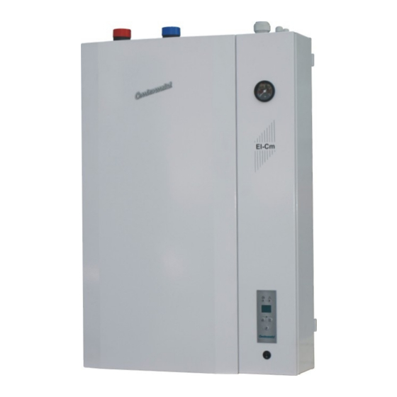
Tehnički podaci Slika 1. - Osnovne dimenzije elektro kotla El-Cm Manometar El-Cm Prednji poklopac (može se skinuti, odvrnuti 4 vijka) Konzola regulacije (može se otvoriti, odvinuti 2 vijka) Digitalna modulirajuća kotlovska regulacija TEHNIKA GRIJANJA Glavna sklopka TEHNIČKI PODACI El-Cm Toplinski učin (kW) Volumen kotl. - Page 3 Osnovni dijelovi Slika 2. - Dijelovi elektro kotla El-Cm Uvodnica za sobni termostat i cirk. pumpu Regulacijska kutija Uvodnica za priključno napajanje Povratni vod Polazni vod Mikroprekidač Nosač kotla Sigurnosni termostat Presostat Sonda za manometar Sonda za ticala Kotao Električni grijač Toplinska izolacija Nosač...
- Page 4 Preporučamo Vam da slijedite naše upute sa pozornošću, kako bi Vaš kotao El-Cm mogao duže i pravilnije raditi. Tvrtka Centrometal d.o.o. ne preuzima odgovornost za moguće netočnosti u ovoj brošuri, nastale tiskanim greškama ili prepisivanjem, u svakom slučaju pridržava si pravo unositi vlastitim proizvodima one izmjene koje smatra potrebnim i korisnim bez prethodne najave.
- Page 5 Sastavni dijelovi kotla ELEKTRIČNI GRIJAČI El. grijači ugrađeni su sa donje strane kotla, snage ovisne o ukupno potrebnoj maksimalnoj snazi kotla. TERMOIZOLACIJSKI SLOJ Elektro kotao El-Cm izoliran je termoizolacijskim slojem mineralne vune, odgovarajuće gustoće, debljine 30 mm na Al-foliji, koja smanjuje gubitak topline konvekcijom i zračenjem. PUNJENJE/PRAŽNJENJE Na donjoj strani tijela kotla, zabrtvljena je slavina za punjenje/pražnjenje kotla i sistema.
- Page 6 Montaža kotla 4.0. MONTAŽA KOTLA Elektro kotao El-Cm predviđen je za montažu na zid za koju ima na stražnjoj strani predviđene konzole za ovješenje. Za ovješenje se mogu upotrijebiti metalni zidni ulošci (tiple) sa vijkom M10 ili jači plastični zidni ulošci. Kotao mora biti montiran najmanje 0,6 m od poda radi eventualne zamjene el.
- Page 7 Priključenje na instalaciju grijanja 5.0. PRIKLJUČENJE KOTLA El-Cm NA INSTALACIJU GRIJANJA Priključenje na cijevnu instalaciju sustava grijanja i puštanje u pogon kotla, mora se izvesti prema važećim tehničkim normama, od strane stručne osobe, koja preuzima odgovornost. Kod zatvorenog sustava grijanja obavezna je ugradnja atestiranog sigurnosnog ventila s tlakom otvaranja 0,25 MPa (2,5 bar-a) i membranske ekspanzijske posude.
- Page 8 Elektro priključak, regulacija 6.0. ELEKTRO PRIKLJUČAK Sve elektro radove treba izvesti prema važećim propisima i od strane ovlaštene osobe. Kompletna elektro instalacija kotla izvedena je tvornički. Sva dodatna spajanja (napajanje kotla, cirkulacijska pumpa grijanja, sobni termostat) vrše se na rednoj stezaljci kotla. Cirkulacijsku pumpu grijanja spojiti na rednu stezaljku na regulaciji na stezaljke br.
-
Page 9: Električna Shema
Električna shema Shema 1. - El. shema elektro kotla El-Cm 30 - 51 kW (3-fazni priključak) REGULACIJSKA PLOČA Pumpa Redna stezaljka EG EG EG EG EG EG EG EG EG EG EG P - glavni prekidač K - kontaktor 1 LEGENDA: LED-DISPLAY ST - sigurnosni termostat... - Page 10 El. pločica Shema 2. - Prikaz el. pločice elektrokotla Priključne redne stezaljke Tehničko uputstvo El-Cm...
- Page 11 Regulacija, zamjena elektrogrijača 7.0. TEHNIČKI PODACI REGULACIJE - priključni napon:................400V / 50Hz - način upravljanja grijača:..........modulirajuća regulacija - potrošnja elektronike:................max 10 VA - područje regulacije:.................30-90°C 8.0. ZAMJENA ELEKTRO GRIJAČA Prije skidanja prednjeg poklopca potrebno je prekinuti dovod električne energije na kotao. Zatim je potrebno skinuti prednji poklopac i donju stranicu oplate (koji su pričvršćeni vijcima).
- Page 12 Regulacija 9.0. REGULACIJA Slika 5. - Digitalna regulacija Greška (LED-dioda) Pumpa (LED-dioda) Display Rad elektrogrijača (LED-dioda) Funkcijske tipke Regulacija kotla El-Cm radi tako da mjeri temperaturu i uspoređuje je sa zadanom (željenom) temperaturom, te na temelju toga traži optimalan raspored snage za zagrijavanje sistema na željenu temperaturu.
- Page 13 Regulacija Primjer: kotao El-Cm 30 kW Uvijek nakon uključivanja kotao se zagrijava najvećom snagom dok ne postigne željenu temperaturu. Kad je postignuta željena temperatura regulator regulira rad kotla raspoređujući snagu uključenih grijača ovisno o veličini temperature za koju treba zagrijati kotao i to u koracima 30 kW, 22,5 kW, 15 kW, 7,5 kW (MOD1).
- Page 14 Greške GREŠKE Moguće su različite greške do kojih može doći tijekom rada. Ako na display-u piše X (X označava broj 0-5), znači da je došlo do greške pri radu regulatora, a broj označava uzrok greške: 0 - previsoka je temperatura na senzoru, >90°C. 1 - pogrešna vrijednost na senzoru - vrijednost izvan mjernog područja ili je senzor temperature pogrešno okrenut.
- Page 15 Tablica otpora osjetnika TABLICA OTPORA NTC 5k/25°C OSJETNIKA (mjerno područje - 20 to + 130 °C) Temperatura (°C) Otpor (Ω) 48.535 36.465 27.665 21.158 16.325 12.694 9.950 7.854 6.245 5.000 4.028 3.266 2.663 2.184 1.801 1.493 1.244 1.041 740,7 629,0 536,2 458,8 394,3...
-
Page 16: Technical Data
Technical data Picture 1. - Basic technical dimensions of the electrical boiler El-Cm Manometer El-Cm Front cover Console of the regulation Digital modulating regulation Main switch TECHNICAL DATA El-Cm Nom. thermal output (kW) Capacity (lit.) Electric boiler mass (kg) Max. operating press. (bar) Max. - Page 17 Essential parts Picture 2. - Essential parts of the electric boiler El-Cm Wire introducer (pump, room thermostat) Regulation box Wire introducer (power supply) Outlet Inlet Microswitch Boiler porter Safety thermostat Pressure switch Manometer probe Sensor probe Boiler Electric heater Thermal insulation Boiler porter Boiler casing Filling/Draining...
-
Page 18: Boiler Description
Boiler description 1.0. INTRODUCTION Hot water electric boiler El-Cm has a modern design and is constructed out of certified high quality materials by applying most modern robot welding technology, it is certified according to domestic and international norms and is therefore suitable for connection to central heating system installation. -
Page 19: Boiler Parts
Boiler parts OUTLET The outlet tube (6/4”) is marked by the blue coloured sticker and is placed on the upper right side of the electric boiler. It is inserted through the whole length of the electric boiler till its deepest point in order to spread the cooled water inside the electric boilers body and over the electric heater/heaters. - Page 20 Installation of electric boiler 4.0. INSTALLATION OF ELECTRIC BOILER The El-Cm electric boiler is aimed to be hanged on the wall. For the easier setting on the wall, there is a hanging console on its back part which is to be hanged on wall metal dowels of M10 type or even stronger. Electric boiler has to be hanged on the height of min.
- Page 21 Connecting to the central heating system 5.0. CONNECTING THE El-Cm TO THE CENTRAL HEATING SYSTEM Connecting to tube installation of the central heating system and the start-up of the electric boiler has to be executed considering all technical standards and norms, on behalf of the authorized person, who is able to take over the responsibility.
-
Page 22: Electric Connection
Electric connection 6.0. CONNECTION TO THE ELECTRICAL POWER NET All connections to the electrical power net have to be executed in compliance with all norms and standards by an authorized person. The electric boiler is completely prewired. All additional connections (electric boiler supply, heating pump, room thermostat) are aimed to be connected through the ordinaly terminal under the front cover of the electric boiler. -
Page 23: Electric Scheme
Electric scheme Scheme 1. - Electric scheme of the El-Cm 30 - 51 kW (3-phase connection) REGULATION PANEL Connection voltage 3x400V Pump Ordinaly terminal EG EG EG EG EG EG EG EG EG EG EG LEGEND: P - main switch K - contactor 1 LED-DISPLAY ST - safety thermostat... - Page 24 Electric board Scheme 2. - Electric board of the El-Cm boiler Ordinaly terminal Technical manual El-Cm...
- Page 25 Replacement of the el. heaters 7.0. TECHNICAL DATA - tension:.....................400V / 50Hz - el. boiler steering mode:.............modulating regulation - electronic part consumption:...............max. 10 VA - regulation area:..................20-85°C 8.0. REPLACEMENT OF THE ELECTRIC HEATER Before You take off the front cover it is necessary to disconnect the power supply. Then we take off the front cover and lower side of the casing (which are fasten with the screws).
- Page 26 Regulation 9.0. REGULATION Picture 5. - Digital regulation Error (LED-diode) Pump (LED-diode) Display Operation of el. heater (LED-diode) Function button The regulator of the El-Cm measures the temperature and compares it with the set up (desired) temperature. On this basis it searches for the optimal apportionment of the power used for the system heating to the desired temperature. The regulator is switched off/on by means of the room thermostat (by turning off the 230V supply).
- Page 27 Regulation Example: El-Cm 30 kW Always after the start-up the electric boiler is warming up intensively, until the desired temperature level has been reached. When the desired temperature level has been reached, the regulator steers the operation of the electric boiler allocating the power of activated heaters depending to the desired temperature to be reached, step by step, i.e.
- Page 28 Table of resistance of the boiler sensor TABLE OF RESISTANCE OF THE NTC 5k/25°C BOILER SENSOR (measuring field from - 20 to + 130 °C) Temperature (°C) Resistance (Ω) 48.535 36.465 27.665 21.158 16.325 12.694 9.950 7.854 6.245 5.000 4.028 3.266 2.663 2.184...
- Page 29 Errors ERRORS During the operation of the device some errors could appear. If the display shows X (X stays for the number 0-5), it means that there is a regulator operation error. The number shows its reason. 0 - too high temperature on the sensor > 90°C 1 - wrong value on the sensor the value is out of the measuring field (>99°C) or the temperature sensor is wrong...
- Page 30 Centrometal d.o.o. shall not be responsible for possible incorrect data caused by printing errors or error made in transcription and all figures and diagrams are for explanatory purposes only and relevant adjustment have to be made at the spot.
Need help?
Do you have a question about the El-Cm Series and is the answer not in the manual?
Questions and answers