Table of Contents
Advertisement
Quick Links
Centrometal d.o.o. Glavna 12, 40306 Macinec, CROATIA
sales department tel: +385 40 372 640
central tel: +385 40 372 600, fax: +385 40 372 611
www.centrometal.hr
e-mail: servis@centrometal .hr
HEATING TECHNIQUE
HEATING TECHNIQUE
Centrometal d.o.o. - Glavna 12, 40306 Macinec, CROATIA, tel: +385 40 372 600, fax: +385 40 372 611
TECHNICAL MANUAL
for assembling, use and maintenance
of solid fuel firing boiler and its
additional equipment
TUCKS-11/2015
EKO-CKS
Advertisement
Table of Contents

Subscribe to Our Youtube Channel
Related Manuals for Centrometal EKO-CKS


Summary of Contents for Centrometal EKO-CKS
- Page 1 HEATING TECHNIQUE Centrometal d.o.o. - Glavna 12, 40306 Macinec, CROATIA, tel: +385 40 372 600, fax: +385 40 372 611 TECHNICAL MANUAL for assembling, use and maintenance of solid fuel firing boiler and its additional equipment Centrometal d.o.o. Glavna 12, 40306 Macinec, CROATIA...
-
Page 2: Technical Data
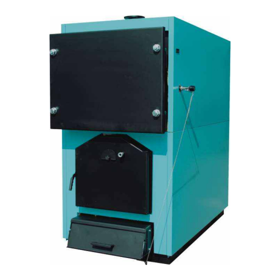
EKO - CKS EKO - CKS EKO - CKS EKO - CKS TYPE 1000 1000 1000 1150 1600 1600 2100 2100 2100 1280 1280 1705 1705 1705 1965 2000 2000 2350 2350 1006 1006 1356 1356 Technical manual EKO-CKS Technical manual EKO-CKS... - Page 3 Secondary air door Upper boiler door Inlet Visual control opening Filling/Draining Primary air door/opening for Outlet cleaning Opening for draught regulator Underpressure regulator lid (with cyclone - watertight sealed) Side air opening SPLV Safety inlet line Technical manual EKO-CKS Technical manual EKO-CKS...
-
Page 4: Description Of The Boiler
Additional firing of the boiler in the heating room - (see plan for the boiler casing EKO-CKS on the regulation can be achieved through the secondary air door which is situated on the page 13). - Page 5 1.1. DELIVERY PACKAGE In order to obtain a regular and safe operation of the EKO-CKS boiler connected with the cyclone CC and the fan there is a need to install the boiler regulation. The - Boiler's body with the door...
-
Page 6: Technical Manual
Every heating room has to have an primary air opening dimensioned according to the boiler's capacity. The opening has to be protected by a net. A=6,02 Q opening surface in cm˛ rated thermal output in kW Technical manual EKO-CKS Technical manual EKO-CKS... - Page 7 Opening for cleaning BOILER EKO-CKS min. 300 mm max. 700 mm Image 2. Connection of the EKO-CKS to the chimney through the cyclone CC and the fan drive Temperature at rated thermal output Thermal insulation has to be min. 160°C-180°C necessary...
- Page 8 13.7. THE ROTOR AND THE FAN'S HOUSING Image 3. Dimensioning the chimney for EKO-CKS boilers (Tdpl=250°C) - boiler connection directly to the chimney (without cyclone and fan drive). Both parts are subjected to the wear and tear. The main reason is dust, i.e. the acid mixed with the medium inside the tubes, steam and gases.
- Page 9 Image 5. (tightness, wear and tear). In case the spare parts are needed, they have to be cleaned previously. Technical manual EKO-CKS Technical manual EKO-CKS...
- Page 10 Connection scheme Additional equipment-cyclone and fan 12.0. CYCLONE CC Image 4. General connection plan of the EKO-CKS boiler to the open system The cyclone CC produced by Centrometal is used to filter flue gases. 12.1. CONNECTING THE CYCLONE CC The cyclone CC has to be connected to the chimney behind the boiler. A general connection plan is shown on the Image 2, page 7.
- Page 11 Technical data for cyclone CC Connection scheme Cyclone CC - technical data Image 5. General connection plan of the EKO-CKS boiler to the heating system ..Connection to the cyclone and flue exhaust installation Connection to the boiler BOILER Box for cleaning the cyclone...
-
Page 12: Filling The System
(see page 3) there is an output. It is connected by an 1/2“ inside thread to which a flexible plastic/gum pipe can be connected which is draining the condensate into the plastic pot, or simply out of the boiler. CYCLONE CC AND THE FAN Technical manual EKO-CKS Technical manual EKO-CKS... - Page 13 Notes Assembling order for the casing Image 6. Assembling order for the casing of EKO-CKS boiler Detail X lower casing porter Detail Y upper casing porter Detail Z (4.2x16) (fi 12x4.2) factory mounted (4.2x32) (3.9x9.5) Insert the lower lateral part of the insulation (1) into the slit D in order it fits into the lower boiler casing porter (see detail Y), in the same time put the lower part of the casing into the lower slit.
-
Page 14: Cleaning And Maintaining
- secondary air flow is set (can also be closed) cause corrosion of the entire central heating system as well of the boiler' interior. - training the person in charge of the boiler room, training protocol signed by the trained person. Technical manual EKO-CKS Technical manual EKO-CKS...
Need help?
Do you have a question about the EKO-CKS and is the answer not in the manual?
Questions and answers