Table of Contents
Advertisement
Quick Links
Advertisement
Table of Contents

Related Manuals for RCF MXR 4500


Summary of Contents for RCF MXR 4500
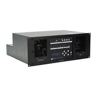
- Page 1 OWNER’S MANUAL MANUALE UTENTE MXR 4500 RACK MOUNT AMPLIFIED MASTER UNIT...
-
Page 3: Table Of Contents
CONTENTS CONTENTS .................................. 3 SAFETY PRECAUTIONS AND GENERAL INFORMATION ....................5 DXT 3000 SYSTEM DESCRIPTION ..........................9 UNPACKING, INSTALLATION AND COOLING......................11 CONFIGRATION EXAMPLES ............................12 MAIN BOARD ................................13 MESSAGES SD CARD BOARD ............................. 21 INTERLINK BOARD ..............................23 SPARE AMPLIFIER SETTING ............................ - Page 4 CAUTION RISK OF ELECTRIC SHOCK ATTENTION DO NOT OPEN CAUTION WARNING: SHOCK HAZARD – DO NOT OPEN ATTENTION: RISQUE D’ELÉCTROCUTION - NE PAS OUVRIR WARNING: TO REDUCE THE RISK OF FIRE OR ELECTRIC SHOCK DO NOT EXPOSE THIS EQUIPMENT TO RAIN OR MOISTURE ATTENTION: NE PAS EXPOSER CE MATÉRIEL À...
-
Page 5: Safety Precautions And General Information
RCF S.p.A. will not assume any responsibility for the incorrect installation and / or use of this product. - Page 6 Also check the suitability of the support surface to which the product is anchored (wall, ceiling, structure, etc.), and the components used for attachment (screw anchors, screws, brackets not supplied by RCF etc.), which must guarantee the security of the system / installation over time, also considering, for example, the mechanical vibrations normally generated by transducers.
- Page 7 Do not use solvents, alcohol, benzene or other volatile substances for cleaning the external parts of this product. IMPORTANT NOTES To prevent the occurrence of noise on line signal cables, use screened cables only and avoid putting them close to: Equipment that produces high-intensity electromagnetic fields Power cables Loudspeaker lines...
- Page 8 Modifications: Any modifications made to this device that are not approved by RCF may void the authority granted to the user by the FCC to operate this equipment. RCF S.p.A. reserves the right to make changes without prior notice to rectify any errors and / or...
-
Page 9: Dxt 3000 System Description
(UNI ISO 7240-19). MXR 4500 is the main unit with a metallic enclosure for rack-mounting into a 19” rack cabinet (4 units), and it has all necessary components inside for the system operating, included a digital sound processor (DSP) that allows a proper equalization. - Page 10 MXR 4500 main unit has a backup power supply that meets the EN 54-4 standard, with recharging unit and check of batteries (18 Ah). To ensure a full system efficiency, it is strongly advised to check batteries every two years and replace them if necessary.
-
Page 11: Unpacking, Installation And Cooling
MXR 4500 master unit shall be installed into a 19” rack cabinet (4 units) leaving 1 empty unit between other units, in order to guarantee the air flow necessary for an effective thermal dissipation. -
Page 12: Configration Examples
(with automatic change-over). On request, the main unit can be delivered with four (MXR 4500/4) / six (MXR 4500/6) built-in power amplifiers. The overall power is always 500 W and it can be freely shared among the four / six zones (within the limit of max. 250 W per zone, power that corresponds to either a 40 Ω... -
Page 13: Main Board
MAIN BOARD The main board is the system control unit and linked to all the other boards. It can be accessed by loosening the screws on the back of the unit and then removing the cover [B]. - Page 14 Once removed the cover, system’s connections and settings will be available. SYSTEM’S CONNECTORS Input for monitored paging microphones with emergency purposes (e.g. BM 3804). DESCRIPTION BM 3804 CABLE – WIRE COLOUR Audio signal (+, hot) Orange/White (RJ pin 1) Audio signal (–, cold) Orange (RJ pin 2) Serial port RS 485 A (+) Brown/White (RJ pin 7)
- Page 15 Correspondence of wires between CAT 6 and CJ 428CAT cables: DESCRIPTION CAT 6 WIRE COLOUR CJ 428CAT WIRE COLOUR Audio signal (+, hot) Orange/White Audio signal (–, cold) Orange Blue Power supply Green/White Yellow Ground Blue Brown Ground Blue/White Green Ground Green Grey...
- Page 16 ANY EVAC OUT logic output (relay normally open dry contact), activated (relay contact shorted) when evacuation is in progress. (*) GENERAL FAULT logic output: relay normally closed dry contact (when MXR 4500 is turned on) that opens when either a fault is detected or MXR 4500 is off.
- Page 17 Logic input for the external power supply fault. The two contacts (PSU and G) need to be kept open when the external power supply is normal. Shorting the two contacts entails the fault indication. Logic input to toggle the day / night operating mode: -- ‘DAY’, the two contacts (N/D and G) are open -- ‘NIGHT’, the two contacts (N/D and G) are shorted.
- Page 18 (default setting): the audio signal of the music source linked to the BGM IN input is only available for the MXR 4500 main unit to which it is connected. INTERLINK (only with the optional INTERLINK board): the audio signal of the...
- Page 19 BGM LEVEL jumper: BGM IN audio input gain setting. [16] JUMPER SETTING INPUT GAIN not inserted no gain pins 1 – 2 + 3 dB pins 2 – 3 + 6 dB DIP-SWITCH DIP-SWITCH SETTING FUNCTION BM 3804 paging microphones linked to the INTERLINK board (when available).
- Page 20 SINGLE – EVACUATION / PAGING mode: each logic output (when [11] activated) indicates the playback of the evacuation message or paging 1: ON, 2: OFF in its zone (A = zone 1, B = zone 2, C = zone 3, D = zone 4, E = zone 5, F = zone 6).
-
Page 21: Messages Sd Card Board
MESSAGES SD CARD BOARD Remove the screw marked in RED to access the SD CARD and manage the messages. The message player board is directly fitted to the main board. Messages are stored to an SD CARD, which can also be used to update the firmware. - Page 22 Messages shall be named as follows: EMERGENCY MESSAGES a0, a1, a2: ‘Alert’ messages (max. 3) c0, c1, c2: ‘All clear’ messages (max. 3) e0, e1, e2, e3: ‘Evacuation’ messages (max. 4) h0, h1, h2: chime sent before an announcement SYSTEM TEST pre-test (main menu) test (main menu) end-test (main menu)
-
Page 23: Interlink Board
MAXIMUM NUMBER OF UNITS IE 3008 allows connecting up to 8 units MXR 4500 in a MASTER/SLAVE configuration. The first unit will be the MASTER, and the others will be SLAVEs. A fixed ID will identify each unit, and can be set through a hardware DIP SWITCH placed on IE 3008. - Page 24 MAXIMUM NUMBER OF CONSOLE EXTENSIONS BE 3806 Up to 8 BE 3806 can be connected to each BM 3804 in the chain. Each extension manages one MXR unit, and buttons are statically assigned to one zone only. SYSTEM’S SPECIFICATIONS The maximum distance allowed between MXR MASTER and last MXR SLAVE is 800m. The maximum distance allowed between MXR MASTER and the last BM 3804 is 800m.
- Page 25 ID SET DIP-SWITCH: it allows to set the ID number of each unit, and to set the MASTER. [27] ID 0 ID 1 ID 2 MASTER / SLAVE MASTER LAST SLAVE ID SLAVE 1 SLAVE 2 SLAVE 3 SLAVE 4 SLAVE 5 SLAVE 6 SLAVE 7...
-
Page 26: Spare Amplifier Setting
SPARE AMPLIFIER SETTING WARNING: before proceeding with the setting, make sure that the unit is switched off and disconnected from the primary power source and from the batteries. To set the spare amplifier functionality remove the metal flap on the lower left side of the unit’s front panel. Behind the flap set the jumpers as shown in the pictures below. -
Page 27: Batteries Connection
BATTERIES CONNECTION System batteries shall be placed on a stable shelf inside the rack (e.g. RCF BH 1042). Each unit requires 4 batteries (12 V – 18 Ah), to be connected together using the dedicated cables, included in the package. - Page 28 Connector E shall be linked to the 2 meters long extension cord provided in the package, and then to the connector placed on the unit’s rear panel.
-
Page 29: Loudspeakers Connection
LOUDSPEAKERS CONNECTION Loudspeakers lines connectors (euroblock) are placed in the upper right side of the unit’s rear panel. For loudspeakers connection refer to instructions shown on the cover label. - Page 30 NOTES ABOUT CONSTANT VOLTAGE SYSTEMS • The loudspeaker input voltage (Vd) shall correspond to the amplifier output voltage (Va). • The sum of nominal power values (Pd x n) of all loudspeakers connected to the line shall not exceed the amplifier power (Pa).
- Page 31 The amplifier board has two outputs (two zones) and the max. overall total power is 500 W (max. 250 W per each zone). The zone number can be increased to 4 or 6 (by adding one or two amplifier boards), but the max. total output power is always 500 W.
- Page 32 “The recommended tolerance value is the highest of the available options, but lower than the weight of the smallest percentage change in impedance, usually due to the disconnection of the speaker having the highest impedance and installed at the end of a line branch.” An example: a line has a total impedance 80 Ω...
- Page 33 NOTE : the line impedance (Zline) here is considered at the frequency of 20 Hz (which is not equal to the one measured by an impedance meter at 1 kHz)! In case of a single line having a particularly low impedance load or lines including horn speakers (open circuits at 20 Hz), it will be necessary to add more EOL in parallel.
-
Page 34: Fire Alarm System Monitoring
FIRE ALARM SYSTEM MONITORING SINGLE LINE MONITORING - GENERAL ALARM SEPARATE MONITORING OF EACH LOGIC INPUT - ZONE ALARM... -
Page 35: Start Up Procedure
2. Make sure the main board dip-switch no. 6 (SWITCH ON/OFF) [17] is set to OFF. 3. Connect the batteries. 4. Connect the MXR 4500 main unit to the mains power supply. 5. Set the main board dip-switch no. 6 (SWITCH ON/OFF) [17] to ON. -
Page 36: Front Panel Board
The access to the other menus is regulated by password levels. PASSWORD CHANGE MXR 4500 has 4 access levels, which correspond to operating rights, as required by EN 54-16:2008. The first level (0) does not require any password. About the other levels, their initial default passwords are: •... -
Page 37: Front Panel
FRONT PANEL Four key-cursor ( : up, : down, : left, : right) OK button: press to select. ESC button: press to quit the displayed menu. SILENCE INTERNAL SOUNDER button: press to mute the internal sounder (fault acknowledge). FAULT LEDs Yellow One or more faults have been detected. - Page 38 SYSTEM CONDITION LEDs: The evacuation message is currently played. [11] ALARM Yellow The alert message is currently played. [12] ALERT Green Either the mains (230 – 115 V ac) or the 24 V dc power supply is present. [13] POWER PRESENT MP3 AUDIO PLAYER SD card port (“Secure Digital”).
-
Page 39: Parameter List
PARAMETER LIST LEVEL 1 LEVEL 2 LEVEL 3 DESCRIPTION INFO FIRMWARE VER Microprocessor current firmware release. Current firmware release of the AMP VER microprocessor for line monitoring. DSP VER DSP current firmware release. ZONES NUMBER System zone number. ACTIVE EVC/ALRT Zones with evacuation or alert in progress. - Page 40 LEVEL 1 LEVEL 2 LEVEL 3 DESCRIPTION AUDIO SET Audio setting of pre-recorded MESSAGES messages. INPUT LEVEL Input level (– 40 ÷ + 6 dBu). EQUALIZER 2-band equalizer (HI/LO) (–10 ÷ + 12 dB). ASSIGN (for each It assigns the message playback zone) to the selected zones.
- Page 41 LEVEL 1 LEVEL 2 LEVEL 3 DESCRIPTION AUDIO SET Selected zone audio settings. ZONE n (for each zone; n: selected zone) LEVEL Output level (NOTE: to be used only for temporary changes, as it is overwritten by the parameter EVENT LEVEL). EQUALIZER 2-band equalizer (HI/LO) (–10 ÷...
- Page 42 LEVEL 1 LEVEL 2 LEVEL 3 DESCRIPTION FAULTS FAULT_LINE6_IMP line 6 impedance FAULT_LINE_EARTHED line with earth leakage FAULT_SPARE_ON spare amplifier LEVEL 1 LEVEL 2 LEVEL 3 DESCRIPTION UTILITY LEDS BUZZER TEST LED and buzzer test. Automatic quit from menus after ESC TIMEOUT a certain time [ON/OFF].
- Page 43 LEVEL 1 LEVEL 2 LEVEL 3 DESCRIPTION MESSAGES Main menu user messages USER MESSAGES PLAY PRE-TEST It plays the pre-test message. PLAY TEST It plays the test message. PLAY END-TEST It plays the end-test message. STOP It stops the current message. LOGIN (access to the security levels by entering the 3-digit password) LOGOUT (quit and return to the lowest security level ‘0’) LEVEL 1...
- Page 44 LEVEL 1 LEVEL 2 LEVEL 3 DESCRIPTION SERVICE CHIME MESSAGE Preferred chime selection among no.1, 2, 3. EVAC GPI N. S. GPI normal status selection: OPEN (default) or CLOSED. EVAC GPO N. S. GPO normal status selection: OPEN (default) or CLOSED. RESET GPI N.
-
Page 45: Dimensions
DIMENSIONS... -
Page 46: Specifications
SPECIFICATIONS System specifications Number of zones managed 6 (MXR 4500/6) / 4 (MXR 4500/4) / 2 (MXR 4500/2) Built-in power amplifier Spare amplifier automatic change-over Max number of consoles Number of console buses Number of simultaneous emergency audio channels Max number of units connectable... - Page 47 Controls Configuration DIP switch, Front panel Chime tone Protections Cooling Convection Short circuit Thermal Fuses VHF (Very High Frequencies) Audio sources USB pen drives SD card Power requirement Operating voltage 220-240/115 V~ 50/60Hz Voltage selection Internal DC power DC power value 48 V Power consumption 700 W...
- Page 48 0068 RCF S.p.A. - Via Raffaello Sanzio 13, 42124 Reggio Emilia, ITALY 0068-CPR-007/2015 EN 54-16:2008 Voice alarm control and indicating equipment for fire detection and fire alarm systems for buildings EN 54-4:1997 + A1:2002 + A2:2006 Power supply equipment for fire detection and fire alarm systems...
- Page 52 RCF S.p.A. Via Raffaello Sanzio, 13 - 42124 Reggio Emilia – Italy 10307793 A EN Tel +39 0522 274 411 - Fax +39 0522 232 428 - e-mail: info@rcf.it - www.rcf.it...
Need help?
Do you have a question about the MXR 4500 and is the answer not in the manual?
Questions and answers