
Related Manuals for RCF ED600


Summary of Contents for RCF ED600
- Page 1 ����� ������ �� ������ � �������� ������� ������ ����� ����������� � ������������ ��� ��������� ������ � ������� ��������������� � �����...
- Page 3 L’installazione e l’utilizzo errati del prodotto esimono la RCF S.p.A. da ogni responsabilità. ATTENZIONE: Per prevenire i rischi di fiamme o scosse elettriche, non esporre mai questo prodotto alla pioggia o all’umidità...
-
Page 4: Note Importanti
Verificare inoltre l’idoneità del supporto (parete, soffitto, struttura ecc., al quale è ancorato il prodotto) e dei componenti utilizzati per il fissaggio (tasselli, viti, staffe non fornite da RCF ecc.) che devono garantire la sicurezza dell’impianto / installazione nel tempo, anche considerando, ad esempio, vibrazioni meccaniche normalmente generate da un trasduttore. -
Page 5: Comandi E Funzioni
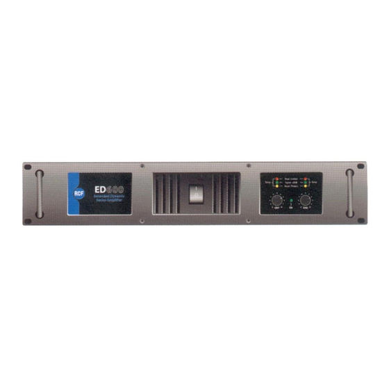
RCF S.p.A. Vi ringrazia per l’acquisto di questo prodotto, realizzato in modo da garantirne l’affidabilità e prestazioni elevate. COMANDI E FUNZIONI PANNELLO FRONTALE 1. INTERRUTTORE GENERALE Accende e spegne l’apparecchio interrompendo entrambe le fasi. 2. INDICATORE DI ACCENSIONE LED verde indicante il corretto funzionamento. -
Page 6: Pannello Posteriore
PANNELLO POSTERIORE 1. INGRESSI BILANCIATI XLR Ingressi audio bilanciati (per ciascun canale) con connettori XLR. Nel caso si usino segnali sbilanciati, occorre collegare insieme i pin nr.1 (massa) e nr.3 ed utilizzare i pin nr.2 per i segnali. Per le configurazioni MONO e BRIDGE utilizzare solo l’ingresso CH1. 2. - Page 7 PROTEZIONI PROTEZIONI TERMICHE Nel caso si verifichi una situazione di surriscaldamento dell’amplificatore (temperatura >90°C), questo andrà in protezione ponendo in “mute” il segnale audio in ingresso fino al raggiungimento delle condizioni di normale funzionamento. Tale intervento è segnalato con l’accensione contemporanea dei LED (rosso PEAK / LIMITER - giallo MUTE / PROT) posti sul frontale dell’apparecchio che riportano l’indicazione TEMP.
-
Page 8: Installazione
INSTALLAZIONE CONFIGURAZIONE STEREO Porre il selettore MODE (posto sul retro dell’amplificatore) sulla posizione STEREO, utilizzando entrambi gli ingressi audio ed i relativi controlli di volume. L’impedenza dei diffusori NON deve essere inferiore a 4 Ω per ciascun canale. CONFIGURAZIONE MONO Porre il selettore MODE sulla posizione MONO ed utilizzare solo l’ingresso audio CH1. - Page 9 NOTE PER L’INSTALLAZIONE Gli amplificatori della serie ED sono disegnati per essere posti in rack / flight-cases 19” (altezza: 2 unità). Se l’installazione è effettuata all’interno di un rack, è consigliabile utilizzare anche i fissaggi predisposti sul retro dell’amplificatore per evitare che il pannello frontale debba sopportare tutto il peso dell’apparecchio.
-
Page 10: Risoluzione Dei Problemi
RISOLUZIONE DEI PROBLEMI In caso di problemi o cattivo funzionamento, consultare la seguente lista prima di contattare un centro assistenza autorizzato. L’APPARECCHIO NON SI ACCENDE • Assicurarsi della corretta posizione dell’interruttore d’accensione. • Controllare la corretta connessione alla rete d’alimentazione. •... -
Page 11: Dati Tecnici
DATI TECNICI ED 600 ED 1100 POTENZA D’USCITA [RMS] STEREO 4 Ω - 2 x 300 W 4 Ω - 2 x 550 W 8 Ω - 2 x 180 W 8 Ω - 2 x 265 W PONTE 8 Ω - 1 x 600 W 8 Ω... -
Page 12: Schema A Blocchi
SCHEMA A BLOCCHI... -
Page 13: Important Notes
RCF S.p.A. will not assume any responsibility for the incorrect installation and / or use of this product. -
Page 14: Operating Precautions
(screw anchors, screws, brackets not supplied by RCF etc.), which must guarantee the security of the system / installation over time, also considering, for example, the mechanical vibrations normally generated by transducers. -
Page 15: Controls And Functions
RCF S.p.A. would like to thank you for having purchased this product, which has been designed to guarantee reliability and high performance. CONTROLS AND FUNCTIONS FRONT PANEL 1. MASTER SWITCH It switches the amplifier on / off (interrupting both the phases). - Page 16 REAR PANEL 1. BALANCED XLR INPUTS Balanced audio inputs (for each channel) with XLR connectors. When unbalanced signals are used, pins 1 (gnd) and pins 3 are to be connected together; use [pins 2] for the signals. In MONO and BRIDGE modes, use the input CH1 only. 2.
-
Page 17: Short Circuit Protection
PROTECTION DEVICES THERMAL PROTECTION When the amplifier becomes overheated (temperature >90°C), this protection device puts the audio signal in mute status until normal operating conditions have been restored. This intervention is signalled by the simultaneous lighting of the LEDs (red PEAK / LIMITER - yellow MUTE / PROT) located on the front of the amplifier that give the TEMP indication. -
Page 18: Installation
INSTALLATION STEREO MODE Set the MODE selector to STEREO. Use both audio inputs and the respective volume controls. The loudspeaker impedance must NOT be less than 4 Ω per channel. MONO MODE Set the MODE selector to MONO. Use the CH1 audio input only. The CH1 volume control adjusts the level on both channels. -
Page 19: Notes For Installation
NOTES FOR INSTALLATION The ED series amplifiers are designed to be housed in 19” racks / flight-cases (height: 2 units). If installation is made inside a rack enclosure, we recommend you to use the attachment fittings on the back of the amplifier, so the front panel does not have to support the entire unit weight. Make sure there is sufficient ventilation for the amplifier to be cooled correctly. -
Page 20: Troubleshooting
TROUBLE-SHOOTING In the event of problems or poor operation, consult the following checklist before contacting your authorised service centre. THE AMPLIFIER DOES NOT SWITCH ON • Make sure the power switch is in the right position. • Make sure the mains connection is made properly. •... -
Page 21: Technical Data
TECHNICAL DATA ED 600 ED 1100 OUTPUT POWER [RMS] STEREO 4 Ω - 2 x 300 W 4 Ω - 2 x 550 W 8 Ω - 2 x 180 W 8 Ω - 2 x 265 W BRIDGE 8 Ω - 1 x 600 W 8 Ω... -
Page 22: Block Diagram
BLOCK DIAGRAM... - Page 24 ��� ��� ��� ���������� �� � ����� ��������� ������ ������ � ����� ����� ��� ���� ������ ���� ��� ���� ������ ������� ����������� ���������� ������ �������� ������ ��� ���������� ��� ������ �������� ��� ����� �� ���� ������������� ������� ����� ������� ����� ��������� ������ �� ���������� ����������...
Need help?
Do you have a question about the ED600 and is the answer not in the manual?
Questions and answers