
Subscribe to Our Youtube Channel
Related Manuals for RCF QPS 9600


Summary of Contents for RCF QPS 9600
- Page 1 OWNER MANUAL MANUALE D’USO QPS 9600 - FOUR-CHANNEL POWER AMPLIFIER - AMPLIFICATORE CON QUATTRO CANALI...
-
Page 3: Table Of Contents
INDEX INDICE ENGLISH SAFETY PRECAUTIONS DESCRIPTION UNPACKING AND INSTALLATION FRONT PANEL REAR PANEL OPERATION MODES SPEAKON CONNECTOR WIRING COOLING REQUIREMENTS SPECIFICATIONS ITALIANO AVVERTENZE PER LA SICUREZZA DESCRIZIONE DISIMBALLO ED INSTALLAZIONE PANNELLO FRONTALE PANNELLO POSTERIORE MODI DI FUNZIONAMENTO CABLAGGIO DEI CONNETTORI SPEAKON VENTILAZIONE DATI TECNICI... -
Page 4: Safety Precautions
The manual is to be considered an integral part of this product and must accompany it when it changes ownership as a reference for correct installation and use as well as for the safety precautions. RCF S.p.A. will not assume any responsibility for the incorrect installation and / or use of this product. WARNING WARNING: To prevent the risk of fire or electric shock, never expose this product to rain or humidity. - Page 5 Also check the suitability of the support surface to which the product is anchored (wall, ceiling, structure, etc.), and the components used for attachment (screw anchors, screws, brackets not supplied by RCF etc.), which must guarantee the security of the system / installation over time, also considering, for example, the mechanical vibrations normally generated by transducers.
-
Page 6: Description
Its nominal output power is 2400 W RMS @ 2 Ω per each of the four channels (2 x 4800 W RMS bridged @ 4 Ω). Thanks to its high efficiency heat sinks and variable speed DC fans, the QPS 9600 can withstand the hardest heat conditions ensuring great reliability. -
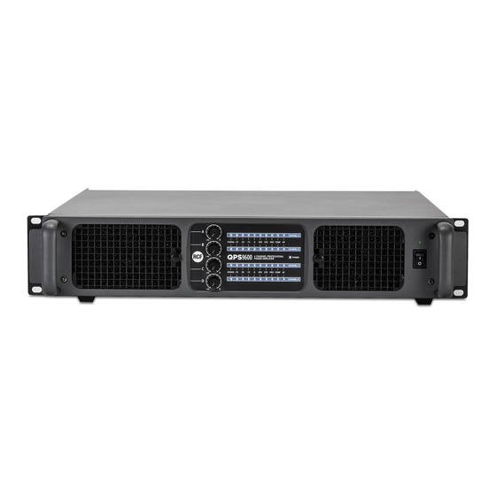
Page 7: Front Panel
FRONT PANEL POWER switch with LED Push to turn on (I) / off (O) the amplifier. Its LED is lit when the amplifier is turned on. Before switching the amplifier on, check all cables and turn fully counterclockwise all the four channel level controls POWER LED When lit, the amplifier is switched on. -
Page 8: Rear Panel
REAR PANEL SPEAKER OUTPUTS C(+D) A(+B) PUSH PUSH PUSH PUSH BRIDGE BRIDGE + 1+ + 1+ – 2– – 2– CH D+ CH C+ CH D+ CH B+ CH A+ CH B+ 1– CH D– 1– CH C– 2– CH D– 1–... - Page 9 CHANNEL D SPEAKER OUTPUT Channel D output to speakers (SPEAKON connector). Do not connect this output if the channels C and D are bridged. See both ‘Operation modes’ and ‘SPEAKON connector wiring’ manual sections. CHANNEL A MODE SWITCH (internal software limiter) If the MODE SWITCH is set to SOFT, the internal software limiter is enabled on the CHANNEL A (together with the VPK hardware voltage peak limiter).
- Page 10 BRIDGE A+B switch Important: make sure the amplifier is turned off before setting this switch. If set to ON, channels A and B are bridged (the respective LED lights up). Leave it on OFF for normal 2-channel operation. See the ‘Operation modes’ manual section. BRIDGE C+D switch Important: make sure the amplifier is turned off before setting this switch.
-
Page 11: Operation Modes
OPERATION MODES FOUR INDIPENDENT CHANNELS Make sure the amplifier is switched off before setting: - the BRIDGE A+B switch to OFF - the BRIDGE C+D switch to OFF - the switch to FOUR INDEPENDENT CHANNELS. All the four channels are completely independent and each front panel level control affects its respective speaker output. - Page 12 A BRIDGED PAIR AND TWO INDIPENDENT CHANNELS Make sure the amplifier is switched off before setting: - the BRIDGE A+B switch to ON - the BRIDGE C+D switch to OFF - the switch to FOUR INDEPENDENT CHANNELS. CHANNELS A AND B: these are bridged and work with the same input signal (channel A input).
- Page 13 SPEAKER OUTPUTS C(+D) A(+B) PUSH PUSH PUSH PUSH BRIDGE BRIDGE + 1+ + 1+ – 2– – 2– CH D+ CH C+ CH D+ CH B+ CH A+ CH B+ 1– CH D– 1– CH B– 1– CH C– 2– CH D–...
-
Page 14: Speakon Connector Wiring
ONLY) COOLING REQUIREMENTS QPS 9600 has a forced air cooling system to maintain a low operating temperature. Make sure there is enough space in the front (and all around) of all amplifiers. If amplifiers are rack-mounted, do not use doors or covers on the front and the rear of rack... -
Page 15: Specifications
SPECIFICATIONS 4 x 1300 W @ 8 Ω RATED OUTPUT POWER (single channels) 4 x 2200 W @ 4 Ω 4 x 2400 W @ 2 Ω 2 x 4400 W @ 8 Ω RATED OUTPUT POWER (bridged outputs) 2 x 4800 W @ 4 Ω Frequency response 20 Hz ÷... -
Page 16: Avvertenze Per La Sicurezza
L’installazione e l’utilizzo errati del prodotto esimono la RCF S.p.A. da ogni responsabilità. ATTENZIONE: per prevenire i rischi di fiamme o scosse elettriche, non esporre mai questo ATTENZIONE prodotto alla pioggia o all’umidità;... - Page 17 Verificare inoltre l’idoneità del supporto (parete, soffitto, struttura ecc., al quale è ancorato il prodotto) e dei componenti utilizzati per il fissaggio (tasselli, viti, staffe non fornite da RCF ecc.) che devono garantire la sicurezza dell’impianto / installazione nel tempo, anche considerando, ad esempio, vibrazioni meccaniche normalmente generate da un trasduttore.
-
Page 18: Descrizione
RCF S.P.A. VI RINGRAZIA PER L’ACQUISTO DI QUESTO PRODOTTO, REALIZZATO IN MODO DA GARANTIRNE L’AFFIDABILITÀ E PRESTAZIONI ELEVATE. DESCRIZIONE QPS 9600 è un amplificatore (finale di potenza con quattro canali indipendenti), di dimensioni compatte (2 unità rack 19”) e leggero, per uso professionale (es. tour) e sistemi installati. -
Page 19: Pannello Frontale
PANNELLO FRONTALE Interruttore principale dell'amplificatore con LED. Premere per accendere (I) o spegnere (O) l'amplificatore. Il LED si illumina quando l'amplificatore è acceso. Prima di accendere l'amplificatore, controllare tutte le connessioni e ruotare completamente in senso antiorario i controlli di livello di tutti i quattro canali. -
Page 20: Pannello Posteriore
PANNELLO POSTERIORE SPEAKER OUTPUTS C(+D) A(+B) PUSH PUSH PUSH PUSH BRIDGE BRIDGE + 1+ + 1+ – 2– – 2– CH D+ CH C+ CH D+ CH B+ CH A+ CH B+ 1– CH D– 1– CH C– 2– CH D– 1–... - Page 21 USCITA AMPLIFICATA CHANNEL D Uscita amplificata del canale D per i diffusori acustici (connettore SPEAKON). Non collegare questa uscita se i canali C e D sono messi “a ponte”. Vedere le sezioni del manuale “Modi di funzionamento” e “Cablaggio dei connettori SPEAKON”.
- Page 22 Selettore BRIDGE A+B Importante: assicurarsi che l'amplificatore sia spento prima di effettuare la selezione. Se impostato su ON, i canali A e B sono messi “a ponte” (il rispettivo LED si illumina). Lasciarlo su OFF per il funzionamento separato dei due canali. Vedere la sezione del manuale “Modi di funzionamento”.
-
Page 23: Modi Di Funzionamento
MODI DI FUNZIONAMENTO QUATTRO CANALI INDIPENDENTI Assicurarsi che l'amplificatore sia spento prima di impostare: - il selettore BRIDGE A+B su OFF - il selettore BRIDGE C+D su OFF - il selettore su FOUR INDEPENDENT CHANNELS (rilasciato). Tutti i quattro canali sono completamente indipendenti ed ogni controllo di livello (sul pannello frontale) agisce (solo) sulla rispettiva uscita altoparlanti. - Page 24 UNA COPPIA DI CANALI MESSA A PONTE E DUE CANALI INDIPENDENTI Assicurarsi che l'amplificatore sia spento prima di impostare: - il selettore BRIDGE A+B su ON - il selettore BRIDGE C+D su OFF - il selettore su FOUR INDEPENDENT CHANNELS (rilasciato). CANALI A E B: questi sono messi “a ponte”...
- Page 25 SPEAKER OUTPUTS C(+D) A(+B) PUSH PUSH PUSH PUSH BRIDGE BRIDGE + 1+ + 1+ – 2– – 2– CH D+ CH C+ CH D+ CH B+ CH A+ CH B+ 1– CH D– 1– CH B– 1– CH C– 2– CH D–...
-
Page 26: Cablaggio Dei Connettori Speakon
“A PONTE” (solo (solo VENTILAZIONE L'amplificatore QPS 9600 ha un sistema di raffreddamento con ventilazione forzata per mantenere una bassa temperatura di funzionamento. Assicurarsi che vi sia spazio sufficiente sia davanti il pannello frontale sia tutt'intorno agli amplificatori. Se gli amplificatori sono montati in un armadio rack / flight-case (da 19 pollici), non... -
Page 27: Dati Tecnici
DATI TECNICI 4 x 1300 W su 8 Ω POTENZA NOMINALE D’USCITA 4 x 2200 W su 4 Ω (singoli canali) 4 x 2400 W su 2 Ω 2 x 4400 W su 8 Ω POTENZA NOMINALE D’USCITA (“a ponte”) 2 x 4800 W su 4 Ω... - Page 28 Except possible errors and omissions. RCF S.p.A. reserves the right to make modifications without prior notice. Salvo eventuali errori ed omissioni. RCF S.p.A. si riserva il diritto di apportare modifiche senza preavviso. HEADQUARTERS: RCF S.p.A. Italy tel. +39 0522 274 411 e-mail: info@rcf.it...
Need help?
Do you have a question about the QPS 9600 and is the answer not in the manual?
Questions and answers