
Related Manuals for RCF DMA 504


Summary of Contents for RCF DMA 504
- Page 1 OWNER’S MANUAL MANUALE UTENTE DMA 504 FOUR CHANNELS MATRIX AMPLIFIERS AMPLIFICATORE A MATRICE A 4 CANALI...
-
Page 3: Table Of Contents
CONTENTS CONTENTS .................................. 3 ENGLISH SAFETY PRECAUTIONS AND GENERAL INFORMATION ....................5 DESCRIPTION AND MAIN FEATURES ..........................9 UNPACKING, INSTALLATION AND COOLING......................10 AUDIO BLOCK DIAGRAM ............................11 FRONT PANEL ................................12 REAR PANEL ................................13 OPERATIONAL MODES .............................. 16 DISPLAY MENU ................................. - Page 4 CAUTION RISK OF ELECTRIC SHOCK ATTENTION CAUTION DO NOT OPEN WARNING: SHOCK HAZARD – DO NOT OPEN ATTENTION: RISQUE D’ELÉCTROCUTION - NE PAS OUVRIR WARNING: TO REDUCE THE RISK OF FIRE OR ELECTRIC SHOCK DO NOT EXPOSE THIS EQUIPMENT TO RAIN OR MOISTURE ATTENTION: NE PAS EXPOSER CE MATÉRIEL À...
-
Page 5: Safety Precautions And General Information
RCF S.p.A. will not assume any responsibility for the incorrect installation and / or use of this product. - Page 6 Also check the suitability of the support surface to which the product is anchored (wall, ceiling, structure, etc.), and the components used for attachment (screw anchors, screws, brackets not supplied by RCF etc.), which must guarantee the security of the system / installation over time, also considering, for example, the mechanical vibrations normally generated by transducers.
- Page 7 Do not use solvents, alcohol, benzene or other volatile substances for cleaning the external parts of this product. IMPORTANT NOTES To prevent the occurrence of noise on line signal cables, use screened cables only and avoid putting them close to: Equipment that produces high-intensity electromagnetic fields Power cables Loudspeaker lines...
- Page 8 Modifications: Any modifications made to this device that are not approved by RCF may void the authority granted to the user by the FCC to operate this equipment. RCF S.p.A. reserves the right to make changes without prior notice to rectify any errors and / or...
-
Page 9: Description And Main Features
DMA 504 can distribute 4 audio channels to other units (in a master/slave configuration) through a BUS with a single CAT5 cable, combining a flexible and scalable multi-room architecture with an easy connection and installation. -
Page 10: Unpacking, Installation And Cooling
It is always advisable to keep the packing materials, even if the amplifier has arrived in good condition. The power cord is included. DMA 504 amplifiers can be installed into a 19” rack cabinet (mounting accessory is included). They shall not be installed in a place with: too high temperature, dust or excessive humidity;... -
Page 11: Audio Block Diagram
NOTES • RDNet management disables any other way of control (front panel commands and logic contacts). • Once RDNet is disconnected, parameters are kept asset by means of the software until any action is operated on front panel, logic contacts, dip-switches. -
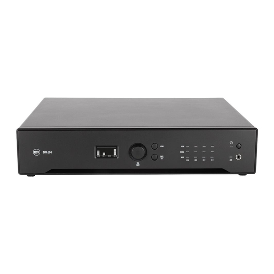
Page 12: Front Panel
FRONT PANEL Display (OLED). When no menu is selected, the current output levels are displayed as bars. Rotary encoder and push-button to select. Turn the encoder either clockwise to increase the MASTER VOLUME level or counterclockwise to decrease it. Press it to toggle MUTE ALL / UNMUTE ALL. In the edit mode (after pressing MENU [3]): turn the encoder either clockwise to scroll the menu downwards or increase the selected parameter value, turn it counterclockwise to scroll the menu upwards or decrease the selected parameter value. -
Page 13: Rear Panel
REAR PANEL AUDIO INPUT 1 (left / right channels): unbalanced line level input with RCA socket. If a jack plug is inserted into the front panel AUX input [7], the rear panel audio INPUT 1 is momentary disabled. [10] AUDIO INPUT 2 (left / right channels): unbalanced line level input with RCA socket. [11] AUDIO OUTPUT (left / right channels) / SUB OUT: unbalanced line level output with RCA socket. - Page 14 [15] SPEAKER OUTPUTS A-B Speakers outputs A-B allow either two channels for a low-impedance connection or a single 70 V line for speakers having matching transformers. Connector: EUROBLOCK (removable screw terminal block). TWO CHANNELS (A, B) -- - LOW IMPEDANCE CONNECTION Connect speakers as shown in the figure.
- Page 15 As alternative (when no BM 404 microphones are connected), BM input can also be used as additional auxiliary input by connecting the first three pins only. [20] BUS input (RJ45 socket): it needs to be linked to the BUS output of the previous DMA 504 unit. BUS AUDIO OUTPUT WIRE...
-
Page 16: Operational Modes
OPERATIONAL MODES After inserting the correct password (menu: SETTING > PASSWORD), it is possible to set the DMA 504 operational mode among the three different ones: MONO, STEREO, BRIDGE. To activate the stereo mode, in the menu select the STEREO MODE parameter and turn it on. - Page 17 DMA 504 can manage stereo inputs. STEREO 1 is the common volume for both left (A) and right (B) channels. OUT 1L and the OUT 1R are the single channel volume controls (useful for balance). The same behaviour is applied to the CD output pair, managed as STEREO 2.
-
Page 18: Display Menu
DISPLAY MENU Press the front panel MENU button to enter the edit mode and select the menu home page. Turn the rotary encoder either clockwise to scroll the menu downwards or increase the selected parameter value, turn it counterclockwise to scroll the menu upwards or decrease the selected parameter value. Press the rotary encoder to select (and enter a submenu). - Page 19 MAIN MENU -- - STEREO1 MODE STEREO1 Enter the STEREO1 menu Enter the OUT menu for the left channel (OUT A) only OUT 1L OUT 1R Enter the OUT menu for the right channel (OUT B) only OUT C Enter the OUT menu for OUT C only OUT D Enter the OUT menu for OUT D only ALL OUT...
- Page 20 MAIN MENU -- - BRIDGE1 (70V) BRIDGE1 Enter the BRIDGE1 menu Enter the OUT menu for OUT C only OUT C OUT D Enter the OUT menu for OUT D only ALL OUT Enter the ALL OUT menu INPUTS Enter the INPUT menu BUS OUT Enter the BUS OUT menu SETTING...
- Page 21 Enter the SETTING menu SETTING MAIN MENU -- - BRIDGE1 (70V) and BRIDGE2 (70V) BRIDGE1 Enter the BRIDGE1 menu BRIDGE2 Enter the BRIDGE2 menu ALL OUT Enter the ALL OUT menu INPUTS Enter the INPUT menu Enter the BUS OUT menu BUS OUT SETTING Enter the SETTING menu...
- Page 22 EXT L is overwritten by BUS IN 3 EXT R is overwritten by BUS IN 4 If the additional DANTE board is present: IN 2L is overwritten by DANTE IN 1 IN 2R is overwritten by DANTE IN 2 EXT L is overwritten by DANTE IN 3 EXT R is overwritten by DANTE IN 4 After entering the INPUT menu, select an audio input to edit its parameters.
-
Page 23: Rc 401 Remote Controls
RC 401 REMOTE CONTROLS RC 401 is a wall mount remote that works in combination with DMA 504 units. It can be connected to each power output and allows adjusting the output volumes, muting them or selecting the desired input program. - Page 24 4 CHANNELS MONO One RC 401 connected to each power output, acting on each VOLUME, MUTE and SELECT INPUT. STEREO CONFIGURATION One RC 401 connected to each power output pair AB and CD, set as STEREO 1 and STEREO 2. The connection shall be done to A and C connectors only.
- Page 25 BRIDGE CONFIGURATION One RC 401 connected to each power output pair AB and CD, set as BRIDGE 1 and BRIDGE 2. The connection shall be done to A and C connectors only. RC 401 connected to A acts, at the same time, on OUT A and OUT B VOLUME and MUTE.
-
Page 26: Avvertenze Per La Sicurezza
RCF S.p.A. non si assume alcuna responsabilità per l’installazione e / o l’uso errati di questo prodotto. - Page 27 Verificare inoltre l’idoneità della superficie di supporto a cui è ancorato il prodotto (parete, soffitto, struttura, ecc.) a dei componenti utilizzati per il fissaggio (tasselli, viti, staffe non fornite da RCF ecc.) che devono garantire sicurezza del sistema / installazione nel tempo, anche considerando, ad esempio, le vibrazioni meccaniche normalmente generate dai trasduttori.
- Page 28 Non utilizzare solventi, alcool, benzene o altre sostanze volatili per pulire le parti esterne di questo prodotto. NOTE IMPORTANTI Per evitare il verificarsi di disturbi sui cavi di segnale in linea, utilizzare solo cavi schermati ed evitare di avvicinarli a: Apparecchiature che producono campi elettromagnetici ad alta intensità...
- Page 29 È probabile che il funzionamento di questa apparecchiatura in un'area residenziale provochi interferenze dannose, nel qual caso l'utente dovrà correggere l'interferenza a proprie spese. Modifiche: qualsiasi modifica apportata a questo dispositivo che non sia approvata da RCF può annullare l'autorizzazione concessa all'utente dalla FCC di utilizzare questa apparecchiatura.
-
Page 30: Descrizione E Caratteristiche Principali
DMA 504 eroga una potenza di 4 x 500W RMS su 4 Ω oppure 2 x 1000W su linea a tensione costante 70 V. L’amplificatore DMA 504 può essere posto su banco oppure installato in un armadio rack 19” (grazie all’accessorio in dotazione). -
Page 31: Disimballaggio, Installazione E Raffreddamento
È sempre consigliabile conservare i materiali d’imballaggio, anche se l’amplificatore è arrivato in buone condizioni; il cavo d’alimentazione è incluso. Gli amplificatori DMA 504 possono essere installati in un armadio rack da 19” (con l’accessorio in dotazione). Non devono essere installati in un luogo con: temperatura troppo elevata, polvere o umidità... -
Page 32: Diagramma A Blocchi Del Segnale Audio
NOTE • La gestione attraverso RDNet disabilita ogni altra modalità di controllo (comandi da pannello frontale e contatti logici). • Una volta disconnesso RDNet, i parametri vengono mantenuti nello stato in cui si trovano nel software fino a quando non viene eseguita una qualsiasi azione su pannello frontale o contatti logici. -
Page 33: Pannello Frontale
PANNELLO FRONTALE Display (OLED). Quando nessun menu e selezionato, i livelli correnti dei segnali audio d’uscita sono visualizzati come barre. Encoder rotativo e pulsante per selezionare. Ruotare l’encoder in senso orario per aumentare il volume principale (MASTER VOLUME) o in senso antiorario per diminuirlo. Premerlo per mettere tutto in “mute” (disattivato) o ripristinare il suono. -
Page 34: Pannello Posteriore
PANNELLO POSTERIORE Ingresso audio IN 1 (canali destro e sinistro): ingresso di linea sbilanciato con presa RCA. Se un connettore jack e inserito nell’ingresso AUX del pannello frontale, l’ingresso IN 1 sul retro e momentaneamente disabilitato. [10] Ingresso audio IN 1 (canali destro e sinistro): ingresso di linea sbilanciato con presa RCA. [11] Uscita audio OUT (canali destro e sinistro) / SUB: uscita di linea sbilanciata con presa RCA. - Page 35 [15] USCITE ALTOPARLANTI A-B Le uscite per altoparlanti dell’amplificatore DMA 504 consentono connessioni a bassa impedenza su due canali oppure una singola linea da 70 V per diffusori acustici con trasformatore. Connettore: EUROBLOCK (morsettiera a vite rimovibile). DUE CANALI (A, B) COLLEGAMENTO A BASSA IMPEDENZA Collegare gli altoparlanti come mostrato in figura.
- Page 36 Bianco -- - marrone Marrone [21] Uscita BUS output (RJ45 socket): it needs to be linked to the BUS input of the next DMA 504 unit. [22] Pannello cieco da rimuovere durante l’installazione della scheda opzionale DANTE. Interruttore principale: premere per accendere (I) oppure spegnere (O) l’amplificatore.
-
Page 37: Modalità Di Funzionamento
MODALITÀ DI FUNZIONAMENTO Dopo aver inserito la password corretta (menu: IMPOSTAZIONI > PASSWORD), e possibile impostare la modalità di funzionamento tra le opzioni: MONO, STEREO, BRIDGE. Per scegliere la modalità STEREO, selezionare il parametro MODALITÀ STEREO ed impostarlo su ON; per scegliere la modalità BRIDGE (“a ponte”, singola linea a 70 V), selezionare il parametro MODALITÀ... - Page 38 STEREO L’amplificatore DMA 504 può gestire ingressi stereo. STEREO 1 e il volume comune per entrambi i canali sinistro (A) e destro (B). USCITA 1L e USCITA 1R sono i controlli di volume per i singoli canali (utili per il bilanciamento).
-
Page 39: Menu Impostazioni
MENU IMPOSTAZIONI Premere il tasto MENU del pannello frontale per accedere al menu principale (HOME). Ruotare l’encoder in senso orario per scorrere il menu verso il basso od aumentare il valore del parametro selezionato, ruotarlo in senso antiorario per scorrere il menu verso l’alto o ridurre il valore del parametro selezionato. Premere l’encoder per selezionare (od entrare eventualmente in un sottomenu). - Page 40 MAIN MENU -- - MODALITÀ STEREO2 USCITA A si accede al menu USCITA per la sola uscita A si accede al menu USCITA per la sola uscita B USCITA B STEREO2 si accede al menu STEREO2 USCITA 2L si accede al menu USCITA per il solo canale sinistro (uscita C) USCITA 2R si accede al menu USCITA per il solo canale destro (uscita D) TUTTE LE USCITE...
- Page 41 si accede al menu TUTTE LE USCITE TUTTE LE USCITE INGRESSI si accede al menu INGRESSI si accede al menu USCITE BUS USCITE BUS IMPOSTAZIONI si accede al menu IMPOSTAZIONI MAIN MENU -- - STEREO1 e BRIDGE2 (70V) STEREO1 si accede al menu STEREO1 si accede al menu USCITA per il solo canale sinistro (uscita A) USCITA 1L USCITA 1R...
- Page 42 MENU USCITE / STEREO / BRIDGE VOLUME Regola il livello del volume di entrambe le uscite Silenzia (ON) o ripristina (OFF) entrambe le uscite MUTE Seleziona l'ingresso audio tra: IN 1, IN 2, EXT (ingresso riservato per SEL. INGRESSO schede opzionali), BAL IN, BM (se usato da ingresso aux), IN 1L, IN 1R, IN 2L, IN 2R, EXT L, EXT R MODALITÀ...
- Page 43 Dopo aver scelto BAL IN, sono disponibili ulteriori due parametri: LIVELLO LINE/MIC imposta il livello dell'ingresso BAL IN come LINE oppure MIC attiva (se impostato su ON) la funzione VOX (priorità automatica quando e rilevato un segnale audio all'ingresso BAL IN) ed e possibile impostare il livello di soglia MENU BUS OUT Dopo essere entrati nel menu delle uscite BUS, selezionare un CANALE (1, 2, 3, 4) oppure SUB /...
-
Page 44: Controlli Remoti Rc 401
DMA e permette di regolarne il volume di uscita, attivare il mute e selezionare il programma in ingresso. Quando collegato ad una unità DMA 504, RC 401 è il solo controllo per il volume di uscita, mentre i controlli corrispondenti nel menu dell’unità DMA 504 risultano disattivati. - Page 45 4 CANALI MONO Un controllo RC 401 collegato ad ogni uscita di potenza, che agisce su ciascun VOLUME, MUTE e SEL INGRESSO. CONFIGURAZIONE STEREO Un controllo RC 401 collegato ad ogni coppia di uscite di potenza AB e CD, impostate come STEREO1 e STEREO2. La connessione deve essere fatta solamente ad A e C.
- Page 46 CONFIGURAZIONE BRIDGE “A PONTE” Un controllo RC 401 collegato ad ogni coppia di uscite di potenza AB e CD, impostate come BRIDGE1 e BRIDGE2. La connessione deve essere fatta solamente ad A e C. Il controllo collegato ad USCITA A agisce, allo stesso tempo, su VOLUME e MUTE di USCITA A ed USCITA B.
-
Page 47: Dimensions / Dimensioni
DIMENSIONS / DIMENSIONI... -
Page 48: Specifications / Specifiche Tecniche
SPECIFICATIONS / SPECIFICHE TECNICHE DMA 504 Amplifier specifications Amplifier Class: Number of channels: Power output per channel (@ 2.7 ohm): 700 W RMS (Max 1000W for A+B and C+D) Power output per channel (@ 4 ohm): 500 W RMS Power output per channel (@ 8 ohm):... - Page 49 DMA 504 Fuses: VHF (Very High Frequencies): Power requirement Operating voltage: 90-240 V~ 50/60Hz Power consumption: 800 W Standard compliance CE marking: Physical specifications Cabinet/Case Material: Metal Color: Black Rack mounting: 19", 2U Size Height: 96 mm / 3.78 inches Width: 430 mm / 16.93 inches...
- Page 52 RCF S.p.A. Via Raffaello Sanzio, 13 - 42124 Reggio Emilia – Italy 10307721 B Tel +39 0522 274 411 - Fax +39 0522 232 428 - e-mail: info@rcf.it - www.rcf.it...
Need help?
Do you have a question about the DMA 504 and is the answer not in the manual?
Questions and answers