Table of Contents

Related Manuals for RCF MS520


Summary of Contents for RCF MS520
- Page 1 MS520 CONTROL AND AMPLIFICATION UNIT FOR MUSIC AND PAGING DISTRIBUTION UNITÀ DI CONTROLLO E AMPLIFICAZIONE PER LA DISTRIBUZIONE DI MUSICA E ANNUNCI User manual Manuale d’uso the rules of sound...
-
Page 2: Avvertenze Per La Sicurezza
L’installazione e l’utilizzo errati del prodotto esimono la RCF S.p.A. da ogni responsabilità. ATTENZIONE: Per prevenire i rischi di fiamme o scosse elettriche, non esporre mai questo prodotto alla pioggia o all’umidità... -
Page 3: Note Importanti
Verificare inoltre l’idoneità del supporto (parete, soffitto, struttura ecc., al quale è ancorato il prodotto) e dei componenti utilizzati per il fissaggio (tasselli, viti, staffe non fornite da RCF ecc.) che devono garantire la sicurezza dell’impianto / installazione nel tempo, anche considerando, ad esempio, vibrazioni meccaniche normalmente generate da un trasduttore. -
Page 4: Disimballo Ed Installazione
RCF S.p.A. Vi ringrazia per l’acquisto di questo prodotto, realizzato in modo da garantirne l’affidabilità e prestazioni elevate. DISIMBALLO ED INSTALLAZIONE Si consiglia di dedicare alcuni minuti alla lettura di questo manuale per assicurare la corretta installazione del prodotto e conoscerne le caratteristiche. -
Page 5: Pannello Frontale
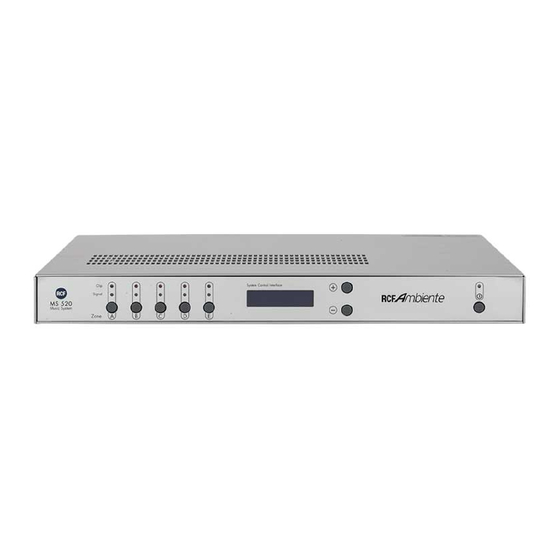
PANNELLO FRONTALE 5 tasti selettori di zona (A, B, C, D, E) e di pagina del menù di utilizzo o di configurazione. 5 LED verdi indicanti la presenza del segnale su ciascuna delle 5 uscite / zone. 5 LED rossi indicanti la saturazione del segnale (“clip”) su ciascuna delle 5 uscite / zone. Display LCD retroilluminato (16 caratteri x 2 linee). -
Page 6: Pannello Posteriore
PANNELLO POSTERIORE Paging IN “ ”: ingresso audio bilanciato (con alimentazione “Phantom” attivabile impostando entrambi i microinterruttori “Phantom” su ON) per un GND: massa microfono (impostando entrambi i microinterruttori “Line/Mic” su “Mic”) od un “ ”: polo positivo – segnale con livello “linea” (impostando entrambi i microinterruttori “Line/Mic” “... - Page 7 ÷ Nota: tutti gli ingressi /uscite audio con connettore di tipo RCA, sono per segnali a livello “linea” (non microfonici). Music IN 1 Ingresso audio “ ” (L: canale sinistro R: canale destro) a cui collegare l’uscita di una sorgente musicale (es. lettore CD, riproduttore di cassette, sintonizzatore radio, ecc…). Music IN 2 Ingresso audio “...
-
Page 8: Uscite Audio
TABELLA USCITE A / B MODALITA’ USCITE AUDIO Direct OUT A Direct OUT B SUB OUT A Direct OUT B (A left) (A right) (A left + right) or SUB OUT A (mono, con/senza crossover) subwoofer zona A zona B zona B B “crossover”... - Page 9 Doppia presa per morsetti a vite a 4 poli rimovibili Paging Control Inputs “ ” (da destra verso sinistra) +Vcc: tensione (ca. 8,5 V c.c. rispetto alla massa “GND”) disponibile per l’eventuale alimentazione del microfono per annunci. Priority: Il collegamento momentaneo (ad esempio, tramite un pulsante) del contatto “Priority”...
- Page 10 “ ” (il programma che regola il funzionamento dell’apparecchio). Consiglio: prima di contattare il rivenditore (o un nostro centro RCF MS 520 d’assistenza tecnica) per eventuali problemi di funzionamento, annotate Firmware V1.0 firmware il numero (es. 1.0) della versione del “...
- Page 11 Zone A Bass Un’ulteriore pressione del tasto “ ” attiva il terzo parametro “ ”: il controllo dei toni bassi. Utilizzare il tasto + per aumentare i bassi, il tasto – per attenuarli. Nota: la doppia barra centrale indica lo zero, ovvero nessuna correzione zA Bass dei bassi.
- Page 12 sola zona A Balance Per la , è presente un parametro addizionale “ ” (posto dopo quello del volume). Questo permette di regolare il bilanciamento del livello di volume tra i canali sinistro e destro. zA Balance La doppia barra centrale indica l’equità tra i canali sinistro e destro. zA Balance Il canale destro è...
-
Page 13: Aux Level
AUX LEVEL Direct Sono disponibili 5 controlli (1 per ciascuna zona) del livello d’uscita delle uscite ausiliarie (“ SUB OUT ” / “ ”, con connettori di tipo RCA). zA AUX Level Nota: nel caso che il controllo sia posto a zero, il livello delle uscite zA AUX Level ausiliarie sarà... -
Page 14: Max Volume
zC AUX X-over Direct OUT C SUB OUT L’uscita “ ” è tagliata a 130 Hz. Low Pass 130Hz [zona D e zona E]: Direct OUT D SUB OUT Direct OUT E vedi impostazioni della zona C, ma inerenti alle uscite “ ”... - Page 15 DIRECT IN GAIN Direct Regolazione della sensibilità comune a tutti gli ingressi diretti “ Direct IN Gain ”. MIC / LINE BASS Mic / Line Bass Paging IN Controllo dei toni bassi dell’ingresso “ ” MIC / LINE TREBLE Mic / Line Treble Paging IN Controllo dei toni alti dell’ingresso “...
- Page 16 WAKE UP MODE Si può definire a priori quale sarà lo stato iniziale delle zone dopo l’accensione dell’apparecchio. Lo stato di ciascuna zona è esattamente quello precedente allo spegnimento Wake Up Mode dell’apparecchio. Last Mute State Tutte le zone sono poste inizialmente in “mute”. Wake Up Mode Zones Muted Lo stato di ciascuna zona è...
-
Page 17: Installazione
CONTROLLI REMOTI RC 62 INSTALLAZIONE Utilizzare come supporto un “falso polo” (un tappo copri-foro) da 1 modulo per comuni scatole “portafrutti” usate negli impianti elettrici. Rimuovere le eventuali nervature centrali utilizzando delle tenaglie. Forare il “falso-polo” al centro utilizzando un trapano (diametro del foro: 14 mm) - Page 18 Inserire la guarnizione cilindrica nel “falso-polo”, avvitandola nel dado quadrato utilizzando la chiave in dotazione. Inserire posteriormente la staffa d’ottone e fissarla avvitando il dado esagonale con la chiave in dotazione.
- Page 19 Inserire posteriormente il circuito stampato con la leva del joystick facendo attenzione al verso (“up” :sopra; “down”: sotto) e fissarlo aprendo le 2 alette interne della staffa d’ottone. Inserire il circuito stampato con i 2 connettori “RJ 45” facendo attenzione al verso (“up”...
- Page 20 Inserire il joystick sul lato anteriore; il controllo remoto è ora pronto per essere montato sul telaio-supporto “portafrutti” ed installato dentro una scatola (ad incasso o sporgente). Collegare il cavo / i cavi “CAT5” ad uno o entrambi i connettori “RJ45”.
- Page 21 UTILIZZO CAVO “CAT5” (per il collegamento dei controlli remoti RC 62) Il colore della retro-illuminazione del joystick indica l’attuale stato del sistema e della zona pin to pin non illuminato “ ” (1 con 1, 2 con 2, 3 con 3, ecc...) controllata.
-
Page 22: Dati Tecnici
DATI TECNICI • Potenza uscite altoparlanti: 5 x 20 W R.M.S. (4 Ω) • Sensibilità: Ingressi “Music IN” : -16 dBu (120 mV) Ingressi “Direct IN”: -16 dBu (120 mV) Ingresso “Paging IN”: LINE -43 dBu ÷ -27 dBu (5,5 ÷ 35 mV) MIC -58 dBu ÷... - Page 23 PABX 2X1,5mm twisted CAT5 2X1,5mm twisted 2X1,5mm twisted CAT5 Potenza per ogni zona: 20W on 4 Ohm Risposta in frequenza: 20 Hz - 20 KHz THD del Sistema: 0,05% Rapporto S/N MIC/LINE: > 70dB/85dB PABX 2X1,5mm twisted CAT5 2X1,5mm twisted CAT5 2X1,5mm twisted...
-
Page 24: Important Notes
RCF S.p.A. will not assume any responsibility for the incorrect installation and / or use of this product. -
Page 25: Operating Precautions
(screw anchors, screws, brackets not supplied by RCF etc.), which must guarantee the security of the system / installation over time, also considering, for example, the mechanical vibrations normally generated by transducers. -
Page 26: Unpacking And Installation
RCF S.p.A. would like to thank you for purchasing this product, which has been designed to guarantee reliability and high performance. UNPACKING AND INSTALLATION We recommend you take a few minutes to read this manual to ensure the correct product installation and become familiar with its features. -
Page 27: Front Panel
FRONT PANEL 5 zone (A, B, C, D, E) / menu page keys. 5 green LED indicating the signal presence on each zone / output. 5 red LED indicating the signal peaks (clipping) on each zone / output. Backlit LCD display (16 characters x 2 lines). Key (-): it decreases the value of the selected parameter. -
Page 28: Rear Panel
REAR PANEL Paging IN “ ”:balanced audio input (with “Phantom” power supply when both “Phantom” DIP switches are set to ON) for either a paging GND: ground microphone (when both “Line/Mic” DIP switches are set to “Mic”) or a “ ”: signal (hot) –... - Page 29 ÷ Note: all audio inputs / outputs with RCA type connector are for “line” level signals (not for microphones). Music IN 1 “ ” audio input (L: left channel R: right channel) for a music source (e.g.. CD player, cassette recorder, tuner, etc...). Music IN 2 “...
-
Page 30: Audio Outputs
OUTPUTS A / B MODE AUDIO OUTPUTS Direct OUT A Direct OUT B SUB OUT A Direct OUT B (A left) (A right) (A left + right) or SUB OUT A (mono, crossover ON/OFF) subwoofer zone A zone B zone B B “crossover”... - Page 31 Paging Control Inputs “ ” Double socket for removable 4 pole screw terminals. (from right to left) +Vcc: available voltage (ca. 8.5 V dc, ref. “GND”) to power a paging microphone. Priority: A momentary link (for instance, through a pushbutton) of the pin “Priority” to “GND” temporary increases the volume levels (ca.
- Page 32 After turning the unit on, the current firmware release appears on the LCD display (a few seconds). SUGGESTION: before contacting your dealer about possible technical RCF MS 520 firmware problems, please note the release number , i.e. 1.0 (if the unit Firmware V1.0...
- Page 33 Zone A Bass Push the “ ” key for the third time to edit the parameter “ ” (bass control). Use the key + to increase the level, the key – to decrease it. zA Bass Note: the double central bar is the flat position (no tone control). zA Bass The gain is indicated by a bar to the right.
- Page 34 CONFIGURATION MENU (FOR INSTALLERS ONLY) This menu includes all the necessary parameters to configure the unit, hence it is advisable to pay attention and evaluate the real need to edit carefully. stand-by When the unit is in , push the on / stand-by key (see no. 7 in the front panel description) zA AUX leve and held it pushed for some seconds (until the LCD display shows the parameter “...
- Page 35 [zone B, 5 zone mode] Direct OUT B SUB OUT full-range zB AUX X-over The output “ ” is (hence it provides Direct OUT B (A right) Full Range the same signal of the output “ ” ). zB AUX X-over Direct OUT B SUB OUT The output “...
- Page 36 Music IN 3 “ ” detects the signal presence on the “ ” input, which VOX Selection gets the priority in all zones where the music programme no.1 or no.2 is PGM3 Input Direct IN selected (but not in zones assigned to “ ”).
-
Page 37: Standby Mode
PAGE CHIME Page Chime Paging IN ON/OFF “ ” input chime selector STAND-BY MODE It is possible to disable the remote control RC 62 standby command (keep pressing the joystick central button for some seconds). Stand-By Mode The main unit MS 520 can be put on standby by remote controls RC 62. Main &... -
Page 38: Installation
RC 62 REMOTE CONTROLS INSTALLATION Use a blank key Remove all ribs for common (if present) by using tongs. electric wall surface/flush- mounted boxes. Drill the blank key in the centre (hole diameter: 14 mm). Insert the cylindrical packing into the blank key hole and screw it into the nut by using the provided tool. - Page 39 On the rear side, insert the brass bracket and fix it with the hexagonal nut. On the rear side, insert the P.C.B. including the joystick control (paying attention to its side, up and down) and fix it by opening the 2 internal wings of the brass bracket.
- Page 40 Insert the P.C.B. with the 2 “RJ 45” sockets (paying attention to its side, up and down) and fix it by opening the 2 external wings of the brass bracket. Insert the joystick in the front. The remote control is now ready to be mounted into a support for a wall mounted box.
-
Page 41: Joystick Controls
CAT5 CABLE (to connect remote controls RC 62) The joystick is backlit. The light colour indicates the system / zone status. “pin to pin” no light OFF - MS 520 The unit is OFF through the main switch on the rear panel. It is not possible to turn the system on from remote controls. -
Page 42: Specifications
SPECIFICATIONS • Output power to loudspeakers: 5 x 20 W R.M.S. (4 Ω) • Sensitivity: “Music IN” inputs: -16 dBu (120 mV) “Direct IN” inputs: -16 dBu (120 mV) “Paging IN” input: LINE -43 dBu ÷ -27 dBu (5.5 ÷ 35 mV) MIC -58 dBu ÷... - Page 43 PABX 2X1,5mm twisted CAT5 2X1,5mm twisted 2X1,5mm twisted CAT5 Potenza per ogni zona: 20W on 4 Ohm Risposta in frequenza: 20 Hz - 20 KHz THD del Sistema: 0,05% Rapporto S/N MIC/LINE: > 70dB/85dB PABX 2X1,5mm twisted CAT5 2X1,5mm twisted CAT5 2X1,5mm twisted...
- Page 44 Except possible errors and omissions. RCF S.p.A. reserves the right to make modifications without prior notice. the rules of sound RCF SpA: Via Raffaello, 13 - 42010 Reggio Emilia Italy > tel. +39 0522 274411 - fax +39 0522 274484 - e-mail: rcfservice@rcf.it...
Need help?
Do you have a question about the MS520 and is the answer not in the manual?
Questions and answers