Table of Contents
Advertisement
Quick Links
Advertisement
Table of Contents

Related Manuals for Vitek VT-DVR04


Summary of Contents for Vitek VT-DVR04
- Page 1 VT-DVR04 4 CHANNEL DIGITAL VIDEO RECORDER User’s Manual Version 2.1...
-
Page 2: Table Of Contents
TABLE OF CONTENTS Forward Safety and Precautions Getting Started Front Panel Power Audio Selector Video Selector Playing Back Recorded Images System Status LED System Status LED Remote Control Sensor USB Port Rear Panel AC Power Socket (100V-260V) Video Output Terminal (BNC Connector) Audio In Terminal Video Export (RCA Connector) Video Export (RCA Connector) -
Page 3: Forward
VT-DVR04 is a state of the art DVR security system that can be monitored from anywhere in the world through a Network Interface Card (NIC) and a DSL or secured line. -
Page 4: Getting Started
Getting Started The following items are included with the VT-DVR04. Please be certain that all items are included upon opening the carton: 1. Components o VT-DVR04 (main component) o Remote Control (batteries included) o Power Cable o User’s Manual o Warranty Card... -
Page 5: Front Panel
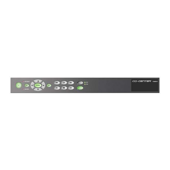
Product Information 1. Front Panel 1. Power Power On/Off Button. Power Off is indicated by RED and Power On status is indicated by GREEN. To turn the system on, press the Power key. The key should turn amber. Enter the password (default is 1111) using the remote control and press the power key again. -
Page 6: Playing Back Recorded Images
4 & 5. Playing Back Recorded Images The Playback buttons consist of Frame Advance, Fast Forward, Forward Play, Stop, Reverse Play, and Fast Reverse. To get to the playback mode, simply press any one of the playback buttons. Then press the STOP button. This will take the user to the time selector mode. -
Page 7: Rear Panel
2. Rear Panel 1. AC Power Socket (100V-260V) Insert the provided accessory power cord here. 2. Video Input Terminal (BNC Connector) There are total of four camera inputs. 3. Video Output Terminal (BNC Connector) Main Monitor. Live and Playback is shown with the On Screen Display (OSD). -
Page 8: Audio In Terminal
4. Audio In Terminal System can record up to two audio inputs. 5. Video Export (RCA Connector) System will export recorded images to a VCR or to TV. This allows The user to record desired footage in VTR analog format. 6. -
Page 9: Remote Control
3. Remote Control Power On/Off Event Log OSD On/Off M/D (motion detection) Area indicator On/Off Network Status Indicator Sensor Off (S1-S2) Alarm On/Off Video Selector Audio Selector 10. Playback Controls 11. Directional keys and Enter 12. Menu 13. Exit 14. P/T/Z/F 15. -
Page 10: Using The Remote Control
Using the Remote Control There are two methods of configuring the VT-DVR04: from the site where VT-DVR04 Is installed and through the Network Connection. Following are the description for configuring the VT-DVR04 at the site. For Remote Access Configuration, please refer to the REMOTE software User’s Guide. -
Page 11: Remote Control Functions
REMOTE CONTROL FUNCTIONS 1. Power On/Off Power On/Off Button. Power Off is indicated by RED and On status is indicated by GREEN. To turn the system on, press the Power key. The key should turn amber. Enter the password (default is 1111) and press the power key again. The key should turn green and the system should become active. -
Page 12: Audio Selector
9. Audio Selector Select button: Can select between CH1 and CH2. During Live View mode, audio monitoring is possible. During Playback mode, user can listen to the recorded audio. Mute button: Mutes the audio function. 10. Playback Controls The Playback buttons consist of Frame Advance, Fast Forward, Forward Play, Stop, Reverse Play, and Fast Reverse. -
Page 13: Menu - System Configuration
Menu – System Configuration In Live viewing mode, press the menu button on the remote control. Enter the password (factory default is 2222). A graphic illustration of setup options will be displayed. 1) Recording Schedule – Using the left/right cursor and the enter button to select time periods for event or continuous recording. - Page 14 T/D Change – Enter the correct Time/Date and Format to be displayed on the OSD. The system can display Month/Day/Year or Day/Month/Year. Remote Control – Enter remote control ID when using more than 1 unit in the same proximity. Color Tune – Each camera can be adjusted individually for brightness, contrast, saturation and hue.
-
Page 15: Trouble Shooting
TROUBLE SHOOTING 1. Power switch does not function. o Connect the AC power cord securely. o Make sure that POWER key is RED (illuminated). o If the POWER key is RED, input the Password using the [A1]-[D4] buttons and press the POWER key again. o If the problem persists, please contact the professional installer or the security manager. - Page 16 9970 GLENOAKS BLVD. UNIT B SUN VALLEY, CA 91352 PHONE: 888-VITEK-70 818-771-0300 FAX: 818-771-0400 WWW.VITEKCCTV.COM...
Need help?
Do you have a question about the VT-DVR04 and is the answer not in the manual?
Questions and answers