Table of Contents
Advertisement
Quick Links
MainsPro
G99TT
SW version 1.0.0
1 Document information
2 Introduction of Installation and Operation Guide
3 Installation data
4 User interface
5 Introduction of Application Guide
6 Important Steps of MainsPro G99TT utilization
7 TRIP and Fault Reset
8 Protective features
9 Application tips
10 Introduction of Reference Guide
11 Technical data
12 Appendix
Copyright © 2022 ComAp a.s.
Written by Vladimír Zubák
Prague, Czech Republic
ComAp a.s., U Uranie 1612/14a,
170 00 Prague 7, Czech Republic
Tel: +420 246 012 111
E-mail: info@comap-control.com, www.comap-control.com
Mains Decoupling Protection
Global Guide
Relay
6
8
10
19
29
30
31
33
40
44
45
52
Advertisement
Table of Contents

Related Manuals for ComAp MainsPro G99TT


Summary of Contents for ComAp MainsPro G99TT
- Page 1 2 Introduction of Installation and Operation Guide 3 Installation data 4 User interface 5 Introduction of Application Guide 6 Important Steps of MainsPro G99TT utilization 7 TRIP and Fault Reset 8 Protective features 9 Application tips 10 Introduction of Reference Guide...
-
Page 2: Table Of Contents
3.3.7 Binary switches connection 3.4 Measurement range 3.5 Wiring examples 4 User interface 4.1 Front panel elements 4.1.1 Pushbuttons 4.1.2 Setpoints change 4.1.3 Reset operation time 4.1.4 Reset trip counters 4.1.5 TEST mode activation 4.1.6 Factory default MainsPro G99TT 1.0.0 Global Guide... - Page 3 4.5 Alarm messages 5 Introduction of Application Guide 5.1 Purpose of this manual 5.2 MainsPro G99TT typical usage 5.3 Typical applications of MainsPro G99TT protection relay 6 Important Steps of MainsPro G99TT utilization 7 TRIP and Fault Reset 7.1 TRIP 7.1.1 TRIP event...
- Page 4 11.1.4 Time delays accuracy 11.1.5 Loss of Mains reaction times 11.2 Technical parameters 11.2.1 Endurance to the power supply voltage fails 11.3 Factory default setting of MainsPro G99TT unit 12 Appendix 12.1 Library of Setpoints 12.1.1 Group: Basic 12.1.2 Group: V <>, A.V <>...
- Page 5 12.3.13 LOM Sig 12.3.14 !LOM Sig 12.3.15 dU Sig 12.3.16 !dU Sig 12.3.17 Other Sig 12.3.18 !Other Sig 12.3.19 Alt Sig 12.3.20 TrpEndImp 12.3.21 !TrpEndImp 12.3.22 InternFail 12.3.23 !InternFail 12.3.24 BakTrpPer 12.3.25 !BakTrpPer 12.3.26 BakTrpImp 12.3.27 !BakTrpImp MainsPro G99TT 1.0.0 Global Guide...
-
Page 6: Document Information
Although MainsPro G99TT is very simple and intuitive for the operating personnel, we recommend keeping a hardcopy of this manual available permanently at the site where MainsPro G99TT unit is installed, to facilitate the necessary service and operation tasks. -
Page 7: Document History
End User's Guide/Manual without the prior written consent of ComAp is expressly prohibited! Even if the prior written consent from ComAp is acquired, ComAp does not take any responsibility for the content, trustworthiness and quality of any such translation. ComAp will deem a translation equal to this End User's Guide/Manual only if it agrees to verify such translation. -
Page 8: Introduction Of Installation And Operation Guide
Although MainsPro G99TT is very simple and intuitive for the operating personnel, we recommend keeping a hardcopy of this manual available permanently at the site where MainsPro G99TT unit is installed, to facilitate the necessary service and operation tasks. -
Page 9: Adjust The Setpoints
Note: ComAp believes that all information provided herein is correct and reliable and reserves the right to update at any time. ComAp does not assume any responsibility for its use unless otherwise expressly undertaken. -
Page 10: Installation Data
3 Installation data 3.1 Dimensions 3.2 List of terminals 3.3 Wiring 3.4 Measurement range 3.5 Wiring examples 6 back to Table of contents 3.1 Dimensions MainsPro G99TT 1.0.0 Global Guide... -
Page 11: List Of Terminals
In case of DC supply, connect "–" pole to this terminal 3.3 Wiring 3.3.1 "Star" connection 3.3.2 "Delta" connection 3.3.3 Connection with voltage transformers 3.3.4 Single-phase connection 3.3.5 Power supply 3.3.6 Relay outputs connection 3.3.7 Binary switches connection MainsPro G99TT 1.0.0 Global Guide... -
Page 12: Star" Connection
"Star" connection - MainsPro G99TT provides automatic detection of phase-neutral voltage measurement. MainsPro G99TT provides over-range to 130% of the rated voltage, i.e. 300 VAC for 230 V system and 156 V for 120 V system with no change of measurement accuracy. -
Page 13: Delta" Connection
3.3.2 "Delta" connection In this arrangement, MainsPro G99TT is rated for 400 VAC ph-ph with over-range to 130% = 520 VAC with no change of measurement accuracy. Setpoint Uin (page 54) is to be set to 400 V, no additional setting is necessary for indication of "Delta"... -
Page 14: Single-Phase Connection
3.3.5 Power supply MainsPro G99TT provides set of 3 terminals for the purpose of dual power supply range: 8 - 40 VDC: use the terminals + and N/- 85 - 265 VAC / 110-370 VDC: use the terminals L/+and N/-... -
Page 15: Relay Outputs Connection
DC voltage, due to galvanic interconnection of both circuits! 3.3.6 Relay outputs connection For safety purposes, it is recommended to set all MainsPro G99TT relay outputs to inverse logic for failure trips and signaling. This means that under fault-free conditions all contacts are kept in energized position. In trip or out-of-range signaling state, the contacts de-energize. -
Page 16: Binary Switches Connection
Uin (page 54) to 230/400V. MainsPro G99TT will adjust automatically the measurement method, to assure the defined accuracy for the measured voltage 230 V. 400 V - this range applies in case of "delta" connection of the 3-phase system using nominal 400V phase to phase. - Page 17 2. Under normal conditions the Off coil is not powered and contacts are open. In case of failure, the contacts (12) close and the voltage is applied on the Off coil, therefore auxiliary power supply (e.g.UPS) is necessary to provide voltage for the Off coil. MainsPro G99TT 1.0.0 Global Guide...
- Page 18 3. Under normal conditions the contacts are closed, in case of failure the contacts open. This wiring is typically used for coil driven contactors. 6 back to Installation data MainsPro G99TT 1.0.0 Global Guide...
-
Page 19: User Interface
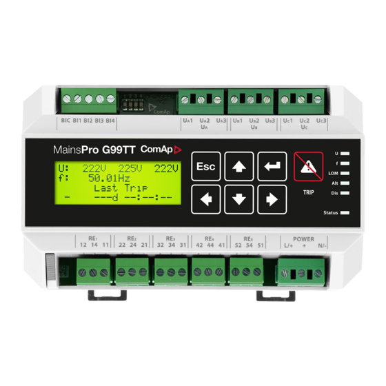
6 back to Table of contents 4.1 Front panel elements Number Description 4 x 20 Alpha-numerical display Mechanical sealing indication Frequency measurement 3-phase voltage measurement Last trip indication Last trip timer Control and navigation pushbuttons Fault Reset button MainsPro G99TT 1.0.0 Global Guide... -
Page 20: Pushbuttons
Note: The unit allows mechanical sealing of selected setpoints by the black switch in left-bottom corner of the unit (for information what setpoints are sealing protected see Factory default setting of MainsPro G99TT unit (page 47)). If locked, the icon of closed padlock will appear on the position of setpoint change and the setpoints may not be changed. -
Page 21: Reset Operation Time
3. Using ← and → choose the required operation. By selecting YES, you will activate the TEST mode - see the chapter TEST mode (page 42) in Application Guide. Press ENTER to confirm your selection. 4. By selecting NO and pressing ENTER or by pressing ESC, return to the measurement screens with no change. MainsPro G99TT 1.0.0 Global Guide... -
Page 22: Factory Default
47). 4.3 Signalization LEDs There are 7 LEDs for indication of MainsPro G99TT status with the meaning indicated in the table below In case of signaling different statuses by one LED, the following priorities apply, i.e. the higher priority signal is provided by the LED:... - Page 23 Together with LED U and f, indicates incorrect polarity of one Orange phase None of Vector shift or ROCOF failure is detected or neither Dark Vector shift nor ROCOF protections are not enabled by setpoint MainsPro G99TT 1.0.0 Global Guide...
-
Page 24: Measurement Screens
Color Meaning and no other indicated failure is sensed Indication of severe internal failure. Contact ComAp technical flashing support! Orange Indication of internal failure. Contact ComAp technical support! flahing Status Orange Indication of internal failure. Contact ComAp technical support! Green The unit is in operation with no internal problems. - Page 25 V negative: actual value of negative sequence voltage V positive: actual value of positive sequence voltage Negative sequence overvoltage and positive sequence undervoltage are methods of evaluation of angle asymmetry of the 3-phase voltage system. See more MainsPro G99TT 1.0.0 Global Guide...
- Page 26 Functions that are configured are displayed in the appropriate order. Its status is displayed in brackets. Relay outputs 1-4 status screen: Status of the first 4 MainsPro G99TT relay outputs. Name in parentheses marks the function assigned by the setpoints in group f(RE).
-
Page 27: Alarm Messages
Time measurement screen: since MainsPro G99TT was powered- Please note that the time information on the MainsPro G99TT unit is not measured by a calibrated RTC device and may serve for orientation purposes only. Find more in Technical data (page 45). - Page 28 Vneg Negative sequence overvoltage Vpos Positive sequence undervoltage Vavg 10 minutes floating average overvoltage Wrong phase rotation Wrong polarity of one phase Ext1 External trip Ext2 External trip Start Trip 6 back to User interface MainsPro G99TT 1.0.0 Global Guide...
-
Page 29: Introduction Of Application Guide
5.1 Purpose of this manual The Application Guide serves for the designers and engineers who process the necessary documentation and implementation procedures on the site where MainsPro G99TT is installed. It contains detailed description of MainsPro G99TT functionalities and their practical application. -
Page 30: Important Steps Of Mainspro G99Tt Utilization
6 Important Steps of MainsPro G99TT utilization This process describes a typical decisions and technical steps to follow in case of MainsPro G99TT utilization, if required by the distribution network operator (DNO). MainsPro G99TT 1.0.0 Global Guide... -
Page 31: Trip And Fault Reset
If the BI Disable is set to ENABLED and the BI Disable is activated during this state, the TRIP status is terminated and the fault is reset. If the BI Disable is set to ENABLEDexlTRP and the BI Disable is activated during this state, it will have no effect on the unit. MainsPro G99TT 1.0.0 Global Guide... -
Page 32: Fault Reset
The TRIP is active but any of the measured values is out of limits of normal operational state In such cases the Fault reset trigger is ignored. By a successful Fault reset, the TRIP status is terminated. 6 back to TRIP and Fault Reset MainsPro G99TT 1.0.0 Global Guide... -
Page 33: Protective Features
8 Protective features The following protective functionalities, referred also by their ANSI number, are available in MainsPro G99TT unit: 8.1 ANSI 59 Overvoltage, ANSI 27 Undervoltage 8.2 Floating 10 minutes average overvoltage 8.3 ANSI 81H Overfrequency, 81L Underfrequency 8.4 ANSI 47 Voltage unbalance and angle asymmetry 8.4.1 Voltage unbalance... -
Page 34: Floating 10 Minutes Average Overvoltage
When any of the preset thresholds is crossed, the appropriate LED signal is issued by LED f and the output f Sig (page 67) moves to fault-indicating position immediately. If the frequency keeps out of MainsPro G99TT 1.0.0 Global Guide... - Page 35 Both overfrequency and underfrequency protective stages provide possibility of setting 2 levels with independent delay assigned to each level. Note: MainsPro G99TT measures frequency on the phase L1 only, therefore frequency measurement will be distorted in case that a fault occurs in this phase.
-
Page 36: Ansi 47 Voltage Unbalance And Angle Asymmetry
8.4 ANSI 47 Voltage unbalance and angle asymmetry MainsPro G99TT provides 3 independent methods for evaluation of voltage symmetry failures. All of these protections are only active in case that 3-phase system is selected by the setpoint System (page 54). -
Page 37: Ansi 78 Vector Shift
Image 8.6 In parallel with the mains In case of mains failure or auto reclosing the generator suddenly feeds a very high consumer load. The rotor displacement angle is decreased repeatedly and the voltage vector g changes its direction to g’. MainsPro G99TT 1.0.0 Global Guide... -
Page 38: Rate Of Change Of Frequency (Rocof)
8.6 81R Rate Of Change Of Frequency (ROCOF) ROCOF is another fast "Loss of Mains" protection stage provided in MainsPro G99TT. It is based on a similar principle as Vector shift, i.e. dependence of the generator speed and voltage on the load size. The variations of frequency delivered by the gen-set depend on the load fluctuations and gen-set speed regulation capability. -
Page 39: Phase Rotation, Incorrect Phase Polarity
8.7 Phase rotation, incorrect phase polarity MainsPro G99TT provides check of the phase sequence and polarity. The correct connection is indicated in the wiring instructions e.g. on MainsPro G99TT box or in chapter... -
Page 40: Application Tips
9.2 Binary switches MainsPro G99TT allows basic remote control by means of binary signals wired from an external device to MainsPro G99TT binary switches. The signals may be also provided remotely, e.g. through radio or GSM communicator devices. As an example of such a device, see the uGATE communicator below. Ask for more information about this product at support@comap-control.com. -
Page 41: External Trip
MainsPro G99TT. Any time some protective function is activated and a trip is issued, deactivation of this binary input is expected. If the feedback does not confirm opening of the CB, additional... -
Page 42: Timer
MainsPro G99TT unit. Please note that MainsPro G99TT does not provide RTC clock and after each power-up of the unit, the time and date is lost. For this reason only indication of days / hh : mm is used. The accuracy of the time measurementhas been tested and a measurement error of 4 seconds per 24 hours was observed. - Page 43 Go to Test mode activation screen and select NO, or Turn the unit off and on again, or The unit goes back to the standard operation after 10 minutes from the last keyboard activity. 6 back to Application tips MainsPro G99TT 1.0.0 Global Guide...
-
Page 44: Introduction Of Reference Guide
10 Introduction of Reference Guide 10.1 Purpose of this manual The Reference Guide contains library of setpoints, inputs and outputs functionalities and detailed technical information. This information is referenced in the Installation and Operation Guide and Application Guide. MainsPro G99TT 1.0.0 Global Guide... -
Page 45: Technical Data
11.1 Accuracies and reaction times 11.1.1 Operating area MainsPro G99TT provides the below mentioned accuracies and reaction times in case that the measured voltage and frequency in all 3 phases is within the green area on the picture below. Outside of the green area, MainsPro G99TT provides the expected performance (i.e. -
Page 46: Voltage Measurement
120 V / 230 V ph-N / 400 V ph-ph Maximal voltage range Rated + 30% 50 Hz,60 Hz Rated frequency of measured voltage (indicated accuracy is guaranteed on frequency range 40-70 Hz) Voltage measurement input impedance: 400 kΩ MainsPro G99TT 1.0.0 Global Guide... -
Page 47: Endurance To The Power Supply Voltage Fails
11.2.1 Endurance to the power supply voltage fails MainsPro G99TT unit withstands the power supply voltages failures of 100 ms lengths in the full range of power supply voltage on the 85 - 265 VAC / 110 - 370 VDC terminals and at the voltage 18 - 40 VDC connected to the 8 - 40 VDC terminals. - Page 48 Overfrequency f<> f>> Del 0.50 0.01 delay 2 Underfrequency limit 1 f<> f< 47.50 [Hz] Underfrequency f<> f< Del 20.00 0.01 delay 1 f<> f<< 47.00 [Hz] Underfrequency limit 2 f<> f<< Del 0.50 0.01 MainsPro G99TT 1.0.0 Global Guide...
- Page 49 Back-up Trip Basic Bak Trp Del All the time Output Delay Enabling the external trip binary Basic All the time ENABLED switch Enabling the fault Reset binary Basic F.R. All the time DISABLED switch MainsPro G99TT 1.0.0 Global Guide...
- Page 50 MainsPro G99TT Reference Guide for information about the setpoints adjustment. ComAp states that the mentioned setting is guaranteed for all MainsPro G99TT units, SW version 1.0.0, upon shipment of a new unit, if no other setting is explicitly requested. In case of need, the factory default settings can be obtained by the following procedure: 1.
- Page 51 6 back to Technical data MainsPro G99TT 1.0.0 Global Guide...
-
Page 52: Appendix
12 Appendix 12.1 Library of Setpoints 12.2 Library of Binary switches 12.3 Relay outputs 6 back to Table of contents MainsPro G99TT 1.0.0 Global Guide... -
Page 53: Library Of Setpoints
12.1 Library of Setpoints MainsPro G99TT provides the possibility of dual setting of the protection functions setpoints. This setting may be used in case that the installation is running in exceptional conditions with different requirements for protections setting. Some groups of setpoints have their alternative setpoints identified by the same name, but with letter "A."... -
Page 54: Group: Basic
6 back to Library of Setpoints Auto FR Enables or disables the functionality of the automatic fault reset by internal timer. ENABLED the functionality is enabled DISABLED the functionality is disabled Default setting ENABLED 6 back to Library of Setpoints MainsPro G99TT 1.0.0 Global Guide... -
Page 55: Auto Fr Del [S]
Start of the unit into the TRIP state to allow automatic delayed return to mains in case that the mains is completely lost and MainsPro G99TT unit is powered from the same mains voltage. after power-up, the unit goes immediately into the TRIP state and only after ENABLED successful fault reset its outputs are set to the fault-free state. -
Page 56: Ext
BI Disable will have no influence on the unit operation until fault reset is performed DISABLED the binary switch is disabled Default setting DISABLED 6 back to Library of Setpoints MainsPro G99TT 1.0.0 Global Guide... -
Page 57: Group: V <>, A
Avg V> [V] Limit for Floating 10 minutes average overvoltage (page 34) protection. Range 0..34000 V = OFF, the 10 minutes average overvoltage protection is not enabled Default setting 0 (OFF) 6 back to Library of Setpoints MainsPro G99TT 1.0.0 Global Guide... -
Page 58: Group: Du, A.du
V< pos, A.V< pos [V] Threshold of the positive sequence undervoltage (angle asymmetry method). Range 0.0..100.0 %Un = OFF, the positive sequence undervoltage is disabled Default setting 0.0 %Un = OFF 6 back to Library of Setpoints MainsPro G99TT 1.0.0 Global Guide... -
Page 59: Group: F <>, A.f
A.f> del, A.f>> del, A.f< del, A.f<< del [s] Delay of the appropriate stage of the frequency protection. Range 0.00..600.00 s f> Del f>> Del 0.50 s Default setting f< Del 20.0 s f<< Del 0.50 s 6 back to Library of Setpoints MainsPro G99TT 1.0.0 Global Guide... -
Page 60: Group: Lom, A.lom
ROCOF, A.ROCOF [Hz/s] Threshold at which the Rate of change of frequency (ROCOF) protection is activated. Range 0.01..10.00 Hz/s = OFF, the ROCOF protection is not enabled Default setting 6 back to Library of Setpoints MainsPro G99TT 1.0.0 Global Guide... -
Page 61: Group: F(Bi)
ROCOF value above the ROCOF threshold is detected. Range 0..10 s Default setting 0.5 s 6 back to Library of Setpoints 12.1.6 Group: f(BI) Function assigned to the appropriate binary input. For description, see Library of Binary switches on page MainsPro G99TT 1.0.0 Global Guide... -
Page 62: Group: F(Re)
CommSigImp Other Sig !CommSigImp !Other Sig CommSigDel Alt sig !CommSigDel TrpEndImp U Sig InternFail !U Sig BakTrpPer f Sig BakTrpImp !f Sig !CommTrpPer CommTrpImp Default setting BakTrpPer !InternFail TrpEndImp 6 back to Library of Setpoints MainsPro G99TT 1.0.0 Global Guide... -
Page 63: Library Of Binary Switches
12.2.6 CB Feedback Deactivation of this switch confirms opening of the circuit breaker after a trip is issued by MainsPro G99TT. If the feedback does not confirm opening of the CB, an additional back-up trip BakTrpPer or BakTrpImp will be issued after adjustable time delay BakTrp Del. -
Page 64: Relay Outputs
Closed (NC) version. Those are indicated by an exclamation mark (!) and remain energized in a fault-free state and in case of power supply failure the output relay deactivates. MainsPro G99TT also allows setting the output relays to Normally Open (NO), so the outputs maintain de-energized in fault-free state and in case of a trip, the relays energize. -
Page 65: Commtrpper
Immediate impulse signaling relay; closes immediately at any failure. The relay opens after Imp Len [s] (page 55) since its closing. Any other detected fault-state during run of this timer has no effect. Fault reset has no influence on this output. 6 back to Relay outputs MainsPro G99TT 1.0.0 Global Guide... -
Page 66: Commsigimp
Basic: Imp Len since trip status activation. Fault reset has no influence on this output. If any voltage protection is disabled by setpoint (limit set to 0), the output does not signal activation of this protection stage. 6 back to Relay outputs MainsPro G99TT 1.0.0 Global Guide... -
Page 67: Sig
Basic: Imp Len since trip status activation. Fault reset has no influence on this output. If any asymmetry protection is disabled by setpoint (limit set to 0), the output does not signal activation of this protection stage. 6 back to Relay outputs MainsPro G99TT 1.0.0 Global Guide... -
Page 68: Du Sig
63), the output TrpEndImp is deactivated, same as in case of a successful Fault reset. The output can generally be used for closing the circuit breaker by the ON coil. 6 back to Relay outputs MainsPro G99TT 1.0.0 Global Guide... -
Page 69: Trpendimp
CB Feedback deactivates before the countdown stops. If the CB Feedback input or Bak Trp output are not configured on any physical input or output, this function is blocked. 6 back to Relay outputs MainsPro G99TT 1.0.0 Global Guide... -
Page 70: Baktrpimp
CB Feedback input or Bak Trp output are not configured on any physical input or output, this function is blocked. 6 back to Relay outputs 6 back to Appendix MainsPro G99TT 1.0.0 Global Guide...
Need help?
Do you have a question about the MainsPro G99TT and is the answer not in the manual?
Questions and answers