Table of Contents
Advertisement
Quick Links
MainsPro
SW version 1.6.1
1 Document information
2 Introduction of Installation and Operation Guide
3 Installation data
4 User interface
5 Introduction of Application Guide
6 Important Steps of MainsPro utilization
7 TRIP and Fault Reset
8 Protective features
9 Application tips
10 Introduction of Reference Guide
11 Technical data
12 Appendix
Copyright © 2019 ComAp a.s.
Written by Petra Piclová
Prague, Czech Republic
ComAp a.s., U Uranie 1612/14a,
170 00 Prague 7, Czech Republic
Tel: +420 246 012 111
E-mail: info@comap-control.com, www.comap-control.com
Mains Decoupling Protection
Global Guide
Relay
6
9
11
19
28
30
31
33
40
44
45
50
Advertisement
Table of Contents

Subscribe to Our Youtube Channel
Related Manuals for ComAp MainsPro


Summary of Contents for ComAp MainsPro
- Page 1 2 Introduction of Installation and Operation Guide 3 Installation data 4 User interface 5 Introduction of Application Guide 6 Important Steps of MainsPro utilization 7 TRIP and Fault Reset 8 Protective features 9 Application tips 10 Introduction of Reference Guide...
-
Page 2: Table Of Contents
2.3 Warnings 2.3.1 Dangerous voltage 2.3.2 Adjust the setpoints 3 Installation data 3.1 Dimensions 3.2 List of terminals 3.3 MainsPro Frame 3.4 Wiring 3.4.1 “Star” connection 3.4.2 “Delta” connection 3.4.3 Connection with voltage transformers 3.4.4 Single-phase connection 3.4.5 Power supply 3.4.6 Relay outputs connection... - Page 3 4.5 Alarm messages 5 Introduction of Application Guide 5.1 Purpose of this manual 5.2 MainsPro typical usage 5.3 Typical applications of MainsPro protection relay 6 Important Steps of MainsPro utilization 7 TRIP and Fault Reset 7.1 TRIP 7.1.1 TRIP event 7.1.2 TRIP status...
- Page 4 11.1.4 Time delays accuracy 11.1.5 Loss of Mains reaction times 11.2 Technical parameters 11.2.1 Endurance to the power supply voltage fails 11.3 Factory default setting of MainsPro unit 12 Appendix 12.1 Library of Setpoints 12.1.1 Group: Basic 12.1.2 Group: V <>, A.V <>...
- Page 5 12.3.8 !CommSigDel 12.3.9 U Sig 12.3.10 !U Sig 12.3.11 f Sig 12.3.12 !f Sig 12.3.13 LOM Sig 12.3.14 !LOM Sig 12.3.15 dU Sig 12.3.16 !dU Sig 12.3.17 Other Sig 12.3.18 !Other Sig 12.3.19 Alt Sig 12.3.20 TrpEndImp 12.3.21 !TrpEndImp 12.3.22 InternFail 12.3.23 !InternFail 12.3.24 BakTrpPer 12.3.25 !BakTrpPer...
-
Page 6: Document Information
Though MainsPro is very simple and intuitive for the operating personnel, we recommend keeping one copy of this manual available permanently at the site where MainsPro unit is installed, to facilitate the necessary service and operation tasks. - Page 7 Official version of the ComAp’s End User's Guide/Manual is the version published in English. ComAp reserves the right to update this End User's Guide/Manual at any time. ComAp does not assume any responsibility for its use outside of the scope of the Terms or the Conditions and the License Agreement.
-
Page 8: Document History
• The controller web interface at port TCP/80 is based on http, not https, and thus it is intended to be used only in closed private network infrastructures. • Avoid exposing the port TCP/80 to the public Internet. 4. MODBUS/TCP •... -
Page 9: Introduction Of Installation And Operation Guide
Though MainsPro is very simple and intuitive for the operating personnel, we recommend keeping one copy of this manual available permanently at the installation site, where MainsPro unit is installed, to facilitate the necessary service and operation tasks. -
Page 10: Warnings
The following instructions are for qualified personnel only. To avoid personal injury do not perform any action not specified in related guides for product. Note: ComAp believes that all information provided herein is correct and reliable and reserves the right to update at any time. ComAp does not assume any responsibility for its use unless otherwise expressly undertaken. -
Page 11: Installation Data
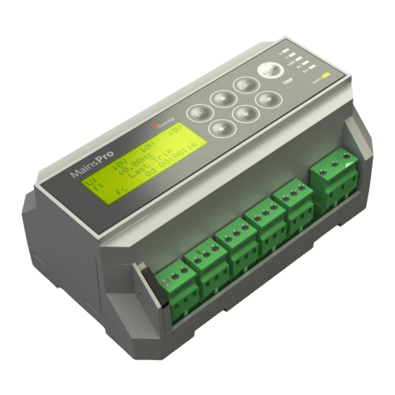
3 Installation data 3.1 Dimensions 3.2 List of terminals 3.3 MainsPro Frame 3.4 Wiring 3.5 Measurement range 3.6 Wiring examples 6 back to Table of contents 3.1 Dimensions Mains pro 1.6.1 Global Guide... -
Page 12: List Of Terminals
3.3 MainsPro Frame MainsPro Frame is a MainsPro accessory product, allowing door-mounting of the unit, direct access to the keyboard and the screen without opening the switchboard, and additional shielding (IP 55) for the front panel. The frame size is 230x180x34 mm. -
Page 13: Star" Connection
“Star” connection - MainsPro provides automatic detection of phase-ground voltage measurement. MainsPro provides over-range to 130% of the rated voltage, i.e. 300 VAC for 230 V system and 156 V for 120 V system with no change of measurement accuracy. -
Page 14: Connection With Voltage Transformers
Note: It is recommended to use “Delta” arrangement on the HV side to avoid nuisance tripping caused by phase voltage unbalance. 3.4.4 Single-phase connection MainsPro provides support for single-phase applications. Use the UA terminals to connect the measured voltage to the unit and set the setpoint System (page 52) to 1ph. -
Page 15: Power Supply
8 - 40 VDC: use the terminals + and N/- 85 - 265 VAC / 110-370 VDC: use the terminals L/+and N/- For proper connection of the power supply, see also the printed sign on the MainsPro unit: Requirements for power supply connections The unit is suitable for permanent connection to the power supply. -
Page 16: Relay Outputs Connection
3.4.6 Relay outputs connection For safety purposes, it is recommended to set all MainsPro relay outputs to inverse logic for failure trips and signaling. This means that under fault-free conditions all contacts are kept in energized position. In trip or out-of- range signaling state, the contacts de-energize. -
Page 17: Wiring Examples
120V. 3.6 Wiring examples This chapter provides examples of possible wiring of MainsPro which can be used as a preparation concept of wiring scheme. Note: ComAp bears no responsibility of functionality of the solution where these concepts are applied. - Page 18 3. Under normal conditions the contacts are closed, in case of failure the contacts open. This wiring is typically used for coil driven contactors. 6 back to Installation data Mains pro 1.6.1 Global Guide...
-
Page 19: User Interface
4 User interface 4.1 Front panel elements 4.2 Mechanical sealing 4.3 Signalization LEDs 4.4 Measurement screens 4.5 Alarm messages 6 back to Table of contents 4.1 Front panel elements Number Description 4 x 20 Alpha-numerical display Mechanical sealing indication Frequency measurement 3-phase voltage measurement Last trip indication Last trip timer... -
Page 20: Pushbuttons
Number Description TRIP LED Singalization LEDs Mechanical seal 4.1.1 Pushbuttons In the measurement screens, use the ↑ and ↓ arrow buttons to browse through the measured values as displayed on the 4x20 alphanumerical display. See the chapter Measurement screens (page 24) to get the basic orientation. -
Page 21: Reset Operation Time
4.1.3 Reset operation time 1. Enter the init screen, by pushing the ENTER and ESC at the same time. 2. Press ← to enter the Reset Oper.Time? screen: 3. Using ← and → do your selection. By selecting YES, “Operation Time" timer will be reset, and the last five events will be deleted. -
Page 22: Factory Default
4.2 Mechanical sealing MainsPro allows to mechanically prevent the setting changes by securing the mechanical seal in locked position by sealing wire. The locked position is indicated at the MainsPro side-print and on the alphanumerical display. 4.3 Signalization LEDs There are 7 LEDs for indication of MainsPro status with the meaning indicated in the table below In case of signaling different statuses by one LED, the following priorities apply, i.e. - Page 23 Meaning of signaling LEDs Color Meaning The unit has the appropriate outputs in TRIP position and the unit is sensing a fault situation TRIP The unit has the appropriate outputs in TRIP position, but the unit is flashing sensing fault-free situation. Fault reset is possible. Nothing The unit has no output in TRIP position Voltage of any phase is above threshold for 1st or 2nd stage...
-
Page 24: Measurement Screens
Color Meaning Indication of severe internal failure. Contact ComAp technical flashing support! Orange Indication of internal failure. Contact ComAp technical support! flahing Status Orange Indication of internal failure. Contact ComAp technical support! Green The unit is in operation with no internal problems. - Page 25 Functions that are configured are displayed in the appropriate order. Its status is displayed in brackets. Relay outputs 1-4 status screen: Status of the first 4 MainsPro relay outputs. Name in parenthesis marks the function assigned by the setpoints in group f(RE).
-
Page 26: Alarm Messages
Last Trip Time: time of the latest trip since MainsPro was powered-up Please note that the time information on the MainsPro unit is not measured by a calibrated RTC device and may serve for orientation purposes only. Find more in... - Page 27 Vneg Negative sequence overvoltage Vpos Positive sequence undervoltage Vavg 10 minutes floating average overvoltage Wrong phase rotation Wrong polarity of one phase External trip Start Trip 6 back to User interface Mains pro 1.6.1 Global Guide...
-
Page 28: Introduction Of Application Guide
5.1 Purpose of this manual The Application Guide serves for the designers and engineers, who process the necessary documentation and implementation procedures on the installation site, where MainsPro is installed. It contains detailed description of MainsPro functionalities its practical application. - Page 29 Small hydro power-plant Photovoltaic power plant Windmills 6 back to Introduction of Application Guide Mains pro 1.6.1 Global Guide...
-
Page 30: Important Steps Of Mainspro Utilization
6 Important Steps of MainsPro utilization This process describes a typical decisions and technical steps to follow in case of MainsPro utilization, if required by the distribution network operator (DNO). Mains pro 1.6.1 Global Guide... -
Page 31: Trip And Fault Reset
7 TRIP and Fault Reset 7.1 TRIP 7.2 Fault reset 6 back to Table of contents 7.1 TRIP TRIP may be considered as event or status of the unit (see chapters bellow). 7.1.1 TRIP event Starts in the moment of terminating the count-down of any protective function with delay, or in the moment of activation of any immediate protective function. -
Page 32: Fault Reset
7.2 Fault reset Fault reset is an event, caused by one of the following reasons: FltRes button is pressed Binary switch Fault reset is activated Automatic fault reset timer set by setpoint Auto FR Del [s] (page 53), has count down. The counter is started in the moment when all evaluated values are back within their limits. -
Page 33: Protective Features
8 Protective features The following protective functionalities, referred also by their ANSI number, are available in MainsPro unit: 8.1 ANSI 59 Overvoltage, ANSI 27 Undervoltage 8.2 Floating 10 minutes average overvoltage 8.3 ANSI 81H Overfrequency, 81L Underfrequency 8.4 ANSI 47 Voltage unbalance and angle asymmetry 8.4.1 Voltage unbalance... -
Page 34: Floating 10 Minutes Average Overvoltage
Image 8.1 Voltage hysteresis for overvoltage Image 8.2 Voltage hysteresis for undervoltage 8.2 Floating 10 minutes average overvoltage The unit calculates floating average of the measured voltage in each phase over 10 minutes interval. If any of the three phase values overreaches the setpoint Avg V>... - Page 35 Both overfrequency and underfrequency protective stages provide possibility of setting 2 levels with independent delay assigned to each level. Note: MainsPro measures frequency on the phase L1 only, therefore frequency measurement will be distorted in case that a fault occurs in this phase.
-
Page 36: Ansi 47 Voltage Unbalance And Angle Asymmetry
Image 8.4 Frequency hysteresis for underfrequency 8.4 ANSI 47 Voltage unbalance and angle asymmetry MainsPro provides 3 independent methods for evaluation of voltage symmetry failures. All of these protections are only active in case that 3-phase system is selected by the setpoint System (page 52). -
Page 37: Ansi 78 Vector Shift
Image 8.5 Decomposition of a generic 3-phase voltage to symmetrical components MainsPro provides positive and negative sequence voltage evaluation and compares the measured values with V> neg, A.V> neg [V] (page 57) V< pos, A.V< pos [V] (page 56) thresholds. In the perfectly symmetrical arrangement, negative sequence voltage is zero and positive sequence voltage equals to the measured voltage. -
Page 38: Measuring Principle
As shown in the timing diagram the voltage jumps to another value and the phase position changes. This procedure is called phase or vector surge. MainsPro continuously measures the cycles, starting each zero up ward slope. The time cycle is internally compared to the reference time. In case of vector surge the zero up ward is delayed and the device trips instantaneously. -
Page 39: Rate Of Change Of Frequency (Rocof)
8.6 81R Rate Of Change Of Frequency (ROCOF) ROCOF is another fast "Loss of Mains" protection stages provided in MainsPro. It is based on the similar principle as Vector shift, i.e. dependence of the generator speed and voltage on the load size. The variations of frequency delivered by the gen-set depend on the load fluctuations and speed of the compensated fuel inlet. -
Page 40: Application Tips
9.2 Binary switches MainsPro allows basic remote operation by means of binary signals wired from an external logic to MainsPro binary switches. The signals may be also provided remotely, e.g. through radio or GSM communicator devices. As an example for the many similar devices on the market, see the uGATE communicator below. Ask for more information about this product at protections@comap-control.com. -
Page 41: External Trip
9.2.1 External trip In case that a specific protective function is requested and this function is not supported in MainsPro, it may be provided in an external device. Wire the output of this device to Ext Trip (page 61) to allow tripping by this external device. -
Page 42: Timer
31). Use these timers for investigation of failures that were detected by MainsPro unit. Please note that MainsPro does not provide RTC clock and after each power-up of the unit, the time and date is lost. For this reason only indication of days / hh : mm is used. - Page 43 If TEST/Phase = Ub or Uc, the following protective functions are evaluated: Overvoltage and undervoltage on the appropriate terminals, with dual stage setting, including the Alt parameters possibility Note: When testing on the terminals Ub and Uc, it is always necessary, that the same measurement voltage as applied on terminals Ub or Uc is also present at the terminals Ua.
-
Page 44: Introduction Of Reference Guide
10 Introduction of Reference Guide 10.1 Purpose of this manual The Reference Guide contains library of setpoints, inputs and outputs functionalities and technical data for the purpose of detailed technical information. This information is referenced in the Installation and Operation Guide and Application Guide. -
Page 45: Technical Data
MainsPro provides the below mentioned accuracies and reaction times in case that the measured voltage on all 3 phases is within the green area on the picture below. Outside of the green area, MainsPro provides the expected performance (i.e. trips in case of voltage overreaching the green area border), but the behaviour, accuracies and reaction times may not be guaranteed. -
Page 46: Voltage Measurement
Note: Please note, that in order to fulfill the requested accuracies of the unit, it is necessary that the voltage is always present at the terminals UA with the same frequency as on the other terminals. If this is not fulfilled, even if the voltages on the measurement inputs UB and UC are within green area, they will not be evaluated accurately! 11.1.2 Voltage measurement... -
Page 47: Endurance To The Power Supply Voltage Fails
11.2.1 Endurance to the power supply voltage fails MainsPro unit withstands the power supply voltages failures of 100 ms lengths in the full range of power supply voltage on the 85 - 265 VAC / 110 - 370 VDC terminals and at the voltage .18 - 40 VDC connected to the 8 - 40 VDC terminals. - Page 48 Setpoint Setting Setpoint name Value Step Unit group Undervoltage limit 2 V<> V<< Undervoltage delay 2 V<> V<< Del 0.50 0.01 10 minutes floating average V<> Avg V> 0 (OFF) overvoltage* Overvoltage hysteresis V<> RstV>,RstV>> Undervoltage hysteresis V<> RstV<,RstV<< Voltage asymmetry limit V unb 0.0 (OFF) Negative sequence overvoltage limit...
- Page 49 In case of using "Delta" connection, the appropriate change of the setpoints is necessary. Please refer to the MainsPro Installation and Operation Guide for the wiring explanation and to the MainsPro Reference Guide for information about the setpoints adjustment.
-
Page 50: Appendix
12 Appendix 12.1 Library of Setpoints 12.2 Library of Binary switches 12.3 Relay outputs 6 back to Table of contents Mains pro 1.6.1 Global Guide... -
Page 51: Library Of Setpoints
12.1 Library of Setpoints MainsPro provides the possibility of dual setting of the protection functions setpoints. This setting may be used in case that the installation is running in exceptional conditions with different requirements for protections setting. Some groups of setpoints have their alternative setpoints identified by the same name, but with latter “A.”... -
Page 52: Group: Basic
12.1.1 Group: Basic Selection of the measurement range to adjust the HW for maximum accuracy. 230 V the unit measures 230 VAC phase-ground with max over-range 130% (300 VAC) 400 V the unit measures 400 V phase-phase with max over-range 130% (520 VAC) the unit measures 120 VAC phase-ground or on the secondary winding of the VT with 120 V max over-range 130% (156 VAC) -
Page 53: Auto Fr Del [S]
Start of the unit into the TRIP state to allow automatic delayed return to mains in case that the mains is completely lost and MainsPro unit is powered from the same mains voltage. after power-up, the unit goes immediately into the TRIP state and only after successful ENABLED fault reset its outputs are set to the fault-free state. -
Page 54: Ext
Enables or disables the functionality of the External trip binary switch. ENABLED the binary switch is enabled DISABLED the binary switch is disabled Default setting ENABLED 6 back to Library of Setpoints F.R. Enables or disables the functionality of the Fault reset binary switch and the button Fault reset. ENABLED the binary switch and the button is enabled for fault reset DISABLED... -
Page 55: Group: V <>, A
12.1.2 Group: V <>, A.V <> V>, V>>, V<, V<<, A.V>, A.V>>, A.V<, A.V<< [V] Threshold of 1st and 2nd stage overvoltage, and 1st and 2nd stage undervoltage protection, respectively. Range 1..999 V = OFF, the appropriate stage of voltage protection is not enabled V>... -
Page 56: Group: Du, A.du
RstV>,V>> [%V>] Voltage level at which the protection activates again after a trip caused by overvoltage. The TRIP status will be terminated. The setpoint is set in percentage of overvoltage threshold. In case the nominal voltage is 230 V and the overvoltage threshold is 250 V, the hysteresis limit for default setting 96 %V>... -
Page 57: Group: F <>, A.f
V> neg, A.V> neg [V] Threshold of the negative sequence overvoltage (angle asymmetry method). Range 0.0..100.0 %Un = OFF, the negative sequence overvoltage is disabled Default setting 0.0 %Un = OFF 6 back to Library of Setpoints dU del, A.dU del [s] Delay of the voltage unbalance (amplitude asymmetry) protection. -
Page 58: Group: Lom, A.lom
Rstf>,f>> [%f>] Frequency level at which the protection activates again after a trip caused by overfrequency. The TRIP status will be terminated. Range 90.0 - 100.0 %f> = OFF, the reset threshold is not activated Default setting 100.0 %f> 6 back to Library of Setpoints Rstf<,f<<... -
Page 59: Group: F(Bi)
ROCOF filt, A.ROCOF filt [-] Number of periods considered for evaluating ROCOF protection. Higher number means lower sensitivity and longer evaluation time. Lower number means increased sensitivity and shorter evaluation time. Range 1.100 Default setting 9 [-] 6 back to Library of Setpoints LOM Init Del, A. -
Page 60: Group: F(Re)
F.R. CB Fdb Not used (for the possibility if none of the defined BI is assigned) F.R. Default setting 12.1.7 Group: f(RE) f(RE1-5) Function assigned to the appropriate relay output 1 to 5. For description, see Relay outputs on page 62. CommTrpPer LOM Sig !CommTrpPer... -
Page 61: Library Of Binary Switches
In this case, the unit does not trip on any fault conditions. 12.2.5 CB Feedback Deactivation of this switch confirms opening of the circuit breaker after a trip is issued by MainsPro. If the feedback does not confirm opening of the CB, additional back-up trip BakTrpPer or BakTrpImp will be issued after adjustable time delay BakTrp Del. -
Page 62: Relay Outputs
12.3 Relay outputs The standard logic of MainsPro corresponds to the standard of protective relays and offers an option to set the logic of the relay outputs. For safety reasons there are available full set of outputs marked with an exclamation mark “!”, which remain energized in fault-free state and in case of power supply failure, the unit goes to “fault”... -
Page 63: Commtrpper
12.3.1 CommTrpPer Common trip permanent relay; closes at any failure with delay given by appropriate parameter. Relay is in fault- free state kept in open position and closes immediately in case of LOM protection (Vector shift or ROCOF), External trip, incorrect phase rotation or wrong phase polarity. Relay opens in fault free state after successful fault reset. -
Page 64: Commsigimp
12.3.6 !CommSigImp Inverse immediate impulse signaling relay; opens immediately at any failure. Relay closes after Imp Len [s] (page 53) since its opening. Any other detected fault-state during run of this timer has no effect. Fault reset has no influence on this output. 6 back to Relay outputs 12.3.7 CommSigDel Impulse signaling relay delayed;... -
Page 65: Sig
12.3.11 f Sig Immediate signaling relay – frequency; closes immediately in case of frequency failure (over or under frequency). Relay opens in case that all parameters are back within limits, but no sooner than after Basic: Imp Len from its activation. If the relay is closed during trip activation, it opens no sooner than Imp Len [s] (page since trip status activation. -
Page 66: Du Sig
12.3.16 !dU Sig Inverse immediate signaling relay – asymmetry; opens immediately in case of voltage (amplitude) unbalance, positive sequence undervoltage, negative sequence overvoltage, or failure (over or under frequency). Relay closes in case that all three methods of voltage asymmetry are in fail-free state, but no sooner than after Len [s] (page 53) from its activation. -
Page 67: Trpendimp
12.3.21 !TrpEndImp Inverse impulse at the end of the TRIP state. The output is normally deactivated during operation of the unit. The output activates at the end of the TRIP (page 31) (i.e. after successful Fault reset (page 32) is performed) for period given by the parameter Imp Len [s] (page 53). -
Page 68: Baktrpimp
12.3.26 BakTrpImp Backup trip impulse relay; closes immediately if any of the CommTrpPer (page 63) CommTrpImp (page is activated and CB Feedback doesn't deactivate within Bak Trp Del. The length of the impulse can be adjusted in Imp Len [s] (page 53).
Need help?
Do you have a question about the MainsPro and is the answer not in the manual?
Questions and answers