Table of Contents
Advertisement
Quick Links
Advertisement
Table of Contents

Related Manuals for Digital Monitoring Products XF6 Series


Summary of Contents for Digital Monitoring Products XF6 Series
- Page 1 INSTALLATION AND PROGRAMMING GUIDE XF6 Series DIGITAL MONITORING PRODUCTS, INC.
- Page 2 Contains installation and programming Instructions for use with the Model XF6 Series Fire Control Panels. When using the XF6 Series panel for any listing organization’s approved methods, refer to the Compliance Listing Guide (LT-2779). This document outlines the installation and programming requirements of all applications for which XF6 Series control panels are approved.
-
Page 3: Table Of Contents
NAC Circuits ................11 Protocol ................... 22 Zones..................12 Retry Seconds ..............22 Dry Contact Relay Outputs ..........13 Duplicate Alarms ..............22 Annunciator Outputs ............13 Send Path Information ............22 XF6 INSTALLATION AND PROGRAMMING GUIDE | DIGITAL MONITORING PRODUCTS... - Page 4 User Command Reports ........... 27 Supervisory Alarm Output ..........33 Supervisory Reports ............27 AC Fail Output ..............33 Integrator Passphrase ............27 Carbon Monoxide Alarm Output ........33 App Key .................. 27 XF6 SERIES INSTALLATION AND PROGRAMMING GUIDE | DIGITAL MONITORING PRODUCTS...
- Page 5 Stop ..................40 SET LOCKOUT CODE ......41 Set Lockout Code ............... 41 APPENDIX..........42 Diagnostics Function ............42 Using the Walk Test ............44 Walk Test ................44 Zone Types ................44 XF6 INSTALLATION AND PROGRAMMING GUIDE | DIGITAL MONITORING PRODUCTS...
-
Page 6: About The Panel
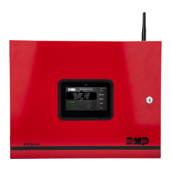
AbOUT THE PANEL The DMP XF6 Series system consists of an alarm panel with a built-in communicator, an enclosure with built-in Graphic Fire Command keypad, and a 28 VAC 130 VA transformer. A complete system can provide: • 138 or 570 programmable inputs and outputs for commercial and industrial fire alarm service •... -
Page 7: Specifications Summary
2W-BLX/2WT-BLX Addressable Smoke Detectors OUTPUTS The XF6 Series panel provides two Single Pole, Double Throw (SPDT) relay outputs which require the installation of two Model 305 relays, each rated 1 Amp at 30 VDC resistive (power limited sources only). A Model 431 Output Harness is required to use these outputs. -
Page 8: System Components
Metal Oxide Varistors and Transient Voltage Suppressors help protect against voltage surges on panel input and output circuits. Additional surge protection is available with Model 370 or 370RJ Lightning Suppressors. For more information, refer to the 370/370RJ Installation Sheet (LT-0181). Digital Monitoring Products XF6 Series Installation and Programming Guide... -
Page 9: Install The Panel
MOUNT THE ENCLOSURE The XF6 Series Series panel enclosure must be mounted using the four mounting holes shown in the image below. Mount the enclosure in a secure, dry place to protect the panel from damage from tampering or the elements. It is not necessary to remove the panel PCB when installing the enclosure. -
Page 10: Fire Command Lcd Keypad
Mount any additional modules in the panel enclosure using the standard 3-hole mounting pattern. Refer to the appropriate product guides for installation instructions. Digital Monitoring Products XF6 Series Installation and Programming Guide... -
Page 11: Wire The Panel
Caution: The XF6 Series panel requires two 12 VDC backup batteries wired in series. It cannot be powered by a single 12 VDC backup battery. -
Page 12: Power Requirements
POWER REQUIREMENTS During AC power failure, the XF6 Series panel and all connected auxiliary devices draw their power from the battery. All devices must be taken into consideration when calculating the battery standby capacity. The following table lists the XF6 Series panel power requirements. -
Page 13: Standby Battery Selection
For listed installations, batteries can be installed in a DMP Model 349, 350 or 352S enclosure and all wiring shall run through conduit. The enclosure shall be installed to the left of the XF6 Series enclosure to ensure Battery and AC wire separation. - Page 14 If the Amp Hours Required calculation is greater than any Max. Ah Available number shown on a table, then add power supply(s) to power some system devices allowing the Amp Hours Required calculation to be reduced. See the 710 Bus Splitter/Repeater Installation Guide (LT-0310). Digital Monitoring Products XF6 Series Installation and Programming Guide...
-
Page 15: Lx-Bus Expansion
Link LED (green) lights to indicate a valid receive connection from the host network. The Activity XF6 Series Panel Showing the RESET Jumper and Tamper LED (yellow) lights when connected to a 100 Mbps network and is off when connected to a 10 Mbps network connection. -
Page 16: Aux Output
The ground reference for DMP keypads, zone expansion modules, and all auxiliary devices being powered by Terminal 7. Programming (PROG) Connection A 7830F Fire Command Keypad comes pre-installed and is connected to the programming header of the XF6 Series panel. OVC LEDs The Overcurrent LED (OVC) lights red when the devices connected to the Keypad Bus and LX-Bus draw current that exceeds the panel rating. -
Page 17: Zones
Contact Color Normally Closed Violet Normally Closed Violet with white stripe Common Gray Common White with gray stripe Normally Open Orange Normally Open Orange with white stripe Model 431 Output Wiring Digital Monitoring Products XF6 Series Installation and Programming Guide... -
Page 18: Dry Contact Relay Outputs
The module includes one relay and provides three additional sockets for expansion of up to four relays. Mount the 860 inside the panel enclosure using the 3-hole pattern and plastic standoffs. Refer to the 860 Module Install Sheet (LT-0484) as needed. Relay Contact Rating is 1 Amp at 30 VDC (allows 0.35 power factor). Digital Monitoring Products XF6 Series Installation and Programming Guide... -
Page 19: Accessory Devices
263LTE-A/381-2 LTE AT&T Provides cellular communication for XF6 Series Panels. Cellular Communicator 263LTE-FN/381-2 FirstNet Provides cellular communication for XF6 Series Panels over the FirstNet network. Cellular Communicator Expansion Modules 710 Bus Splitter/Repeater Expands the number of devices and length of wire on the LX-Bus or keypad bus. - Page 20 2W-BLX Conventional Smoke A photoelectric detector that includes an addressable single point module for Detector connection to the LX-Bus of the XF6 Series panels. 2WT-BLX Conventional Smoke/ A photoelectric detector that includes an addressable single point module with a Heat Detector restorable, built-in fixed temperature thermal detector and is capable of sensing a temperature higher than 135 °F.
- Page 21 A 3 V battery-powered wireless carbon monoxide (CO) detector that provides early warning when the electrochemical sensing technology measures carbon monoxide levels in the air. The transmitter can send alarm, trouble, tamper and low battery condition messages to the alarm panel. Digital Monitoring Products XF6 Series Installation and Programming Guide...
-
Page 22: Programming
This guide provides programming information for the DMP XF6 Series panel. Before starting to program, we recommend that you read through the contents of this guide. In addition to this guide, you should also read and be familiar with the XF6 Series Compliance Listing Guide (LT-2779). Internal Programmer The panel contains all of its programming information in an on-board processor and does not require an external programmer. -
Page 23: Keypads
The panel automatically right justifies the number when you press CMD. To change a programming option that requires a NO or YES response, press the select key or touch the select area for the response not selected. Digital Monitoring Products XF6 Series Installation and Programming Guide... - Page 24 A PROGRAMMING SESSION Momentarily place the Reset jumper over both of the RESET pins to reset the panel. Enter the code 6653 (PROG) and press CMD. The keypad displays: PROGRAMMER. Digital Monitoring Products XF6 Series Installation and Programming Guide...
-
Page 25: Initialization
YES sets the panel’s programming back to factory default selections and clears all Device Setup, System Options, and Remote Options programming from the panel. Selecting YES does not clear the panel’s event memory, zone, user code information, or schedules. Digital Monitoring Products XF6 Series Installation and Programming Guide... -
Page 26: Communication
NO YES This option displays if the COMM TYPE is NET or CELL. Check-in reports are a method of supervising the panel for communication with the receiver. The default is YES. Digital Monitoring Products XF6 Series Installation and Programming Guide... -
Page 27: Fail Time
SEND PATH INFO: This option displays for each path and if YES, each panel message includes path NO YES information such as path number, communication type, and path type. Default is NO. Digital Monitoring Products XF6 Series Installation and Programming Guide... -
Page 28: Network Options
Enter the IP address of the DNS (Domain Name System) used by the panel to resolve 192.168.0.1 domain names into IP addresses. The default address is 192.168.0.1. On systems with hardwired network connection, the DNS address can be changed even if the panel has DHCP enabled. Digital Monitoring Products XF6 Series Installation and Programming Guide... -
Page 29: Device Setup
This section allows you to select a device type for the selected device number. FIRE ‑ A 7830F Fire Command Keypad or 630F Remote Annunciator. See Fire Device Remote Programming in the XF6 Series Compliance Guide (LT-2779) for instructions on how to allow remote panel programming. -
Page 30: Remote Options
Zone reports send changes in the status of active zones. Includes the zone number, name, type, the action (alarm, trouble, bypass, etc.), and user number (if applicable). If performing a Walk Test, Zone Verify and Zone Fail messages are sent for each zone. Digital Monitoring Products XF6 Series Installation and Programming Guide... -
Page 31: User Command Reports
Press CMD to view all of the integrator report options. Choose YES to enable zone, user code, or supervisory message reports. All reports default to YES. Digital Monitoring Products XF6 Series Installation and Programming Guide... -
Page 32: Zone Reports
IP address programmed in Network Options. To enter a new App Key, press any select key or area and enter any combination of 8 digits. Press CMD. Digital Monitoring Products XF6 Series Installation and Programming Guide... -
Page 33: System Options
Hawaii* Rome, Paris, Berlin Midway Island, Samoa Fiji, Marshall Island, Wellington, Auckland, Kwajalein, Kamchatka *Arizona, Hawaii, American Samoa, Guam, Puerto Rico, and the Virgin Islands do not observe daylight savings time. Digital Monitoring Products XF6 Series Installation and Programming Guide... -
Page 34: Latch Supervisory Zones
Status List and is sent to the central station receiver. Select YES to enable jamming messages to display in the Status List. Select NO to disable jamming messages. Default is YES. Digital Monitoring Products XF6 Series Installation and Programming Guide... -
Page 35: Wireless Encryption
(9 PM to 9 AM). Select MIN (minimum) to annunciate only Fire and Fire Verify zones during daytime hours (9 AM to 9 PM). Default is ANY. Digital Monitoring Products XF6 Series Installation and Programming Guide... -
Page 36: Bell Options
Defines Bell Action for Supervisory Type zones. The default is N. Carbon Monoxide (CO) CO TYPE: Defines Bell Action for Carbon Monoxide (CO) Type Zones. The default is set at 4. Digital Monitoring Products XF6 Series Installation and Programming Guide... -
Page 37: Output Options
The output is turned off when the device responds to polling or is removed from programming in the system. Enter 0 (zero) to disable this output and LX-Bus™ device fail reporting to the receiver. If any addressed device is unsupervised, this output cannot be used. Digital Monitoring Products XF6 Series Installation and Programming Guide... -
Page 38: Sensor Reset Output
This output turns on any time a Carbon Monoxide Zone (CO) is placed in alarm. The output is turned off using Sensor Reset option while no additional CO type zones are in alarm. Digital Monitoring Products XF6 Series Installation and Programming Guide... -
Page 39: Output Information
Selecting YES allows Real-Time Status reports of a hardwire device, such as Output ON, OFF, PULSE, or TEMPORAL to be sent using PC Log reports. Selecting NO disables Real- Time Status for this output device. Default is NO. Digital Monitoring Products XF6 Series Installation and Programming Guide... -
Page 40: Output Groups
An output group may be assigned as one of the output numbers in another output group. See the XF6 Users Guide (LT-2792) Output Group section for additional information. Output groups 1 to 20 are available for installation applications such as special lighting, etc. Digital Monitoring Products XF6 Series Installation and Programming Guide... -
Page 41: Zone Information
The panel contains 4 default zone types for use in configuring the system. These zone types provide the most commonly selected functions for their applications. All zone types can be customized by changing the options listed below. Digital Monitoring Products XF6 Series Installation and Programming Guide... -
Page 42: Fire Bell Output
SERIAL#: XXXXXXXX Enter the eight-digit serial number found on the DMP wireless device. Already In Use displays when the serial number is already programmed for another zone. The programmed zone number displays. Digital Monitoring Products XF6 Series Installation and Programming Guide... -
Page 43: Contact
MOMENTARY - The output is turned on only once for one second. FOLLOW - The output is turned on and remains on while the zone is in an off normal, or bad condition. When the zone restores, the output is turned off. Digital Monitoring Products XF6 Series Installation and Programming Guide... -
Page 44: Swinger Bypass
If NO, this zone will operate as a standard fire type zone and a sensor reset is required before the zone will return to normal. Default is NO. Digital Monitoring Products XF6 Series Installation and Programming Guide... -
Page 45: Stop
When the panel is powered up after an AC power failure, any zone transitions are not recognized for 60 seconds. Normal zone processing resumes at the end of the 60 seconds. Digital Monitoring Products XF6 Series Installation and Programming Guide... -
Page 46: Set Lockout Code
Lost Lockout Codes require the panel to be sent back to DMP for repair. You may cancel a Lockout Code by entering 00000 at the Set Lockout Code command. Lockout Code restriction Do not set a Lockout Code higher than 65535. Digital Monitoring Products XF6 Series Installation and Programming Guide... -
Page 47: Appendix
LX-Bus. To correct the problem, check your zone programming and zone expansion module addressing. Extra - A device is installed on the LX-Bus but none of its zones are programmed into the system. Digital Monitoring Products XF6 Series Installation and Programming Guide... - Page 48 NO ACK RECEIVED Network Results: Successful Display Failure Display LINK OK LINK ERROR DHCP OK DHCP ERROR GATEWAY FOUND NO GATEWAY DEST FOUND NO DESTINATION COMM PATH GOOD NOT CONNECTED NO ACK RECEIVED Digital Monitoring Products XF6 Series Installation and Programming Guide...
-
Page 49: Using The Walk Test
Sensor Reset occurs. The System Test End message is sent to the receiver along with Verify and Fail messages for each zone under test. Faulted zones then display on the keypad. Digital Monitoring Products XF6 Series Installation and Programming Guide... -
Page 50: Trip Counter For Dmp Wireless Check-In Test (Wls)
On - Fire zone alarm and Bell Output or Fire Bell Output is ON. Off - Alarm Silence. On - CO zone alarm and Bell Ouput are ON. Off - Using Sensor Reset option while no additional CO type zones are in alarm. Digital Monitoring Products XF6 Series Installation and Programming Guide... -
Page 51: Wireless Check-In And Supervision Definitions
This output turns on any time a Carbon Monoxide Zone (CO) is placed in alarm. The output is turned off using Sensor Reset option while no additional CO type zones are in alarm. Digital Monitoring Products XF6 Series Installation and Programming Guide... -
Page 52: Common Keypad Messages
Verify the receiver is properly connected to wireless receiver. the panel. Verify the correct House Code is WIRELESS TROUBLE programmed in System Options. Satisfy the The wireless receiver’s tamper may be faulted. front and/or rear tamper. Digital Monitoring Products XF6 Series Installation and Programming Guide... -
Page 53: Fcc Information
Increase the separation between the equipment and receiver. • Connect the equipment into an outlet on a circuit different from that to which the receiver is connected. • Consult the dealer or an experienced radio/TV technician for help. Digital Monitoring Products XF6 Series Installation and Programming Guide... - Page 54 Digital Monitoring Products XF6 Series Installation and Programming Guide...
- Page 55 A C C E S S N E T W O R K manufactured using U.S. and global 2500 North Partnership Boulevard components in Springfield, MO. Springfield, Missouri 65803-8877 © 2021 Digital Monitoring Products, Inc. 888.436.7832 | DMP.com LT-2777 23462 1.01...
Need help?
Do you have a question about the XF6 Series and is the answer not in the manual?
Questions and answers