
Related Manuals for Digital Monitoring Products XT30INT


Summary of Contents for Digital Monitoring Products XT30INT
- Page 1 INTERNATIONAL INSTALLATION GUIDE XT30INT Control Panel DIGITAL MONITORING PRODUCTS, INC. Digital Monitoring Products | XT Series International Programming Guide...
- Page 2 MODEL XT30INT CONTROL PANEL INSTALLATION GUIDE © 2024 Digital Monitoring Products, Inc. Information furnished by DMP is believed to be accurate and reliable. This information is subject to change without notice.
-
Page 3: Table Of Contents
Connect to Cell ..............13 Standby Battery Calculations .............8 Troubleshooting ........14 Step 4: Wiring the TERMINALS ....9 Common LCD Keypad Displays........14 Wire for Bell Output - Terminals 5 and 6 ......9 Digital Monitoring Products | XT Series International Programming Guide... - Page 4 Product Specifications Summary .... 15 Power Supply ............... 15 Communication ..............15 Panel Zones................15 Keypads/Expansion ............15 Number of Zones ..............15 Outputs .................. 15 International Certifications ...... 16 Intertek (ETL) Listed............16 XT30 International Programming Guide | Digital Monitoring Products...
-
Page 5: Get Started
Whenever you see a caution note, make sure you completely read and understand its information. Failing to follow the caution note can cause damage to the equipment or improper operation of one or more components in the system. Digital Monitoring Products | XT Series International Programming Guide... -
Page 6: System Components
This transient protection provides additional resistance to electrical surges such as lighting. Accessory Devices CELLULAR COMMUNICATOR CARDS 263HINT HSPA + Cellular Allows you to connect the XT30INT to any compatible HSPA+/SMS network. Communicator ZONE AND OUTPUT EXPANSION MODULES 710 Bus Splitter/Repeater Increases keypad wiring distance to 2500 feet. -
Page 7: Wiring Diagram
100 mA at 10.2 - 13.9 VDC Terminal 11 3.3k Ohm - DMP Model 309 Figure 1: System Wiring Diagram For complete programming descriptions, refer to the XT30 International Programming Guide (LT-0981INT). Digital Monitoring Products | XT Series International Programming Guide... -
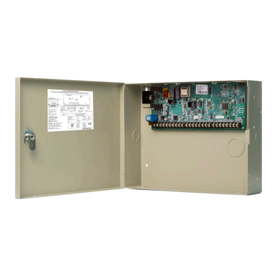
Page 8: Step 1: Mount The Enclosure
Phone Line Accessory Ethernet Modules Reset Programming Dual 4.4 cm and 6.3 cm Conduit Knockouts * 349AINT Optional Knockout Tamper Switch for 349AINT Attack Resistant Enclosure Battery Shelf Figure 4: Optional 349AINT Enclosure XT30 International Programming Guide | Digital Monitoring Products... -
Page 9: Step 2: Mount The Keypads
When voltage is too low, the devices cannot operate properly. For additional information, refer to the 710 Installation Sheet (LT-0310) and the LX-Bus/Keypad Bus Wiring Application Note (LT-2031). Digital Monitoring Products | XT Series International Programming Guide... -
Page 10: Step 3: Wire The Power Supply
Figure 4: Wiring Multiple Batteries Caution: Use sealed lead-acid batteries only. Use 12 VDC sealed lead-acid rechargeable battery. Gel cell batteries cannot be used with the XT30INT Control Panel. Earth Ground Terminal 4 of the panel must be connected to earth ground using 14 gauge or larger wire to provide proper transient suppression. -
Page 11: Discharge/Recharge
The total is then multiplied by the total number of standby hours required to arrive at the total Ampere-hours required. Digital Monitoring Products | XT Series International Programming Guide... -
Page 12: Standby Battery Calculations
Total Standby______mA x number of Standby Hours needed ______ = ________mA-hours Total Alarm ______mA + ________mA-hours Total ________mA-hours * Based on 10% of active zones in alarm condition. X .001 = ________Amp-hrs Required XT30 International Programming Guide | Digital Monitoring Products... -
Page 13: Step 4: Wiring The Terminals
Wire for Keypad Data Bus - Terminals 7, 8, 9, & 10 Terminals 7, 8, 9, and 10 of the panel are designated as the keypad data bus. In addition to keypads, the XT30INT allows the connection of any combination of zone expansion modules, Glassbreak Detectors, and PIRs to the keypad bus up to the maximum of eight devices. -
Page 14: Overcurrent Ovc Led
User Menu. Terminal 10 is the ground reference for terminal 11. Wire Burglary Zones - Terminals 12-24 On XT30INT panels, terminals 12 to 24 are the nine burglary zones. For programming purposes, the zone numbers are 1 to 9. The zone configurations on terminals 12 to 24 are described below. -
Page 15: Keyswitch Arming Zone
A resettable 2-wire Class B powered zone is provided on terminals 25 (positive) and 26 (negative) of the panel. For programming purposes, the zone number is 10 on the XT30INT. The zone uses a Model 309, 3.3k ohm EOL resistor (provided with the panel) and has an operating range of 8.8 to 13.9 VDC. -
Page 16: Connect To Public Telephone Network
XT30INT Panel Supervision LOAD OUTPUTS PHONE LINE ETHERNET Momentarily place OVC LED the Reset jumper Power RESET over both of the XMIT RESET pins to PROG reset the panel. Figure 8: Panel RESET Header XT30 International Programming Guide | Digital Monitoring Products... -
Page 17: Update Panel Software On Flash Load Jumper
Update Panel Software on Flash LOAD Jumper The XT30INT Control Panel software can be updated using the panel’s programming header. To update the panel with a new software version, complete the following steps at the protected premise. Place a jumper across the RESET header and remove the yellow and green wires from keypad bus terminals 8 and 9. -
Page 18: Troubleshooting
TROUBLESHOOTING This section provides troubleshooting information for use when installing or servicing an XT30INT/XT50INT system. PROBLEM POSSIBLE CAUSE POSSIBLE SOLUTIONS Keypad displays SYSTEM TROUBLE RESET Jumper is installed Remove the RESET reset jumper Open or short on the green data wire to the... -
Page 19: Product Specifications Summary
Outputs ▶ The XT30INT Control Panels provide four open collector outputs rated for 50 mA each. A Model 300 Output Harness is required. The open collector outputs provide the ground connection for a positive voltage source. Digital Monitoring Products | XT Series International Programming Guide... -
Page 20: International Certifications
INTERNATIONAL CERTIFICATIONS Intertek (ETL) Listed EN 50130-4:2011+A1:2014 Alarm systems. Electromagnetic compatibility. Product family standard: Immunity requirements for components of fire, intruder, hold up, CCTV, access control and social alarm systems. EN 50130-5:2011 Alarm systems. Environmental test methods. EN 50131-1:2006+A1:2009 Alarm systems. Intrusion and hold-up systems. System requirements. EN 50131-3:2009 Alarm systems.
Need help?
Do you have a question about the XT30INT and is the answer not in the manual?
Questions and answers