
Related Manuals for Digital Monitoring Products COMMAND PROCESSOR XR500


Summary of Contents for Digital Monitoring Products COMMAND PROCESSOR XR500
- Page 1 INST ALLA TION GUIDE XR500/XR500N ACCESS CONTROL COMMAND PROCESSOR™ PANEL LT-0681 (1/04) © 2004 Digital Monitoring Products, Inc.
- Page 2 This booklet is available from the U.S. Government Printing OfÞ ce, Washington D.C. 20402 Stock No. 004-000-00345-4 © 2004 Digital Monitoring Products, Inc. Information furnished by DMP is believed to be accurate and reliable. This information is subject to change without notice.
-
Page 3: Table Of Contents
Terminal 9 - GREEN ..................12 Terminal 10 - BLACK ..................12 J8 Programming Connection ................. 12 OVC LED..................... 12 Smoke and Glassbreak Detector Output Terminals 11 and 12 ..................12 Current Rating..................... 12 Digital Monitoring Products XR500/XR500N Installation Guide... - Page 4 Control Outside of Protected Area ..............20 20.4 Police Station Phone Numbers ..............20 20.5 Bypass Reports.................... 20 20.6 System Maintenance ..................20 20.7 UL Listed Receivers..................20 20.8 Power Supply Supervision ................20 Digital Monitoring Products XR500/XR500N Installation Guide...
- Page 5 Mercantile Safe and Vault (XR500N only)............24 26.5 Grade A Bell ....................24 26.6 Bank Safe and Vault (XR500N only) .............. 24 UL 294 SpeciÞ cations 27.1 Panel Designation ..................24 27.2 Compatible Devices ..................24 Digital Monitoring Products XR500/XR500N Installation Guide...
- Page 6 Cellular Backup Installation for Derived Channel Burglary ....... 31 32.5 Rothenbuhler 5110 High Security Bell Wiring ..........32 32.6 LX-Bus™ Module Connection ................ 33 32.7 Model 860 Relay Module Connection ............. 34 OPERATING INSTRUCTIONS MODEL XR500/XR500N PANELS Digital Monitoring Products XR500/XR500N Installation Guide...
-
Page 7: Product Speciþ Cations
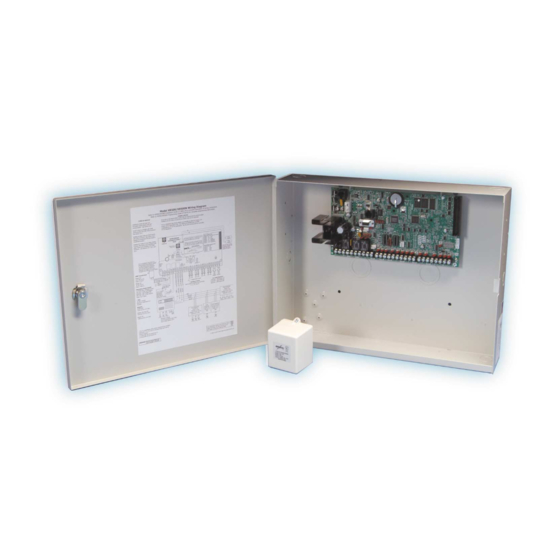
Gray (G) Construction: Door: 16-gauge cold-rolled steel. Back and Sides: 18-gauge cold-rolled steel Model 350 Enclosure Dimensions: 17.5” W x 13.5” H x 3.5” D Color: Gray (G), or Red (R) Construction: 18-gauge cold-rolled steel Digital Monitoring Products XR500/XR500N Installation Guide... -
Page 8: Panel Features
The LX-Bus™ also supports the Model 717 Graphic Annunciator Module. Each 717 module supplies 20 switched ground outputs that follow the state of their assigned zones. Refer to the 717 Installation Guide (LT-0235) for more information. Digital Monitoring Products XR500/XR500N Installation Guide... -
Page 9: Central Station Communication
You can also connect auxiliary devices to the panel’s output relays to expand the basic system’s control capability. Combined current requirements of additional modules may require an auxiliary power supply. Refer to section 6.8 in this guide when calculating power requirements. Digital Monitoring Products XR500/XR500N Installation Guide... -
Page 10: Wiring Diagram
TO THESE CIRCUITS UNLESS APPROVED BY THE LOCAL AUTHORITY HAVING 1.9 Amp with 56 VA transformer, 1.0 Amp Max for Auxiliary Power and JURISDICTION (AHJ). 1.5 Amp Max for Bell Figure 1: XR500/XR500N Wiring Diagram Digital Monitoring Products XR500/XR500N Installation Guide... -
Page 11: Lightning Protection
Single-zone, addressable module conventional smoke/smoke heat detectors that connect to the LX-Bus. SLRLX Includes remote maintenance reporting, drift compensation, and multi-criteria detection. * These devices have not been investigated by UL and shall not be used in UL installations. Digital Monitoring Products XR500/XR500N Installation Guide... -
Page 12: Notiþ Cation Appliances
806-6 Bell, 6 inch MB-G6-12 806-10 Bell, 10 inch MB-G10-12 Strobe, 15/75 candela RSS-121575W-F Strobe, w/retroÞ t plate RSSP-121575W-F Horn Strobe, 15/75 candela NS-121575W-F Sync Module, Single circuit, SM-12/24-R Sync Module, Dual circuit DM-12/24-R Digital Monitoring Products XR500/XR500N Installation Guide... -
Page 13: Installation
The DMP 711, 711E, 712-8, 714, 715, 716, and 717 modules are each contained in molded plastic housings with removable covers. The base provides you with mounting holes for installing the unit to a wall, switch plate, or other surface. Digital Monitoring Products XR500/XR500N Installation Guide... -
Page 14: Connecting Lx-Bus And Keypad Bus Devices
56 VA) wire-in transformer when required by the Authority Having Jurisdiction (AHJ). The transformer must be connected to an unswitched 120 VAC 60 Hz electrical outlet with at least 350mA of available current. Never share the transformer output with any other equipment. Digital Monitoring Products XR500/XR500N Installation Guide... -
Page 15: Secondary Power Supply
Security Command® keypads, zone expansion modules, smoke detector output, and any other auxiliary devices used in the system for the total current required. The total is then multiplied by the number of standby hours required to calculate the total ampere-hours required. Digital Monitoring Products XR500/XR500N Installation Guide... - Page 16 Total Alarm ______mA Total Standby______mA x number of Standby Hours needed ______ = ________mA-hours Total Alarm ______mA + ________mA-hours Total ________mA-hours X .001 = ________Amp-hrs Required Refer to section 6.9 for standby battery selection. Digital Monitoring Products XR500/XR500N Installation Guide...
-
Page 17: Standby Battery Selection
Note: If the Amp Hours Required calculation is greater than any Max. Ah Available number shown on a table, then add power supply(s) to power some system devices allowing the Amp Hours Required calculation to be reduced. Digital Monitoring Products XR500/XR500N Installation Guide... -
Page 18: Bell Output
The Output current from terminal 11 is shared with terminals 7, 25, and 27. The total current draw of all devices powered from the panel must be included with terminal 11 calculations and must not exceed the maximum output rating. Digital Monitoring Products XR500/XR500N Installation Guide... -
Page 19: Protection Zones
Note: Do not mix detectors from different manufacturers on the same zone. Caution: Performing a Sensor Reset momentarily drops power to the devices on Zones 9 and 10. The panel views these zones (9 and 10) as “Open” while the power is absent. Digital Monitoring Products XR500/XR500N Installation Guide... -
Page 20: Compatible 2-Wire Smoke Detector Chart
9 & 10 DH400 715-16 715, 715-8, System Sensor 2W-B, 2WT-B 8.5-35 9 & 10 715-16 715, 715-8, System Sensor DH100P, DH100LP 8.5-35 9 & 10 715-16, 725 Figure 5: Compatible 2-Wire Smoke Detectors Digital Monitoring Products XR500/XR500N Installation Guide... -
Page 21: Dry Contact Relay Outputs
7. The module includes one relay and provides three additional sockets for expansion of up to four relays. Mount the 860 inside the panel enclosure using the 3-hole pattern and plastic standoffs. Refer to the 860 Module Install Sheet (LT-0484) as needed. Relay Contact Rating: 1 Amp at 30 VDC Digital Monitoring Products XR500/XR500N Installation Guide... -
Page 22: J23 6-Pin Header
461 Adaptor Card and One Interface Card Multiple Interface Cards LX-Bus Zones Numbers LX-Bus Zones Numbers 500-599 1 (A) 500-599 LX-Bus 2 (B) 600-699 Enabled 3 (C) 700-799 4 (D) 800-899 5 (E) 900-999 Digital Monitoring Products XR500/XR500N Installation Guide... -
Page 23: Lx-Bus Leds
The telephone company may make changes in its facilities, equipment, operations or procedures that could affect the operation of the equipment. If this happens the telephone company will provide advance notice in order for you to make necessary modifi cations to maintain uninterrupted service. Digital Monitoring Products XR500/XR500N Installation Guide... -
Page 24: Description
RJ31X wiring is backwards. Rewire so dial tone is coming IN on 4 and 5. If you still have trouble with the phone line, you may need to replace the RJ cord. If the dial tone is still not present, swap out the RJ31X phone block. Digital Monitoring Products XR500/XR500N Installation Guide... -
Page 25: Reset And Tamper Headers
If the enclosure is opened or removed while one or more of the system areas are armed, a panel tamper alarm is indicated. If all areas are disarmed, a panel tamper trouble is indicated. Digital Monitoring Products XR500/XR500N Installation Guide... -
Page 26: Universal Ul Burglary Speciþ Cations
20.8 Power Supply Supervision For commercial burglary applications the power supply for all local bells shall be under 24-hour protection. Refer to section 6 in this document. Digital Monitoring Products XR500/XR500N Installation Guide... -
Page 27: Ownership
The maximum entry delay used must not be more than 45 seconds. See the XR500/XR500N Programming Guide (LT-0679). 22.5 Exit Delay The maximum exit delay used must not be more than 60 seconds. See the XR500/XR500N Programming Guide (LT-0679). 22.6 Weekly Test The product should be tested weekly. Digital Monitoring Products XR500/XR500N Installation Guide... -
Page 28: Opening/Closing Reports
The Test Time option must be programmed so that the XR500/XR500N sends a report once every 24 hours. See the XR500/XR500N Programming Guide (LT-0679). 24.4 Closing Wait The Closing Wait option must be programmed YES. See the XR500/XR500N Programming Guide (LT-0679). Digital Monitoring Products XR500/XR500N Installation Guide... -
Page 29: System Trouble Display
200 seconds, an attack resistant enclosure is not required. See sections 3.2, 3.2.1, and 3.3 of the XR500/XR500N Programming Guide (LT-0679). To provide High Line Encrypted security, install an XR500 panel and an iCOM-E™ Encrypted Internet Alarm Router. Digital Monitoring Products XR500/XR500N Installation Guide... -
Page 30: Grade A Mercantile
PDR-5455 ProxPro® II Reader Long range reader with sounder MX-5375 Maxi-Prox™ Reader Long range reader compatible with 1351 Prox Pass * This device has not been investigated by UL and shall not be used in UL installations. Digital Monitoring Products XR500/XR500N Installation Guide... -
Page 31: Universal Ul And Nfpa Fire Alarm Speciþ Cations
The Video option must be selected as NO when any Þ re protection is connected to the XR500/XR500N. See the XR500/XR500N Programming Guide (LT-0679). 28.13 UL Listed Receivers Use the DMP SCS-1/SCS-1R (SDLC), Sur-Gard SG-HLR2-DG (CID), FBII CP220PB (CID), and Osborne-Hoffman Quick-Alert (CID) receivers. Digital Monitoring Products XR500/XR500N Installation Guide... -
Page 32: Ul 864 Nfpa 72 (Chapter 9) Speciþ Cations
• RETRY TIME must be programmed as 1 • SUB CODE must be programmed as YES • FAIL TIME must be programmed as 1 • CHECKIN must be programmed as 1 • NET TRBL must be programmed as YES Digital Monitoring Products XR500/XR500N Installation Guide... -
Page 33: Ul 985 Nfpa 72 (Chapter 2) Speciþ Cations
31.1 Bell Output DeÞ nition The Model XR500/XR500N panel Bell Output must be programmed to operate steady on burglary alarms and pulsed, temporal, or California School Code on Þ re alarms. See the XR500/XR500N Programming Guide (LT-0679). Digital Monitoring Products XR500/XR500N Installation Guide... -
Page 34: Wiring Diagrams
WIRING DIAGRAMS Wiring Diagrams 32.1 Multiple NotiÞ cation Circuit Modules Digital Monitoring Products XR500/XR500N Installation Guide... -
Page 35: Multiple Notiþ Cation Circuit Modules For Zoned Annunciation
Power from the XR500 panel. Zone 2 Notification 59mA through its Terminal 3 Alarm Circuit Module To additional notification Input and 26mA from its Terminal 1 DMP Model 865 circuit modules. Aux Power Input. 26mA @ 12 VDC Digital Monitoring Products XR500/XR500N Installation Guide... -
Page 36: Dual Style D Zone Module Installation
S = Supervised Circuit Fault A Zone A Zone A Aux Power Zone B Heat Detectors, manual pull stations, or any other UL Zone B Listed shorting device. Unlimited number of units. Fault B Digital Monitoring Products XR500/XR500N Installation Guide... -
Page 37: Cellular Backup Installation For Derived Channel Burglary
WIRING DIAGRAMS 32.4 Cellular Backup Installation for Derived Channel Burglary Digital Monitoring Products XR500/XR500N Installation Guide... -
Page 38: Rothenbuhler 5110 High Security Bell Wiring
WIRING DIAGRAMS 32.5 Rothenbuhler 5110 High Security Bell Wiring Digital Monitoring Products XR500/XR500N Installation Guide... -
Page 39: Lx-Bus™ Module Connection
Typical Relay 4 Normally Closed Common Normally Open Model 716 Output Expander Module 7m at 12 VDC Optional LED wiring 50mA at 50 VDC resistive Model 717 Graphic Annunciator Module 10m at 12 VDC Digital Monitoring Products XR500/XR500N Installation Guide... -
Page 40: Model 860 Relay Module Connection
32.7 Model 860 Relay Module Connection Digital Monitoring Products XR500/XR500N Installation Guide... - Page 41 Digital Monitoring Products XR500/XR500N Installation Guide...
-
Page 42: Operating Instructions Model Xr500/Xr500N Panels
The operating instructions above should be attached to the front, or framed and located adjacent to, the panel or a Security Command keypad with an alphanumeric display. LT-0681 (1/04) © 2004 Digital Monitoring Products, Inc. 800-641-4282 INTRU SIO N • FIR E • AC CE SS • NET WOR KS www.dmp.com...
Need help?
Do you have a question about the COMMAND PROCESSOR XR500 and is the answer not in the manual?
Questions and answers