Table of Contents
Advertisement
Quick Links
Advertisement
Table of Contents

Related Manuals for Digital Monitoring Products XT Series


Summary of Contents for Digital Monitoring Products XT Series
- Page 1 INSTALLATION GUIDE DIGITAL MONITORING PRODUCTS, INC.
- Page 2 MODEL XT30/XT50 SERIES CONTROL PANEL INSTALLATION GUIDE © 2021 Digital Monitoring Products, Inc. Information furnished by DMP is believed to be accurate and reliable. This information is subject to change without notice...
-
Page 3: Table Of Contents
CONTENTS Get Started ............1 Terminal 8 - YEL..................9 Terminal 9 - GRN ..................9 How to Read This Guide ............1 Terminal 10 - BLK ..................9 Caution Notes ....................1 Keypad Bus LEDs ..................9 Compliance Instructions ................1 Programming (PROG) Connection ..........9 What's Included ..............1 Keypad Addressing ................9 What You'll Need ..............1 Overcurrent OVC LED ................9... - Page 4 Step 7: Install Wireless Keypads .... 16 Specifications ..........26 Mount the Keypads ............. 16 Power Supply ...............26 Associate Wireless Keypads ..........16 Enclosure ................26 LCD Wireless Keypad ................16 Communication ..............26 Wireless Graphics Touchscreen Keypad ........16 Keypads/Expansion ............26 Power/Armed LED ................16 Panel Zones................26 Number of Zones ..............27 Listed Compliance Specifications ...
-
Page 5: Get Started
Your kit or package may include more devices and accessories than what is shown below. XT Panel Documentation Enclosure Lock and Key Hardware Pack (ordered separately) What You'll Need ▶ Drill ▶ Pliers ▶ Wire connectors XT Series Installation Guide | Digital Monitoring Products... -
Page 6: System Components
Allows you to control the panel from various remote locations. Connect up to seven keypads. keypads 9060, 9063 Wireless Keypads. 9800 Series Wireless Graphic Allows you to control the panel from various remote locations. Connect up to seven keypads. Touchscreen keypads 9862 Wireless Keypads. XT Series Installation Guide | Digital Monitoring Products... - Page 7 Fixed temperature heat detector. 1183-135R Heat Detector Fixed temperature and rate-of-rise heat detector. 1184 Carbon Monoxide Detector Carbon Monoxide Detector. * These devices have not been investigated and shall not be used in listed installations. XT Series Installation Guide | Digital Monitoring Products...
-
Page 8: Xt30/Xt50 Wiring Diagram
For listed applications the maximum current from a combination of bell output and auxillary output is 1.6 amps. SECONDARY POWER SUPPLY 1.2 Amps maximum charging current. Use only 12 VDC rechargeable batteries. Replace every 3 to 5 years. Figure 1: System Wiring Diagram XT Series Installation Guide | Digital Monitoring Products... -
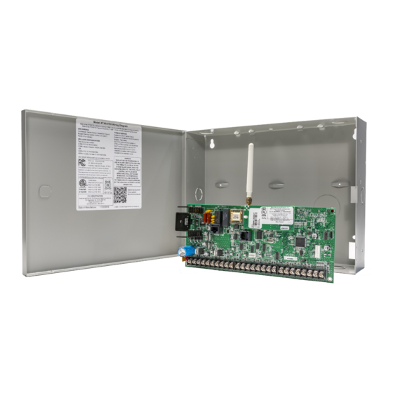
Page 9: Step 1: Mount The Enclosure
Front and Rear Tamper Switches for 350A Attack Resistant Enclosure Tamper Mounting Holes (Upper and Lower) Lid Mounting Holes (4) Battery Shelf 349A Optional Knockout Figure 3: Optional 341 Enclosure (left), Optional 349A Enclosure (right) XT Series Installation Guide | Digital Monitoring Products... -
Page 10: Step 2: Mount The Keypads
When voltage is too low, the devices cannot operate properly. For additional information refer to the 710 Installation Sheet (LT-0310) and or the LX-Bus/Keypad Bus Wiring Application Note (LT-2031). XT Series Installation Guide | Digital Monitoring Products... -
Page 11: Step 3: Wire The Power Supply
DMP recommends connecting to a metal cold water pipe or ground rod only. Do not connect to electrical conduit or a telephone company ground. Replacement Period DMP recommends replacing the battery every 3 to 5 years under normal use. XT Series Installation Guide | Digital Monitoring Products... -
Page 12: Discharge/Recharge
The total is then multiplied by the total number of standby hours required to arrive at the total Amperehours required. XT30/XT50 Standby Battery Calculations For complete battery calculations, see the Battery Calculator. XT Series Installation Guide | Digital Monitoring Products... -
Page 13: Step 5: Wire The Terminals
9 and 10 as shown in Figure 5. When the OVC LED lights Red, the Keypad bus/auxiliary power (terminal 7) and the PROG header BELL shut down. Figure 5: OVC LED Location XT Series Installation Guide | Digital Monitoring Products... -
Page 14: Wire Smoke And Glassbreak Detector Output - Terminal 11
2.2 - 2.9 VDC Short 0 - 2.1 VDC Applies to zones 1-9 on XT Series panels with version 193 firmware and higher Zone Response Time A condition must be present on a zone for 500 milliseconds before it is detected by the panel. Ensure detection devices used on the protection zones are rated for use with this delay. -
Page 15: Wire Powered Zone For 2-Wire Smoke Detectors - Terminals 25 And 26
Plastic standoffs are provided with the module for ease of installation. A 4-wire harness is also provided that connects the Model 860 to the panel. Relay Contact Rating: 1 Amp at 30 VDC XT Series Installation Guide | Digital Monitoring Products... -
Page 16: Connect To Public Telephone Network
The two LEDs, located on the left side of the ETHERNET Connector, indicate network operation. The top, Link LED is a steady green light when an ethernet cable is connected. The bottom, Activity LED flashes yellow to indicate messages are being received or transmitted. XT Series Installation Guide | Digital Monitoring Products... -
Page 17: Reset The Panel
Figure 8: Panel Showing the RESET Header Update Panel Software on Flash LOAD Jumper The XT Series panel software can be updated via the panel’s Programming (PROG) header. To update the panel with a new software version, complete the following steps at the protected premise:... -
Page 18: Model 401 Usb Flash Module
The 763 Wi-Fi Module is compatible with all DMP XT30/XT50 OUTPUTS Series control panels with Level L hardware and Version 124 or higher firmware. RESET Link LED Z10+ Z10- Included 3ft cable Figure 10: 763 to XT30/XT50 Series XT Series Installation Guide | Digital Monitoring Products... -
Page 19: Wire For On-Board 1100 Series Wireless Antenna Connection
Under normal operation, the yellow LED will flash at every trip of every wireless transmitter and occasionally when the transmitters perform their periodic check-in. It is not unusual for this LED to stay off for many minutes at a time when no transmitters are communicating. XT Series Installation Guide | Digital Monitoring Products... -
Page 20: Step 7: Install Wireless Keypads
When successful XMIT communication has been established, the Power/Armed LED turns Blue on PROG Graphics keypads or Green on LCD keypads. Figure 12: Transmit and Receive LEDs XT Series Installation Guide | Digital Monitoring Products... -
Page 21: Listed Compliance Specifications
For listed applications, the maximum auxiliary current is 400 mA, and the maximum bell current is 500 mA. Cross Zoning Each zone must have the capability of protecting the common area individually. App Key The Remote Option App Key has not been evaluated for use in listed applications. XT Series Installation Guide | Digital Monitoring Products... -
Page 22: Compliance
The maximum exit delay used must not be more than 60 seconds. Test Frequency The Test Frequency option must be programmed to send a report once every 24 hours. Automatic Bell Test This option must be programmed as YES. XT Series Installation Guide | Digital Monitoring Products... -
Page 23: Central Station Burglar Alarm Units - Ansi/Ul 1610
When using the Model 860 Relay Output, a fire and non-fire device must not share a relay. Test Frequency The Test Frequency option must be programmed to send a report at least once every 30 days. XT Series Installation Guide | Digital Monitoring Products... -
Page 24: California State Fire Marshal Specifications
California State Fire Marshal Specifications Bell Output Definition The bell output of the Model XT30/XT50 must be programmed to operate steady on burglary alarms and temporal on fire alarms. XT Series Installation Guide | Digital Monitoring Products... -
Page 25: False Alarm Reduction Programmable Options - Ansi/Sia Cp-01-2010
Caution: A call waiting cancel programmed on a non-call waiting telephone line, would prevent communication to the central station. Entry Delay Only use Entry Delay 1. Do not use Entry Delay 2. See the XT30/XT50 Programming Guide (LT-0981). XT Series Installation Guide | Digital Monitoring Products... -
Page 26: Local Bell
7060, 7063, 7070, 7073, 7160, 7163, 7170, or 7173 Thinline™ Keypads ▶ 7060A, 7063A, 7070A, or 7073A Aqualite™ Keypads ▶ 7360 or 7363 Thinline™ Icon Keypads ▶ 7872 or 7873 Graphic Touchscreen Keypads XT Series Installation Guide | Digital Monitoring Products... -
Page 27: Troubleshooting
Verify your communication type, account number, and The panel has attempted to communicate with the central TRANSMIT FAIL phone number. Make sure the telephone line is connected station multiple times and has not succeeded. and working properly. XT Series Installation Guide | Digital Monitoring Products... -
Page 28: Wiring Diagrams
WIRING DIAGRAMS Multiple Indicating Circuit Modules Installation XT Series Installation Guide | Digital Monitoring Products... -
Page 29: System Sensor 2-Wire Smoke Detectors
OUT + TEST & MAINTENANCE MODULE OUT - IN + IN - 3.3K Z10+ 470 Ohm or Z10- (2) 1k in Parallel Orange Yellow 3.9K EOL SYSTEM SENSOR 2WTA-B or 2WTR-B SMOKE DETECTORS XT Series Installation Guide | Digital Monitoring Products... -
Page 30: Specifications
Single-zone PIR and glassbreak detectors Panel Zones ▶ Nine 1k or 2.2K ohm EOL burglary zones: zones 1 to 9 ▶ One 3.3k ohm EOL Class B powered fire zone with reset capability: zone 10 XT Series Installation Guide | Digital Monitoring Products... -
Page 31: Number Of Zones
▶ FCC Part 68 Registration ID CCKAL00BXT50 ETL Listed ANSI/SIA CP-01 False Alarm Reduction ANSI/UL 1023 Household Burglar ANSI/UL 985 Household Fire Warning ANSI/UL 1610 Central Station Burgla ANSI/UL 1635 Digital Burglar XT Series Installation Guide | Digital Monitoring Products... -
Page 32: Fcc Information
FCC Information This equipment has been tested and found to comply with the limits for a Class B digital device, pursuant to part 15 of the FCC Rules. These limits are designed to provide reasonable protection against harmful interference in a residential installation. This equipment generates, uses and can radiate radio frequency energy and, if not installed and used in accordance with the instructions, may cause harmful interference to radio communications.
Need help?
Do you have a question about the XT Series and is the answer not in the manual?
Questions and answers