Table of Contents
Advertisement
Quick Links
Advertisement
Table of Contents

Related Manuals for Digital Monitoring Products INTERNATIONAL Series


Summary of Contents for Digital Monitoring Products INTERNATIONAL Series
- Page 1 INTERNATIONAL SERIES INSTALLATION GUIDE DIGITAL MONITORING PRODUCTS, INC.
- Page 2 This booklet is available from the U.S. Government Printing Office, Washington D.C. 20402 Stock No. 004-000-00345-4 © 2023 Digital Monitoring Products, Inc. Information furnished by DMP is believed to be accurate and reliable. This information is subject to change without notice.
-
Page 3: Table Of Contents
ANNUNCIATOR OUTPUTS ...... 17 SECONDARY POWER SUPPLY ....9 DESCRIPTION ................ 17 BATTERY TERMINALS 3 AND 4 ........9 MODEL 860INT RELAY MODULE ........17 EARTH GROUND (GND) ............ 9 BATTERY ONLY START ............9 XR150INT/XR550INT SERIES INSTALLATION GUIDE | DIGITAL MONITORING PRODUCTS... - Page 4 CONNECTING THE ANTENNA ........22 WI-FI CONNECTION ....... 23 763 MODULE TO EXP HEADER ........23 STATUS LED ................23 MOUNTING THE 763 ............23 INTERNATIONAL CERTIFICATIONS ..24 DOCUMENTATION ........24 ..................... 24 XR150INT/XR550INT SERIES INSTALLATION GUIDE | DIGITAL MONITORING PRODUCTS...
-
Page 5: Product Specifications Summary
Model 305 relays, each rated 1 Amp at 30 VDC resistive (power limited sources only). A Model 431 Output Harness is required to use these outputs. The panels also provide four open collector outputs rated for 50mA each. The open collector outputs provide ground XR150INT/XR550INT SERIES INSTALLATION GUIDE | DIGITAL MONITORING PRODUCTS... -
Page 6: Enclosure Specifications
25 programmable Model 716 Output Expansion Modules to each LX-Bus. These modules can provide an additional 500 or 100 programmable SPDT relays. The panels provide Output Schedules for programming the 716 to perform a variety of annunciation and control XR150INT/XR550INT SERIES INSTALLATION GUIDE | DIGITAL MONITORING PRODUCTS... -
Page 7: Monitoring Center Communication
Always ground the panel before applying power to any devices: The panel must be properly grounded before connecting any devices or applying power to the panel. Proper grounding protects against Electrostatic Discharge (ESD) that can damage system components. XR150INT/XR550INT SERIES INSTALLATION GUIDE | DIGITAL MONITORING PRODUCTS... -
Page 8: System Components
Metal Oxide Varistors and Transient Voltage Suppressors help protect against voltage surges on panel input and output circuits. Additional surge protection is available by installing the Model 270 Network Transient Suppression Module. XR150INT/XR550INT SERIES INSTALLATION GUIDE | DIGITAL MONITORING PRODUCTS... -
Page 9: Accessory Devices
EOL resistor for external contact. Provides Disarm/Disable functionality. 1122INT PIR Motion Detector Provides motion detection with pet immunity. 1128INT Wireless Glassbreak Provides fully-supervised, low current shock and glassbreak detection coverage up to 20 ft. Detector XR150INT/XR550INT SERIES INSTALLATION GUIDE | DIGITAL MONITORING PRODUCTS... -
Page 10: Compliance Instructions
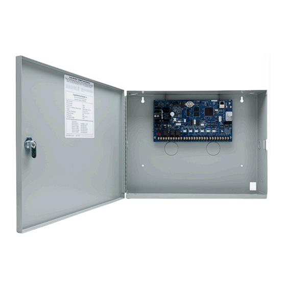
PROG BELL Z10+ Z10- Dual 1 3/4" and 1 3/8" Conduit Knockouts * 350A Optional Knockout Tamper Switch for 350A Attack Resistant Enclosure Battery Shelf holds up to three 7 Ah Batteries XR150INT/XR550INT SERIES INSTALLATION GUIDE | DIGITAL MONITORING PRODUCTS... -
Page 11: Mounting Keypads And Zone Expansion Modules
The DMP 712-8INT module may be mounted inside the panel enclosure using the 3-hole pattern and plastic standoffs. XR150INT/XR550INT SERIES INSTALLATION GUIDE | DIGITAL MONITORING PRODUCTS... -
Page 12: The Dmp 714-8Int, And 714-16Int Modules Are Contained In A Dmp Model 340 Enclosure
LED turns from Red to Green. Wireless keypads are assigned to the first open device position in Device Setup automatically XR550INT Showing Reset and Transmit/Receive based upon the order in which they are detected XR150INT/XR550INT SERIES INSTALLATION GUIDE | DIGITAL MONITORING PRODUCTS... -
Page 13: Primary Power Supply
The leads need a momentary short only. Once the relay has pulled in, the battery voltage holds it in that condition. If the XR150/XR550 International Series panel is powered up with an AC transformer, the battery cutoff relay is pulled in automatically. -
Page 14: Discharge/Recharge
Battery Supervision The XR150/XR550 International Series tests the battery when AC power is present. The test is done every three minutes and lasts for five seconds. During the test, the panel places a load on the battery; if the battery voltage falls below 11.9VDC a low battery is detected. - Page 15 Total Alarm *Based on 10% of active zones in alarm ______ Total Standby______mA x number of Standby Hours ______ = _______mA-hours needed ______mA +_______mA-hours Total Alarm Total _______mA-hours X .001 = _______Amp-hrs Required XR150INT/XR550INT SERIES INSTALLATION GUIDE | DIGITAL MONITORING PRODUCTS...
-
Page 16: Standby Battery Selection
If the Amp Hours Required calculation is greater than any Max. Ah Available number shown on a table, then add power supply(s) to power some system devices allowing the Amp Hours Required calculation to be reduced. XR150INT/XR550INT SERIES INSTALLATION GUIDE | DIGITAL MONITORING PRODUCTS... -
Page 17: Bell Output
LX-Bus(es) and Keypad bus are shut down. • • The OVC LED located to the left of the 893A connector indicates overcurrent for the Keypad Bus (Terminals 7-10 and PROG header), XBUS, and LX500-LX700. XR150INT/XR550INT SERIES INSTALLATION GUIDE | DIGITAL MONITORING PRODUCTS... -
Page 18: Smoke And Glassbreak Detector Output
Normally Closed Normally Open Combination Normally Open and Normally Closed Zone Response Time A condition must be present on a zone for 500 milliseconds before it is detected by the XR150INT/XR550INT Series XR150INT/XR550INT SERIES INSTALLATION GUIDE | DIGITAL MONITORING PRODUCTS... -
Page 19: Keyswitch Arming Zone
• System Ready • Late to Close • Panic Alarm • Ready • Armed • Disarmed • Burglary • Phone Trouble • Device Fail • Sensor Rest • Closing Wait Contact Rating XR150INT/XR550INT SERIES INSTALLATION GUIDE | DIGITAL MONITORING PRODUCTS... -
Page 20: Model 431 Output Harness Wiring
• Orange • Output 1 common • Gray • Output 1 normally closed • Violet The relay contacts must be connected to devices located within the same room as the XR150INT/XR550INT Series panel. XR150INT/XR550INT SERIES INSTALLATION GUIDE | DIGITAL MONITORING PRODUCTS... -
Page 21: Annunciator Outputs
• • LX600, provides zones/outputs 600-699 (XR550INT only) • • LX700, provides zones/outputs 700-799 (XR550INT only) • • LX800, provides zones/outputs 800-899 (XR550INT only) • • LX900, provides zones/outputs 900-999 (XR550INT only) LX-Bus Headers and LEDs XR150INT/XR550INT SERIES INSTALLATION GUIDE | DIGITAL MONITORING PRODUCTS... -
Page 22: Ax-Bus (Xr550)
The two LEDs, located above each LX-Bus/AX-Bus header, indicate data transmission and receipt. The left LED flashes green to indicate the panel is transmitting LX-Bus/AX-Bus data. The right LED flashes yellow to indicate the panel is receiving LX-Bus/AX-Bus data. XR150INT/XR550INT SERIES INSTALLATION GUIDE | DIGITAL MONITORING PRODUCTS... -
Page 23: Ovc Leds
Network Transient Suppression The Model 270 Transient Suppression Module provides surge suppression from the Ethernet network for the protection of DMP Panels. Refer to the Model 270 Installation Sheet (LT-1316) for complete information. XR150INT/XR550INT SERIES INSTALLATION GUIDE | DIGITAL MONITORING PRODUCTS... -
Page 24: Phone Line Rj Connector
Rewire so dial tone is coming IN on 4 and 5. If you still have trouble with the phone line, you may need to replace the RJ cord. If the dial tone is still not present, swap out the RJ31X phone block. XR150INT/XR550INT SERIES INSTALLATION GUIDE | DIGITAL MONITORING PRODUCTS... -
Page 25: Reset And Tamper Headers
If the enclosure is opened or removed while one or more of the system areas are armed, a panel tamper alarm is indicated. If all areas are disarmed, a panel tamper trouble is indicated. XR150INT/XR550INT SERIES INSTALLATION GUIDE | DIGITAL MONITORING PRODUCTS... -
Page 26: Cellular Modules
SMA connectore when the coax enters the enclosure via conduit. Antenna Connector Connector Washers Coax Cable from Cellular Module XR150INT/XR550INT International Panel Connector Stando Model 381-2 Coax Cable from the 263 module Cellular Module Installation XR150INT/XR550INT SERIES INSTALLATION GUIDE | DIGITAL MONITORING PRODUCTS... -
Page 27: Wi-Fi Connection
Connect the included cable to the 763 6-pin header. Hold the transmitter base in its mounting location. Place the supplied screw into the mounting hole location to secure the housing to the surface. XR150INT/XR550INT SERIES INSTALLATION GUIDE | DIGITAL MONITORING PRODUCTS... -
Page 28: International Certifications
A C C E S S N E T W O R K manufactured using U.S. and global 2500 North Partnership Boulevard components in Springfield, MO. Springfield, Missouri 65803-8877 © 2021 Digital Monitoring Products, Inc. 888.436.7832 | DMP.com LT-1233 21404 1.01...
Need help?
Do you have a question about the INTERNATIONAL Series and is the answer not in the manual?
Questions and answers