Table of Contents
Advertisement
Quick Links
p u b l i c
UG-2023-15
EVAL-IHW25N140R5L
2 kW induction heating evaluation board with reverse conducting R5L
IGBT
About this document
Scope and purpose
The induction heating, quasi-resonant board EVAL-IHW25N140R5L features the new 1400 V reverse conducting
R5L IGBT. It is specifically designed for induction heating and resonant switching applications [1]. This user
guide describes the functionality and key features of the evaluation board with R5L IGBT in combination with
the 1ED4417xx family of Infineon EiceDRIVER™ [2] gate driver ICs.
Intended audience
Engineers who want to learn how to use Infineon's reverse conducting IGBTs in combination with
•
EiceDRIVER™ 1ED4417xx family
Design engineers who design circuits with Infineon EiceDRIVER™ and/or RC IGBTs and who develop
•
power electronic devices
Evaluation board
This board is to be used during the design-in process for evaluating and measuring characteristic curves, and
for checking datasheet specifications.
Note:
PCB and auxiliary circuits are NOT optimized for final customer design.
User guide
www.infineon.com
Please read the sections "Important notice" and "Warnings" at the end of this document
Revision 1.0
2023-08-04
Advertisement
Table of Contents

Related Manuals for Infineon EVAL-IHW25N140R5L


Summary of Contents for Infineon EVAL-IHW25N140R5L
-
Page 1: About This Document
R5L IGBT in combination with the 1ED4417xx family of Infineon EiceDRIVER™ [2] gate driver ICs. Intended audience Engineers who want to learn how to use Infineon’s reverse conducting IGBTs in combination with • EiceDRIVER™ 1ED4417xx family Design engineers who design circuits with Infineon EiceDRIVER™... -
Page 2: Important Notice
Boards provided by Infineon Technologies. The design of the Evaluation Boards and Reference Boards has been tested by Infineon Technologies only as described in this document. The design is not qualified in terms of safety requirements, manufacturing and operation over the entire operating temperature range or lifetime. -
Page 3: Safety Precautions
EVAL-IHW25N140R5L 2kW induction heating evaluation board with reverse conducting R5L IGBT Safety precautions Safety precautions Note: Please note the following warnings regarding the hazards associated with development systems Table 1 Safety precautions Warning: The DC link potential of this board is up to 1000 VDC. When measuring voltage waveforms by oscilloscope, high voltage differential probes must be used. -
Page 4: Table Of Contents
EVAL-IHW25N140R5L 2kW induction heating evaluation board with reverse conducting R5L IGBT Table of contents Table of contents About this document ........................1 Important notice ..........................2 Safety precautions .......................... 3 Table of contents ..........................4 The board at a glance ...................... -
Page 5: The Board At A Glance
EVAL-IHW25N140R5L was designed based on the environmental conditions described in this document. The design was tested as described in this document, but is not qualified in terms of manufacturing, lifetime, or over the full range of ambient operating conditions. The boards provided by Infineon are not subject to full production tests. -
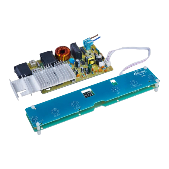
Page 6: Scope Of Supply
The board at a glance Scope of supply EVAL-IHW25N140R5L contains two printed circuit boards. The main board contains all power electronic parts of the inverter circuit while the second board is the user interface that allows control and changing of inverter operating conditions. -
Page 7: Block Diagram
EVAL-IHW25N140R5L 2kW induction heating evaluation board with reverse conducting R5L IGBT The board at a glance Block diagram Figure 2 Block diagram of the evaluation board Figure 2 shows a top-level overview of the induction heating board’s building blocks. Detailed overview of a... -
Page 8: System And Functional Description
EVAL-IHW25N140R5L 2kW induction heating evaluation board with reverse conducting R5L IGBT System and functional description System and functional description Getting started Board setup To set up the board for evaluation, follow these steps: 1. Connect the user interface board to CN1 (position of the first pin should be closer to the mounting hole). -
Page 9: Functional Blocks And Control Description
EVAL-IHW25N140R5L 2kW induction heating evaluation board with reverse conducting R5L IGBT System and functional description Functional blocks and control description Figure 3 Quasi-resonant board: building blocks Figure 4 User interface board: control functions explanation User guide Revision 1.0... -
Page 10: Basic Operation Of The Board: An Example
EVAL-IHW25N140R5L 2kW induction heating evaluation board with reverse conducting R5L IGBT System and functional description Basic operation of the board: an example 1. Press the Power button. Two dashes “- -” will flash on the 7-segment display indicating that all auxiliary parts of induction board are turned on. -
Page 11: System Design
EVAL-IHW25N140R5L 2kW induction heating evaluation board with reverse conducting R5L IGBT System design System design Schematics Complete schematics are available in a PDF format on the evaluation board’s webpage under the Design Support section. Login credentials are required to download this material. -
Page 12: Layout
EVAL-IHW25N140R5L 2kW induction heating evaluation board with reverse conducting R5L IGBT System design Figure 6 Schematic of the user interface board Layout Table 2 Printed circuit board layout parameters Parameter Value Board dimensions: Inverter board... - Page 13 EVAL-IHW25N140R5L 2kW induction heating evaluation board with reverse conducting R5L IGBT System design Figure 7 Layout of the quasi-resonant power board Figure 8 Layout of the user interface board User guide Revision 1.0 2023-08-04...
-
Page 14: Bill Of Material
EVAL-IHW25N140R5L 2kW induction heating evaluation board with reverse conducting R5L IGBT System design Bill of material Complete bill of material (BOM) is available on the evaluation board’s webpage under the Design Support section. Login credentials are required to download this material. -
Page 15: System Performance
System performance System performance Test points The EVAL-IHW25N140R5L induction heating board is suitable for real application use case testing. To properly acquire data from the evaluation test please follow the recommendations for connecting probes to the board. Figure 9 All three terminals of the IGBT have exposed test points ( ) for easy voltage measurement. - Page 16 EVAL-IHW25N140R5L 2kW induction heating evaluation board with reverse conducting R5L IGBT System performance The current of the power switch can be measured using a Rogowski coil that is hooked around the collector pin Figure 10...
-
Page 17: Test Results
Figure 11 Recommended mounting for the thermocouple Test results In this section the typical operation and characteristic waveforms of the EVAL-IHW25N140R5L induction board are described. In Figures 12 to 15, the waveforms are color-coded as follows: Yellow waveform: IGBT current (I •... - Page 18 EVAL-IHW25N140R5L 2kW induction heating evaluation board with reverse conducting R5L IGBT System performance Figure 12 Load detection pulse A typical operation of this resonant inverter is the so-called soft switching commutation. This technique aims to mitigate switching losses by ensuring that the voltage or current across the power device transitions through zero before the device is turned on or off.
- Page 19 EVAL-IHW25N140R5L 2kW induction heating evaluation board with reverse conducting R5L IGBT System performance Figure 14 Hard switching operation at power level 3 Induction cookers work across a wide range of output power. When using a typical design approach in soft...
- Page 20 EVAL-IHW25N140R5L 2kW induction heating evaluation board with reverse conducting R5L IGBT System performance Figure 15 Burst mode operation at power level 3 Table 5 The result of thermal tests is shown in . The temperature of the IGBT gets lower with increasing output power.
-
Page 21: Appendices
EVAL-IHW25N140R5L 2kW induction heating evaluation board with reverse conducting R5L IGBT Appendices Appendices Resonant load details Resonant load properties with respect to frequency 4000 3500 3000 2500 2000 1500 1000 Frequency(kHz) Resistance without vessel... -
Page 22: References
EVAL-IHW25N140R5L 2kW induction heating evaluation board with reverse conducting R5L IGBT Appendices References [1] The 650 V Reverse Conducting R6 family for induction heating and resonant applications [2] EiceDRIVER™ webpage: https://www.infineon.com/cms/en/product/power/gate-driver- ics/1ed44171n01b/ User guide Revision 1.0 2023-08-04... -
Page 23: Revision History
EVAL-IHW25N140R5L 2kW induction heating evaluation board with reverse conducting R5L IGBT Revision history Revision history Document Date Description of changes revision 04 August 2023 First version User guide Revision 1.0 2023-08-04... -
Page 24: Disclaimer
For information on the types in question please contact your nearest Published by Infineon Technologies office. Except as otherwise explicitly approved by Infineon Infineon Technologies AG Technologies in a written document signed by 81726 Munich, Germany authorized...
Need help?
Do you have a question about the EVAL-IHW25N140R5L and is the answer not in the manual?
Questions and answers