Table of Contents
Advertisement
Quick Links
UG-2021-42
EVAL-IKA15N65ET6 User Guide
About this document
Scope and purpose
This user guide provides an overview of the evaluation board EVAL-IKA15N65ET6 including main features, key
data, pin assignments, and mechanical dimensions.
EVAL-IKA15N65ET6 was developed to support customers in their first steps designing applications for
permanent magnet synchronous motors (PMSM) or brushless DC machines e.g. pumps, fans, washing
machines, general purposes drives, and power tools up to 1.2 kW.
The board is fully equipped with all assembly groups required to achieve sensor-less or sensor-based, field
oriented control (FOC). To this end, various Infineon product families have been utilized, such as
TRENCHSTOP
5 IGBT in power factor correction (PFC) circuit together with a Rapid 1 silicon power diode,
TM
TRENCHSTOP
IGBT6 in inverter stage, iMOTION™ driver to control both PFC and inverter stage, XENSIV
TM
high-precision coreless current sensor to sense the current, and
Intended audience
This user guide is intended for all technical specialists who have a good knowledge of motor control and high-
power electronic converters. The board must only be used under laboratory conditions.
Evaluation board
The board is to be used during the design-in process for evaluating and measuring characteristic curves, and
for checking datasheet specifications.
Note:
Printed Circuit Board and auxiliary circuits are NOT optimized for final customer design.
www.infineon.com
Please read the sections "Important notice" and "Warnings" at the end of this document
CoolSET
in auxiliary power supplies.
TM
—
TM
V1.1
2022-09-21
Advertisement
Table of Contents

Related Manuals for Infineon EVAL-IKA15N65ET6


Summary of Contents for Infineon EVAL-IKA15N65ET6
-
Page 1: About This Document
About this document Scope and purpose This user guide provides an overview of the evaluation board EVAL-IKA15N65ET6 including main features, key data, pin assignments, and mechanical dimensions. EVAL-IKA15N65ET6 was developed to support customers in their first steps designing applications for permanent magnet synchronous motors (PMSM) or brushless DC machines e.g. -
Page 2: Important Notice
Boards provided by Infineon Technologies. The design of the Evaluation Boards and Reference Boards has been tested by Infineon Technologies only as described in this document. The design is not qualified in terms of safety requirements, manufacturing and operation over the entire operating temperature range or lifetime. -
Page 3: Safety Precautions
EVAL-IKA15N65ET6 User Guide Safety precautions Safety precautions Note: Please note the following warnings regarding the hazards associated with development systems. Safety precautions Table 1 Warning: The DC link potential of this board is up to 1000 VDC. When measuring voltage waveforms by oscilloscope, high voltage differential probes must be used. -
Page 4: Table Of Contents
PFC stage ............................... 20 Current sensing ............................. 21 Power stage ............................21 Auxiliary power supply .......................... 22 PCB layout of EVAL-IKA15N65ET6 ......................23 Bill of material ........................25 System performance - evaluation results ................. 33 Auxiliary power supply test ........................33 PFC test .............................. -
Page 5: The Board At A Glance
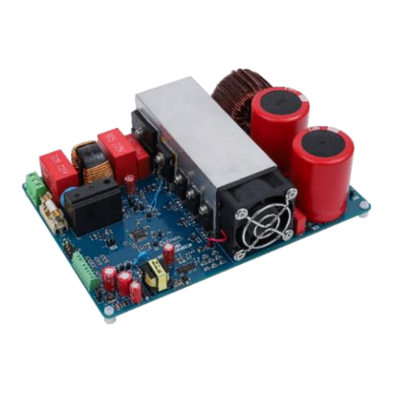
(PC) software tools is required to set up the system and to control and fine-tune its performance to match users’ needs (see Chapter 3). EVAL-IKA15N65ET6 is available through regular Infineon distribution partners and from Infineon’s website. The features of this board are described in the “Main features” section of Chapter 2. The other chapters provide information on how to copy, modify, and qualify the design for production according to customers’... - Page 6 PFC stage Motor inverter and phase connector iMOTION link interface Functional groups of the EVAL-IKA15N65ET6 evaluation board, top side Figure 1 Figure 2 shows the functional groups on the bottom side of the board. Functional groups, bottom side: TLI4971 hall sensors...
-
Page 7: Block Diagram
EVAL-IKA15N65ET6 User Guide The board at a glance Block diagram Figure 3 shows the block diagram of EVAL-IKA15N65ET6. Block diagram of EVAL-IKA15N65ET6 Figure 3 V1.1 2022-09-21... -
Page 8: Main Features
800 V CoolMOS P7 super-junction MOSFETs in a DSO-12 package Board specifications of EVAL-IKA15N65ET6 Table 1 lists the key specifications of the evaluation board EVAL-IKA15N65ET6. EVAL-IKA15N65ET6 board specifications Table 1 Parameters Values Conditions/comments... -
Page 9: Pin Assignment
Ambient temperature 25°C Tested at ambient temperature Pin assignment The EVAL-IKA15N65ET6 evaluation board provides an AC input connector and a 3-phase output for connecting the motor. Table 2 lists the details of the AC input connector J1. J1- AC line connector... - Page 10 EVAL-IKA15N65ET6 User Guide Main features Line AC line input Neutral AC neutral input Earth Earth ground Table 3 lists the details of the motor side connector J2. J2- Motor side connector Table 3 Details Connected to motor phase W Connected to motor phase V Connected to motor phase U V1.1...
-
Page 11: Getting Started
Getting started Getting started To run a motor system with the EVAL-IKA15N65ET6 evaluation board, the iMOTION™ PC software tools— MCEDesigner and MCEWizard—are required to set up the system and to control and fine-tune the system’s performance to meet user requirements. This chapter provides information on how to set up the system and get started with the EVAL-IKA15N65ET6 evaluation board. -
Page 12: Imotion™ Development And Software Tools
EVAL-IKA15N65ET6 User Guide Getting started System connections using EVAL-IKA15N65ET6 Figure 4 iMOTION™ development and software tools The iMOTION™ development tools—MCEDesigner and MCEWizard—can be downloaded from Infineon’s iMOTION website (http://www.infineon.com/imotion-software). All available tools and software versions are listed there. The iMOTION Link debug probe is an essential tool for configuring, parameterizing, and programming the IMD112T-6F040 that is not included in the scope of delivery. - Page 13 EVAL-IKA15N65ET6 User Guide Getting started Click OK and return to the Welcome Page. Select Customized Design for Expert User. Click on Next to answer questions concerning hardware design and user test motor specifications. Welcome page of MCEWizard Figure 5 The iMOTION™ PC software tools enable users to easily test their motors. Users should be familiar with system level parameters that are related to the motor used.
- Page 14 EVAL-IKA15N65ET6 User Guide Getting started Question 16 Target DC bus voltage 380 V initialization Question 24 Controller supply voltage Question 46 Maximum DC bus voltage 500 V Question 50 DC bus sensing high resistor 2000 kΩ Depends on the board...
-
Page 15: Mcedesigner Setup Overview
Double-click the shortcut to open the MCEDesigner. Open the MCEDesigner default configuration file (.irc) for IMD112T smart driver (IMD112T_V1.03.03.irc) included in the firmware zip folder that was downloaded from Infineon’s website. The controller’s power supply should be selected either 3.3 V or 5 V in MCEWizard Then select the available COM port in Performance >... - Page 16 Choose the relevant .ldf file and text file. Click Start to program the .ldf and .txt files. The .ldf file can be downloaded from Infineon’s website. The .txt file was created by the MCEWizard as described in Chapter 3.2.1. The programming window is shown in Figure 8.
-
Page 17: Firmware Version Update
If users want to test the board with the latest firmware, they can download the latest version from Infineon’s website. Then they need to open the latest MCEDesigner configuration file (.irc file) and re-program the latest firmware file (.ldf file). -
Page 18: Hall Sensor Tli4971 Programming
GUI software tool are required to program the sensor. This tool can be downloaded from Infineon’s website (link). The current sensor programmer board (link) is essential to program the EEPROM memory. Figure 10 shows the Hall sensor EEPROM programming window. For programming details, please download the application note and datasheet for the programming guide and the user manual from Infineon’s... - Page 19 IKA15N65ET6 board, as shown in Figure 11. The programmer board has three channels for connecting three sensors at the same time. For EVAL-IKA15N65ET6, users can use two channels to connect the two Hall sensors, as shown in Figure 11, and then select sensor 1 or sensor 2 to program the two TLI4971 sensors in the programming pop-up window.
-
Page 20: Hardware Description
PFC stage The EVAL-IKA15N65ET6 board contains a boost PFC stage to reduce the reactive power and total harmonic distortion (THD) in the grid. The PFC function on the evaluation board is performed by TRENCHSTOP™ 5 WR6 IGBT IKWH30N65WR6 combined with the silicon power diode IDW30E65D1. -
Page 21: Current Sensing
TLI4971 is a high-precision sensor for AC and DC measurements with analog interface and two fast overcurrent detection outputs. Infineon's well-established and robust monolithic Hall technology enables accurate and highly linear measurement of currents with full scale up to ±120 A. Negative effects such as saturation and hysteresis that are common in open loop sensors using flux concentration techniques are thus avoided. -
Page 22: Auxiliary Power Supply
Figure 13 shows the schematic diagram of the auxiliary power supply of the EVAL-IKA15N65ET6 board. The circuit includes ICE5GR4780AG that is used to generate 15 V and 6 V through the fixed-frequency flyback topology from the DC bus. -
Page 23: Pcb Layout Of Eval-Ika15N65Et6
35 µm copper, and dimensions of 178 mm × 125 mm. The PCB board thickness is 1.6 mm. Users can contact Infineon’s technical support team for more detailed information and the latest design files. Figure 14 illustrates the top layer routing of the evaluation board. - Page 24 EVAL-IKA15N65ET6 User Guide Hardware description Bottom layer routing of the EVAL-IKA15N65ET6 evaluation board Figure 15 V1.1 2022-09-21...
-
Page 25: Bill Of Material
EVAL-IKA15N65ET6 User Guide Bill of material Bill of material Table 5 provides the complete bill of material of EVAL-IKA15N65ET6. Bill of materials Table 5 No. Qty Part description Designator Part number Manufacturer 25A GLASS PASSIVATED GBJ2506-F Diodes Incorporated BRIDGE RECTIFIER... - Page 26 EVAL-IKA15N65ET6 User Guide Bill of material 0603(1608) / SMD / -, CAP C37, C42, / CERA / 1nF / 25V / 5% / C0G (EIA) / NP0 / -55°C to 125°C / 0603(1608) / SMD CAP / CERA / 1uF / 25V /...
- Page 27 EVAL-IKA15N65ET6 User Guide Bill of material CAP / ELCO / 220uF / 16V / 860010373010 Wurth Elektronik 20% / Aluminium electrolytic / -40°C to 85°C / 2.50mm C X 0.50mm W 6.30mm Dia X 12.50mm H / THT / -...
- Page 28 EVAL-IKA15N65ET6 User Guide Bill of material Surface Mount Ultrafast US1M-E3/61T Vishay Rectifier 1.0A/1000V Super-fast Recovery RF071MM2STR ROHM Diode, VR 200 V, IF 1 A Semiconductors High Voltage Surface- SS2H10-E3/52T Vishay Mount Schottky Rectifier, VRRM 100V Surface-Mount Schottky BYS10-45-E3/TR3 Vishay Barrier Rectifier, VRRM...
- Page 29 EVAL-IKA15N65ET6 User Guide Bill of material IND / STD / 2.2uH / 2.5A / 744773022 Wurth Elektronik 20% / -40°C to 125°C / 71mR / SMD / Inductor, SMD; 2-Leads, 4.50 mm L X 4 mm W X 3.50 mm H...
- Page 30 EVAL-IKA15N65ET6 User Guide Bill of material RES / STD / 100R / 100mW R19, R28, RC0603FR-07100RL Yageo / 1% / 100ppm/K / -55°C to 155°C / 0603 / SMD / - RES / STD / 1.2k / 100mW ERA3ARB122V Panasonic / 0.1% / 10ppm/K / -55°C...
- Page 31 EVAL-IKA15N65ET6 User Guide Bill of material RES / STD / 68k / 250mW / CRCW120668K0FK Vishay 1% / 100ppm/K / -55°C to 155°C / 1206 / SMD / - RES / STD / 510k / 100mW CRCW0603510KFK Vishay / 1% / 100ppm/K / -55°C to 155°C / 0603 / SMD / -...
- Page 32 EVAL-IKA15N65ET6 User Guide Bill of material script engine for application control customization, Thin-film- SOI-technology with negative transient robustness, Built-in temperature sensor High-precision coreless U2, U4 TLI4971-A025T5-E0001 Infineon current sensor Technologies Gate drivers LOW SIDE 1ED44175N01B Infineon DRIVERS Technologies Fixed-frequency 700...
-
Page 33: System Performance - Evaluation Results
EVAL-IKA15N65ET6 User Guide System performance - evaluation results System performance - evaluation results This chapter describes the test bench results of different functional blocks. Equipment IR camera: FLIR310A • Scope: Tek3054 • Motor: GK6063-6AC31 • Power meter: Tektronix PA1000 •... - Page 34 • Note: This section provides the experimental data of the EVAL-IKA15N65ET6 board under typical operating conditions. Different load, switching frequency (f ), and input voltage conditions are included. It should be highlighted that all possible test conditions are not covered in this user guide However, it should be expected that when 16 kHz is selected as the inverter’s switching...
- Page 35 EVAL-IKA15N65ET6 User Guide System performance - evaluation results AR01: Inverter IGBT case temperature AR02: PFC IGBT case temperature AR03: PFC choke temperature 165 V input and half load test Figure 17 V1.1 2022-09-21...
- Page 36 EVAL-IKA15N65ET6 User Guide System performance - evaluation results AR01: Inverter IGBT case temperature AR02: PFC IGBT case temperature AR03: PFC choke temperature 165 V input and full load test Figure 18 V1.1 2022-09-21...
- Page 37 EVAL-IKA15N65ET6 User Guide System performance - evaluation results = 6 kHz = 16 kHz AR01: Inverter IGBT case temperature AR02: PFC IGBT case temperature AR03: Rectifier bridge AR04: PFC choke AC line voltage line current = 6 kHz 220 V...
- Page 38 EVAL-IKA15N65ET6 User Guide System performance - evaluation results = 16 kHz = 6 kHz AR01: Inverter IGBT case temperature AR02: PFC IGBT case temperature AR03: Rectifier bridge AR04: PFC choke AC line voltage line current = 6 kHz 220 V...
- Page 39 EVAL-IKA15N65ET6 User Guide System performance - evaluation results AR01: Inverter IGBT case temperature AR02: PFC IGBT case temperature AR03: PFC choke temperature AC line voltage line current 265 V input and half load test Figure 21 V1.1 2022-09-21...
- Page 40 EVAL-IKA15N65ET6 User Guide System performance - evaluation results AR01: Inverter IGBT case temperature AR02: PFC IGBT case temperature AR03: PFC choke temperature AC line voltage line current 265 V input and full load test Figure 22 V1.1 2022-09-21...
-
Page 41: Inverter Test
EVAL-IKA15N65ET6 User Guide System performance - evaluation results Stop Running at 1200 W 220 V AC input & 1200 W PFC MCE trace and scope waveforms for line current/voltage and PFC current feedback Figure 23 Inverter test Specification < 1300 W •... -
Page 42: Dv/Dt Test
EVAL-IKA15N65ET6 User Guide System performance - evaluation results Static Motor running @1200W @1200W Scope waveform CH1: Inverter current feedback (blue) CH3: Inverter phase current (purple) Inverter current waveforms Figure 24 dv/dt test Specification Inverter dv/dv is less than 5 V/ns •... - Page 43 EVAL-IKA15N65ET6 User Guide System performance - evaluation results Result Inverter dv/dt is less than 5 V/ns • PFC IGBT collector voltage PFC_dv/dt_on PFC gate voltage PFC gate voltage PFC IGBT collector voltage PFC_dv/dt_off PFC dv/dt test Figure 25 V1.1 2022-09-21...
-
Page 44: Protection Test
EVAL-IKA15N65ET6 User Guide System performance - evaluation results PFC_dv/dt_off Phase current Inv IGBT collector voltage Inverter_dv/dt_on Phase current Inv IGBT collector voltage Inverter_dv/dt_off Inverter dv/dt test Figure 26 Protection test 6.5.1 Inverter short-circuit/overcurrent protection Condition Short-circuit inverter output U, V with 1 m wire. Start the motor on MCEDesigner •... -
Page 45: Pfc Overcurrent Protection
EVAL-IKA15N65ET6 User Guide System performance - evaluation results Phase current Inverter short-circuit protection Figure 27 6.5.2 PFC overcurrent protection Condition 15 V and 3.3 V power up; on adding a PWM signal to 1ED44175 input pin, then AC line powers up. The inrush •... -
Page 46: Negative Temperature Coefficient (Ntc) Thermistor Characterization Test
EVAL-IKA15N65ET6 User Guide System performance - evaluation results Negative bus current TLI4971 OCD1 output 1ED44175 PWM output PFC overcurrent protection test Figure 28 Negative temperature coefficient (NTC) thermistor characterization test Table 11 Measured voltage across NTC (V) PFC IGBT case temperature (℃) 1.699... -
Page 47: Revision History
EVAL-IKA15N65ET6 User Guide Revision history Revision history Document Date Description of changes version 01-04-2022 Initial release 21-09-2022 Modified content Experimental data added V1.1 2022-09-21... -
Page 48: Disclaimer
For information on the types technical information given herein in the real in question please contact your nearest Infineon application. Infineon Technologies hereby disclaims © 2023 Infineon Technologies AG. Technologies office.
Need help?
Do you have a question about the EVAL-IKA15N65ET6 and is the answer not in the manual?
Questions and answers