Table of Contents
Advertisement
Quick Links
AN2017-44
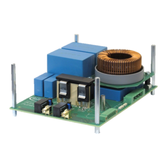
1200V HighSpeed 3 IGBT in TO-247PLUS
Evaluation Board
User Manual
About this document
Scope and purpose
This application note is a user guide for the 1200V HighSpeed 3 IGBT in TO-247PLUS evaluation board.
It explains the board's hardware and provides detailed instructions on how to use it for addressing
various measurement tasks. Finally, practical examples demonstrate the benefits of both, TO-247PLUS
and TO-247PLUS 4pin packages.
Intended audience
This document is intended for owners and users of the evaluation board.
Table of Contents
About this document .............................................................................................................................. 1
Table of Contents ................................................................................................................................... 1
1
Introduction .......................................................................................................................... 3
1.1
Purpose of the board .............................................................................................................. 3
1.2
Scope of delivery .................................................................................................................... 4
2
Hardware ............................................................................................................................... 5
2.1
Circuit and main components ................................................................................................. 5
2.2
Recommended accessories ................................................................................................... 6
3
Usage .................................................................................................................................... 8
3.1
Settings .................................................................................................................................. 8
3.1.1
Replacing switches or diodes ............................................................................................ 8
3.1.2
Changing between 3pin and 4pin packages ...................................................................... 9
3.1.3
Tuning gate voltages and resistors .................................................................................. 10
3.1.4
Adjusting and monitoring the heat sink temperature ........................................................ 11
3.2
Operation ............................................................................................................................. 11
3.2.1
Configurations ................................................................................................................. 11
3.2.2
Switching loss measurements ......................................................................................... 13
3.2.3
Efficiency or temperature measurements ......................................................................... 14
4
Examples ............................................................................................................................ 15
4.1
Turn-on loss reduction with a 4pin package ......................................................................... 15
4.2
Substituting parallel 40A devices with a 75A device ............................................................. 16
5
Appendix ............................................................................................................................. 18
5.1
Schematic drawing ............................................................................................................... 18
5.2
Board layout ......................................................................................................................... 19
5.3
Bill of materials ..................................................................................................................... 21
References ............................................................................................................................................ 24
Revision History ................................................................................................................................... 25
Application Note
www.infineon.com
Please read the Important Notice and Warnings at the end of this document
Revision 1.0
2017-11-15
Advertisement
Table of Contents

Related Manuals for Infineon EVAL-IGBT-1200V-TO247PLUS


Summary of Contents for Infineon EVAL-IGBT-1200V-TO247PLUS
-
Page 1: Table Of Contents
Appendix ..........................18 Schematic drawing ....................... 18 Board layout ......................... 19 Bill of materials ........................21 References ............................24 Revision History ........................... 25 Application Note Please read the Important Notice and Warnings at the end of this document Revision 1.0 www.infineon.com 2017-11-15... - Page 2 1200V HighSpeed 3 IGBT in TO-247PLUS Evaluation Board User Manual Introduction Dangerous Equipment! High Voltage Do NOT touch the board during operation. Depending on the configuration of the board and the chosen supply-voltage, life-threatening voltages might be present! Even brief accidental contact during operation might result in severe injury or death! Always make sure that the capacitors are discharged before touching the board.
-
Page 3: Introduction
User Manual Introduction Introduction The evaluation board EVAL-IGBT-1200V-TO247PLUS was developed as a test platform for 1200V IGBTs in TO-247PLUS and TO-247PLUS 4pin packages but can also be used for standard TO-247 and TO-247 4pin packages. This introductory section provides an overview of the potential applications of the evaluation board and lists the components included in the delivery. -
Page 4: Scope Of Delivery
The evaluation board is delivered together with spare parts and complete documentation in an environmentally friendly carton box as illustrated in Figure 2. As depicted, the carton box contains: Evaluation board EVAL-IGBT-1200V-TO247PLUS with a size of 172mm x 133mm x 72mm (LxWxH) 1200V HighSpeed 3 IGBTs IKQ50N120CH3, IKQ75N120CH3, IKY50N120CH3 and IKY75N120CH3 ... -
Page 5: Hardware
1200V HighSpeed 3 IGBT in TO-247PLUS Evaluation Board User Manual Hardware Hardware This section provides a short description of the board hardware. First, it explains the power circuitry, the main components and the connectors. Then, the application of the recommended accessories is discussed. -
Page 6: Recommended Accessories
1200V HighSpeed 3 IGBT in TO-247PLUS Evaluation Board User Manual Hardware An experimental analysis of a device’s switching behavior requires oscilloscope measurements of the gate voltage, the collector-emitter voltage as well as the collector current. While voltage measurements are straightforward, current measurements are more difficult to do, particularly in the presence of steep current slopes. - Page 7 1200V HighSpeed 3 IGBT in TO-247PLUS Evaluation Board User Manual Hardware Table 1 compares waveforms as well as switching losses measured with the metal foil SMD resistor and the coaxial shunt at various temperatures and voltages. As all measurements are done with exactly the same semiconductor devices, the differences can be attributed to the different current sensors.
-
Page 8: Usage
1200V HighSpeed 3 IGBT in TO-247PLUS Evaluation Board User Manual Usage Usage Due to its flexibility, the evaluation board can address a variety of measurement problems. While the previous sections explained the basic purpose as well as the hardware of the board, this section provides detailed instructions on how to set it up and operate it. -
Page 9: Changing Between 3Pin And 4Pin Packages
1200V HighSpeed 3 IGBT in TO-247PLUS Evaluation Board User Manual Usage Figure 6 Assembling a device onto the heat sink and the PCB Changing between 3pin and 4pin packages 3.1.2 Since the evaluation board has to serve as a universal test platform for TO-247-like packages with three as well as four leads, it contains special five pin sockets which can accommodate all package variants. -
Page 10: Tuning Gate Voltages And Resistors
1200V HighSpeed 3 IGBT in TO-247PLUS Evaluation Board User Manual Usage Tuning gate voltages and resistors 3.1.3 Figure 7.a illustrates the schematics of the driving circuitry implemented for both, the high side and the low side switch. It includes the relevant components of the circuitry and highlights the most important part labels which consist of a letter and a three-digit number. -
Page 11: Adjusting And Monitoring The Heat Sink Temperature
1200V HighSpeed 3 IGBT in TO-247PLUS Evaluation Board User Manual Usage Adjusting and monitoring the heat sink temperature 3.1.4 Switching losses are not only measured at room temperature but also at temperatures of 100°C and above. Consequently, a measurement setup must offer the possibility to adjust and monitor the case temperature of the devices under test. - Page 12 1200V HighSpeed 3 IGBT in TO-247PLUS Evaluation Board User Manual Usage and current. Measuring the current and voltage waveforms of the devices on the oscilloscope gives an impression of the switching behavior and allows a calculation of the switching losses. In order to maximize the accuracy and minimize the effort, it is recommended to make oscilloscope measurements on the low side device S : use configuration (1) to study the IGBT and configuration (2) to study the...
-
Page 13: Switching Loss Measurements
1200V HighSpeed 3 IGBT in TO-247PLUS Evaluation Board User Manual Usage Switching loss measurements 3.2.2 Switching losses can be determined using a double pulse test. It generates both a turn-off and a turn-on event by applying two consecutive pulses on the gate of the switch – hence the expression double pulse. Due to the fact that the circuit is not operated in a continuous fashion the self-heating of the semiconductors and the inductor is negligible. -
Page 14: Efficiency Or Temperature Measurements
1200V HighSpeed 3 IGBT in TO-247PLUS Evaluation Board User Manual Usage 8. If required, connect a power supply to the HEAT+/HEAT- terminals and set the voltage level according to 3.1.4. Monitor the temperature using an ohmmeter connected to SENSE+/SENSE-. 9. Connect a high voltage source to VIN and PGND and short VIN and VOUT. 10. -
Page 15: Examples
1200V HighSpeed 3 IGBT in TO-247PLUS Evaluation Board User Manual Examples Examples After the in-depth explanation of possible test settings and procedures that were provided in the previous section, this section shows two practical examples: a switching loss and a temperature measurement. Turn-on loss reduction with a 4pin package As extensively explained in [2] on the basis of 650V TRENCHSTOP™... -
Page 16: Substituting Parallel 40A Devices With A 75A Device
Examples Substituting parallel 40A devices with a 75A device With IKQ75N120CH3 and IKY75N120CH3 Infineon has pioneered assembling 1200V/75A IGBTs and full-rated diodes inside packages with a footprint of a standard TO-247. One interesting aspect of such high current ratings is the potential to limit the number of parallel devices. This section demonstrates that two parallel 40A IGBTs can be substituted by a single 75A IGBT. - Page 17 1200V HighSpeed 3 IGBT in TO-247PLUS Evaluation Board User Manual Examples The picture of the setup does not show the sources and loads. Besides the auxiliary supply which provides the driving voltages, a high voltage DC source and an active DC load were utilized to provide the required testing power of up to 4kW.
-
Page 18: Appendix
1200V HighSpeed 3 IGBT in TO-247PLUS Evaluation Board User Manual Appendix Appendix Schematic drawing Figure 12 Power and driving circuitry Figure 13 Auxiliary supply and LED indicators Application Note Revision 1.0 2017-11-15... -
Page 19: Board Layout
1200V HighSpeed 3 IGBT in TO-247PLUS Evaluation Board User Manual Appendix Board layout Figure 14 Layer 1 (top layer) Figure 15 Layer 2 Application Note Revision 1.0 2017-11-15... - Page 20 1200V HighSpeed 3 IGBT in TO-247PLUS Evaluation Board User Manual Appendix Figure 16 Layer 3 Figure 17 Layer 4 (bottom layer) Application Note Revision 1.0 2017-11-15...
-
Page 21: Bill Of Materials
Power Semiconductor Switch Infineon IKY75N120CH3 TO-247PLUS 4pin Q221 Power Semiconductor Switch Infineon IKY75N120CH3 TO-247PLUS 4pin U211 Isolated Single Channel Driver Infineon Technologies 1EDI60I12AH PG-DSO-8-59 U221 Isolated Single Channel Driver Infineon Technologies 1EDI60I12AH PG-DSO-8-59 Ceramic Capacitors C100 4u7 X7R 25V C 0805... - Page 22 1200V HighSpeed 3 IGBT in TO-247PLUS Evaluation Board User Manual Appendix R137 300k R 2512 R138 300k R 2512 R139 300k R 2512 R140 300k R 2512 R141 300k R 2512 R142 300k R 2512 R151 R 0805 R161 270R R 0805 R171 R 0805...
- Page 23 Spring Clip for TO-220 Fischerelektronik THFU 3 Others B200 NTC Resistor US Sensor TO103J2F E200 Power Resistor Vishay LTO100F4R700FTE3 G100 Voltage Regulator Infineon Technologies TLE4264-2G G111 Isolated DC/DC MuRata MGJ2D122005SC G112 Voltage Regulator Infineon Technologies IFX25401TEV G121 Isolated DC/DC MuRata MGJ2D122005SC G122...
-
Page 24: References
User Manual References References [1] Infineon Technologies AG: AN2017-01, TO247PLUS – Description of the packages and assembly guidelines, Revision 2.0, 2017-02-10 [2] Infineon Technologies AG: TRENCHSTOP™ 5 IGBT in a Kelvin Emitter Configuration – Performance Comparison and Design Guidelines, Revision 1.0, 2014-10-16 [3] Markus Billmann: Coaxial Shunts –... -
Page 25: Revision History
1200V HighSpeed 3 IGBT in TO-247PLUS Evaluation Board User Manual Revision History Revision History Major changes since the last revision Page or Reference Description of change Revision 1.0 – First Release – Klaus Sobe Application Note Revision 1.0 2017-11-15... - Page 26 AEC Q100 or AEC Q101 any function and other technical information documents Automotive Electronics © 2017 Infineon Technologies AG. given herein in the real application. Infineon Council. Technologies hereby disclaims any and all All Rights Reserved. warranties and liabilities of any kind (including WARNINGS...
Need help?
Do you have a question about the EVAL-IGBT-1200V-TO247PLUS and is the answer not in the manual?
Questions and answers