Table of Contents
Advertisement
Quick Links
EVAL_PMG1_B1_DRP kit guide
About this document
Scope and purpose
The EVAL_PMG1_B1_DRP is an evaluation kit for the EZ-PD™ PMG1-B1 USB Power Delivery (PD) microcontroller
(MCU) with an integrated buck-boost battery charger. EZ-PD™ PMG1-B1 is targeted for battery-powered
applications that are powered by USB-C PD such as cordless power tool chargers, wireless speakers, and
portable electronics. EZ-PD™ PMG1 (Power Delivery Microcontroller Gen1) is a portfolio of high-voltage USB-C
PD microcontrollers. These MCUs include Arm® Cortex® CPU core, USB-C PD controller, and configurable
integrated analog and digital peripherals. EZ-PD™ PMG1-B1 is targeted at embedded systems that power from
USB-C port and need an MCU to implement the product features.
Intended audience
This document is intended for designers who want to Sink or Source power through the USB-C PD port in
applications such as the cordless power tool charger, wireless speakers, and portable electronics. The kit can
be used to sink up to 100 W and source up to 27 W. The kit can also be used to charge 2 cell-5 cell batteries, and
the battery charging algorithm is implemented as part of PMG1-B1 SDK in ModusToolbox™ software.
User guide
Please read the sections "Important notice" and "Warnings" at the end of this document
002-37842 Rev. *B
www.infineon.com
2023-11-23
Advertisement
Table of Contents
Troubleshooting

Related Manuals for Infineon EVAL-PMG1-B1-DRP


Summary of Contents for Infineon EVAL-PMG1-B1-DRP
-
Page 1: About This Document
100 W and source up to 27 W. The kit can also be used to charge 2 cell-5 cell batteries, and the battery charging algorithm is implemented as part of PMG1-B1 SDK in ModusToolbox™ software. User guide Please read the sections “Important notice” and “Warnings” at the end of this document 002-37842 Rev. *B www.infineon.com 2023-11-23... -
Page 2: Important Notice
Boards provided by Infineon Technologies. The design of the Evaluation Boards and Reference Boards has been tested by Infineon Technologies only as described in this document. The design is not qualified in terms of safety requirements, manufacturing and operation over the entire operating temperature range or lifetime. -
Page 3: Safety Precautions
EVAL_PMG1_B1_DRP kit guide Safety precautions Safety precautions Note: The following warnings are regarding the hazards associated with development systems. Table 1 Safety precautions Warning: Remove or disconnect power from the drive before you disconnect or reconnect wires, or perform maintenance work. Wait five minutes after removing power to discharge the bus capacitors. -
Page 4: Table Of Contents
EVAL_PMG1_B1_DRP kit guide Table of contents Table of contents About this document ........................1 Important notice ..........................2 Safety precautions .......................... 3 Table of contents ..........................4 Introduction .......................... 6 Kit contents ............................. 6 Hardware not included with the kit ......................6 Getting started............................ - Page 5 EVAL_PMG1_B1_DRP kit guide Table of contents 3.3.5 Modifying 5-cell battery charging application to 3-cell battery charging application with cell monitoring and temperature monitoring ..................28 3.3.6 Modifying battery charging application to enable trickle charging or charging currents lower than 300 mA ............................28 Programming PMG1-B1 ......................
-
Page 6: Introduction
EVAL_PMG1_B1_DRP kit guide Introduction Introduction The EVAL_PMG1_B1_DRP is an evaluation kit for EZ-PD™ PMG1-B1 USB Power Delivery (PD) microcontroller (MCU) with integrated buck-boost battery charger. EZ-PD™ PMG1-B1 is targeted for battery powered applications that are powered by USB-C PD, such as cordless power tool chargers, wireless speakers, and portable electronics. -
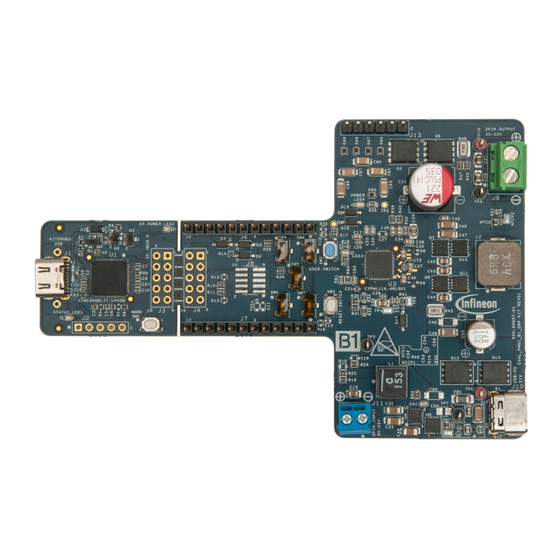
Page 7: Hardware
EVAL_PMG1_B1_DRP kit guide Hardware Hardware This chapter covers the hardware details of the EVAL_PMG1_B1_DRP kit board, a complete system overview, and description of the critical circuit blocks of the EVAL_PMG1_B1_DRP kit board schematic. For more details, see the schematics of the EVAL_PMG1_B1_DRP kit board on the kit web page. Board details Figure 1 shows the front view of the board with critical components highlighted. - Page 8 EVAL_PMG1_B1_DRP kit guide Hardware Figure 2 Board (back view) details Table 2 lists the major components of the EVAL_PMG1_B1_DRP kit. A detailed bill-of-materials list is available in the design files on the EZ-PD™ PMG1-B1 High-voltage MCU with USB-C & PD webpage.
- Page 9 EVAL_PMG1_B1_DRP kit guide Hardware REFDES Component Part number Description I/O header TSW-112-14-G-S CONN HEADER VERT 12POS 2.54MM I/O header TSW-112-14-G-S CONN HEADER VERT 12POS 2.54MM 2 pin OUTPUT load 691213510002 A 2-pin header to connect load up-to 5 A terminal for testing application Type-C connector 2012670005...
- Page 10 EVAL_PMG1_B1_DRP kit guide Hardware REFDES Description Default Pin 8: P1_7/BAT_TH_SNS Pin 9: UART2_RX/AIN1 Pin 10: UART2_TX/AIN2 Pin 11: DP_GPIO0 Pin 12: DM_GPIO1 I/O HEADER Populated Pin 1: B1_VDDD Pin 2: P1_3/AIN4 Pin 3: GND Pin 4: LOAD_SWITCH_EN_H Pin 5: P1_4/AIN3 Pin 6: I2C0_SCL Pin 7: I2C0_SDA Pin 8: SOURCE_OUTPUT_V_SELECT...
-
Page 11: Eval Pmg1-B1 Drp Kit Block Diagram And Functional Description
2-pin input DC 5V LDO Power conversion terminal 9 V – 22 V, 30 W INFINEON PART LOADED PARTS NO LOADED PARTS Figure 3 EVAL PMG1-B1 DRP kit block diagram PMG1 is a family of high-voltage power delivery microcontrollers. These microcontrollers include CPU core, Power Delivery controller, and configurable integrated analog and digital peripherals. -
Page 12: Buck-Boost Converter In Sink Mode
EVAL_PMG1_B1_DRP kit guide Hardware 2.2.1 Buck-boost converter in sink mode Power path BAT/LOAD BUS_IN Battery / Load BUS_CTRL BUS_C Figure 4 Buck-boost converter in sink mode of EVAL PMG1-B1 DRP kit This kit can negotiate USB power delivery contract up to 100 W (20 V @5A) as a sink with any USB-C Charger and use the negotiated Type-C VBUS to output any fixed voltage(5 V to 21 V) or charge a lithium-ion battery in sink mode as shown in Figure 4. -
Page 13: Battery Cell And Temperature Monitoring
EVAL_PMG1_B1_DRP kit guide Hardware 2.2.3 Battery cell and temperature monitoring Figure 6 Battery cell voltage and temperature monitoring circuit of EVAL PMG1-B1 DRP kit When the kit is used to charge a battery of 2 cell to 5 cell, individual cell voltages and battery temperature can be monitored using the circuitry shown in Figure 6. -
Page 14: I/O Header For Measuring Different Gpios
EVAL_PMG1_B1_DRP kit guide Hardware 2.2.4 I/O header for measuring different GPIOs Figure 7 GPIO header of EVAL PMG1-B1 DRP kit GPIOs of PMG1-B1 are brought through J6 and J7 to be accessible. 2.2.5 5-V LDO and power LED Figure 8 5-V LDO and power LED This is an external 5-V LDO with an allowed maximum load current of 400 mA. -
Page 15: Status Led Or User Led
EVAL_PMG1_B1_DRP kit guide Hardware 2.2.6 STATUS LED or USER LED Figure 9 STATUS LED or USER LED The STATUS LED helps to indicate the state of the kit. Different states of the kit are listed in Table Table 5 STATUS LED configuration Sl. -
Page 16: Kitprog3 (Psoc™ 5Lp Mcu)
EVAL_PMG1_B1_DRP kit guide Hardware KitProg3 (PSoC™ 5LP MCU) An onboard PSoC™ 5LP MCU (CY8C5868LTI-LP039)-based KitProg3 module is used to program and debug the EZ-PD™ PMG1-B1 microcontroller. Figure 11 PSoC™ 5LP MCU device The PSoC™ 5LP MCU device interfaces with a PC through a Type-C USB connector (J1), and functions as a bridge between the PC and EZ-PD™... -
Page 17: Mode Button
EVAL_PMG1_B1_DRP kit guide Hardware Do the following to establish the UART connection on older revisions of the PMG1 kit boards as listed above: Connect J6.10 (EZ-PD™ PMG1-B1 MCU UART Tx) to J3.8 (KitProg3 UART Rx). Connect J6.9 (EZ-PD™ PMG1-B1 MCU UART Rx) to J3.10 (KitProg3 UART Tx). 2.3.1 Mode button The KitProg3 mode button on the EVAL_PMG1_B1_DRP kit enables the KitProg3 module to enter the... -
Page 18: Kit Operation Or Demo
EVAL_PMG1_B1_DRP kit guide Kit operation or demo Kit operation or demo This section describes how to configure the EVAL_PMG1_B1_DRP kit to demonstrate its functionality as a USB Type-C Power Sink/source mode. External hardware required for demo A USB Type-C power adapter (for example, Apple power adapter, Google Type-C charger, HP laptop AC •... -
Page 19: Running Demo#1
EVAL_PMG1_B1_DRP kit guide Kit operation or demo 3.2.1.2 Running Demo#1 LED4 LED3 Figure 13 Connection for DEMO#1 (sink mode) Program the EVAL_PMG1_B1_DRP kit with USB PD DRP firmware or SINK only firmware by connecting a • type-c cable on J1. Use default switch settings as shown in Table •... -
Page 20: Common Problems And Troubleshooting
EVAL_PMG1_B1_DRP kit guide Kit operation or demo 3.2.1.3 Common problems and troubleshooting If the demo is not functional, follow these guidelines to troubleshoot: Ensure that the correct firmware is programmed on the EVAL_PMG1_B1_DRP kit board • Ensure that the power adapter is working as intended. •... -
Page 21: Running Demo#2
EVAL_PMG1_B1_DRP kit guide Kit operation or demo 3.2.2.2 Running Demo#2 Figure 15 Connection for DEMO#2 (Source mode) Program PMG1-B1 with USB PD DRP firmware by connecting Type-C on J1. For more details, see • Programming PMG1-B1. Ensure that you use the default switch settings as shown in Table •... -
Page 22: Common Problems And Troubleshooting
EVAL_PMG1_B1_DRP kit guide Kit operation or demo 3.2.2.3 Common problems and troubleshooting If the demo is not functional, follow these guidelines to troubleshoot: Ensure that the correct firmware is programmed on the EVAL_PMG1_B1_DRP kit board • Ensure that the correct sink device is connected. •... -
Page 23: Common Problems And Troubleshooting
EVAL_PMG1_B1_DRP kit guide Kit operation or demo Connect the positive and negative terminals of 5-cell battery to J9; follow polarity as shown on the • EVAL_PMG1_B1_DRP kit board. Connect the USB-C power adapter to J10 of the kit using USB-C to C cable •... -
Page 24: Running Demo#4
EVAL_PMG1_B1_DRP kit guide Kit operation or demo 3.2.4.2 Running Demo#4 For firmware modifications, see Enabling cell monitoring and temperature monitoring in battery.. • For hardware modifications, use the switch settings as shown in Table • Table 10 Switch configuration in battery charging Switch Position Description... - Page 25 EVAL_PMG1_B1_DRP kit guide Kit operation or demo Figure 17 EZ-PD™ Configurator Modify “Min/Max Operating current(mA)” in “Sink PDO 1” to any value less than 5000 as shown in Figure 18. • Figure 18 Modifying maximum input current in sink mode of DRP and SINK FW After modifying as instructed above, save, build, and program PMG1-B1.
-
Page 26: Modifying Output Voltage In Sink Mode Of Drp Or Sinkfirmware
EVAL_PMG1_B1_DRP kit guide Kit operation or demo Note: Buck-boost turns-ON only when the available input power is greater than 7.5 W. 3.3.2 Modifying output voltage in sink mode of DRP or sinkfirmware Modify the output voltage in Sink mode of DRP or sink firmware through the device configurator. Open Device Configurator in ModusToolbox™. -
Page 27: Migrating From 5-Cell Battery To 3-Cell Battery Charging Application Without Cell Monitoring And Temperature Monitoring
EVAL_PMG1_B1_DRP kit guide Kit operation or demo Figure 20 Output voltage is changing through Device Configurator Build the application in ModusToolbox™ and program PMG1-B1. • 3.3.3 Migrating from 5-cell battery to 3-cell battery charging application without cell monitoring and temperature monitoring Do the following firmware modification: Update the TOTAL_BATTERY_CELL_COUNT macro value from 5 to 3 in config.h file, as shown in Figure 21. -
Page 28: Enabling Cell Monitoring And Temperature Monitoring In Battery
EVAL_PMG1_B1_DRP kit guide Kit operation or demo 3.3.4 Enabling cell monitoring and temperature monitoring in battery Table 11 for firmware modifications to enable cell monitoring and temperature monitoring of battery. • Table 11 Firmware modification to enable cell monitoring and temperature monitoring Macro name Default Modify... - Page 29 EVAL_PMG1_B1_DRP kit guide Kit operation or demo Figure 22 Modifying current sense resistor value using Device Configurator After the modification, save, build, and program PMG1-B1. • Note: Maximum allowed charging current is 3.5 A with 10 mΩ of current sense resistor(R48). User guide 002-37842 Rev.
-
Page 30: Programming Pmg1-B1
EVAL_PMG1_B1_DRP kit guide Programming PMG1-B1 Programming PMG1-B1 PSOC™ 5 (U1-CY8C5868LTI-LP039) is preprogrammed in the EVAL_PMG1_B1_DRP kit board. The EVAL_PMG1_B1_DRP kit firmware is available in the ModusToolbox™ software. Follow the steps in this section to program the PMG1-B1 device. This firmware update is necessary for successful kit operation. This section describes ModusToolbox™... -
Page 31: Programming Pmg1-B1 Device
EVAL_PMG1_B1_DRP kit guide Programming PMG1-B1 Programming PMG1-B1 device Download and install ModusToolbox™ Programmer and follow these steps to program PMG1-B1: Connect the device to the host computer, by connecting a Type-C cable on J1. Select the device name in the •... -
Page 32: Connect The Device
EVAL_PMG1_B1_DRP kit guide Programming PMG1-B1 4.2.2 Connect the device 1. If the device is not powered, the status message “Not Powered” is displayed in the Status Bar. Click Power to power-up the device. 2. Click Connect. ModusToolbox™ Programmer communicates with the device and displays various messages in the Log. -
Page 33: Program The Device
EVAL_PMG1_B1_DRP kit guide Programming PMG1-B1 4.2.3 Program the device Click Program. ModusToolbox™ Programmer downloads the program file on to the device and displays messages in the Log. Figure 24 Programming through ModusToolbox™ Programmer User guide 002-37842 Rev. *B 2023-11-23... -
Page 34: Related Documents
EVAL_PMG1_B1_DRP kit guide Related documents Related documents Overview: USB-C Power Delivery Controllers [2] Product webpage: − USB-C High Voltage Microcontrollers [3] Kit webpage: − EVAL_PMG1_B1_DRP kit [4] Datasheets − EZ-PD™ PMG1-B1 USB Type-C Buck-boost controller, Single-port AN232553 - Getting started with EZ-PD™ PMG1 MCU on ModusToolbox™ software KitProg3 user guide ModusToolbox™... -
Page 35: Glossary
EVAL_PMG1_B1_DRP kit guide Glossary Glossary Field-effect transistor GPIO General-purpose input/ output Integrated circuit Light-emitting diode Microcontroller MOSFET Metal oxide semiconductor field effect transistor Not applicable Overvoltage protection Power adapter Power delivery Power data object PFET P-channel field effect transistor PSoC™ Programmable system-on-chip System-on-chip User guide... - Page 36 EVAL_PMG1_B1_DRP kit guide Glossary Upstream facing port Universal Serial Bus USB-PD Universal Serial Bus Power Delivery Undervoltage protection User guide 002-37842 Rev. *B 2023-11-23...
-
Page 37: Revision History
EVAL_PMG1_B1_DRP kit guide Revision history Revision history Document Date Description of changes revision 2023-07-27 New kit guide. 2023-09-26 Updated minor content wordings. Updated the Programming PMG1-B1 section. 2023-11-23 Released to web. User guide 002-37842 Rev. *B 2023-11-23... -
Page 38: Disclaimer
For information on the types in question please contact your nearest Published by Infineon Technologies office. Except as otherwise explicitly approved by Infineon Infineon Technologies AG Technologies in a written document signed by 81726 Munich, Germany authorized...
Need help?
Do you have a question about the EVAL-PMG1-B1-DRP and is the answer not in the manual?
Questions and answers