Table of Contents
Advertisement
Quick Links
Advertisement
Table of Contents

Subscribe to Our Youtube Channel
Related Manuals for Knauer Azura P 4.2S


Summary of Contents for Knauer Azura P 4.2S
- Page 1 Pump P 4.2S Instructions HPLC HPLC Document No. V6873...
- Page 2 KNAUER. Support: Do you have questions about the installation or the operation of your instrument or software? International Support: Contact your local KNAUER partner for support: www.knauer.net/en/Support/Distributors-worldwide Support in Germany (Austria & Switzerland on case-to-case basis): Phone:...
-
Page 3: Table Of Contents
Table of contents 1. Product information ............1 1.1 Device overview . - Page 4 5.7.6 Firmware Wizard: ..........16 5.7.6.1 Firmware Wizard: Assign static IP address .
- Page 5 10. Technical data ............. . 39 10.1 General .
-
Page 6: Product Information
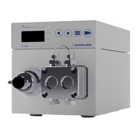
1. Product information 1.1 Device overview The HPLC pump P 4.2S with pump heads can be used as feed pumps or dosing pumps in analytical or preparative applications. Pumps transport solvents or dissolved samples through the HPLC system. Intended use Note: Only use the device for applications that fall within the range of the intended use. -
Page 7: Rear View
Product information 1.3.2 Rear view Legend Serial number UKCA mark Power connection - bushing On/off switch Interface RS-232 LAN connection Pin header for remote control Hole for the ground connection CE mark Fig. 2: Pump, rear view Features Analytical pump head with a flow rate range from 0.01 – 10 ml/min and ƒ... -
Page 8: Scope Of Delivery
Legend Flow rate Material Fig. 3: Pump head with inlays 2. Scope of delivery Note: Only use spare parts and accessories made by KNAUER or a company authorized by KNAUER. Instructions (German/English) ƒ Power supply cable ƒ AZURA accessories kit ƒ... -
Page 9: Basic Safety Instructions
Only use a given PEEK fitting for one specific port and never re-use it ƒ for other ports. Always install new PEEK fittings on each separate port. Follow KNAUER or manufacturer's instructions on caring for the col- ƒ umns Other important topics for your security are listed alphabetically in the following list: Flammability: Organic eluents are highly flammable. -
Page 10: Where Is Use Of The Device Prohibited
Opening the device Only have the device opened by a KNAUER Technical Customer Service representative or a KNAUER authorized company. Warnings Possible dangers that can arise from a device are classified into personal injury or damage to property. -
Page 11: Decontamination
Devices that reach KNAUER without a service request form (decontami- Decontamination report nation report) will not be repaired. If you return a device to KNAUER, you must enclose the completed service request form: www.knauer.net/Dokumente/service/VFM-SBS-EN.pdf. AZURA® Pump P 4.2S Instructions V6873... -
Page 12: Symbols And Signs
4. Symbols and signs The following table explains symbols and labels which are used on the device or in the instruction: Symbol Meaning The device complies with the product-specific requirements of the European Union. The device complies with the product-specific requirements of the United Kingdom. -
Page 13: Unpacking And Setup
Electronic defect Electronic hazard when using an identically constructed power adapter from another manufacturer. Only use spare parts and accessories from KNAUER or a company authorized by KNAUER. For power supply, use the supplied power cable to meet the specifi- cations which are described in the chapter Technical Data. -
Page 14: Conditions
Unpacking and setup 5.2.1 Conditions The electrical power supply at the installation site has to be connected ƒ directly to the nearest main power line. The power has to be free from ripple, residual current, voltage peaks ƒ and electromagnetic interference. The connectors for the mains voltage are grounded accordingly. -
Page 15: Integrating The Pump Into The Hplc System
Unpacking and setup Legend Foam padding Fig. 4: Transport protection between the ends of the pumps capillaries and the housing (this is an example) Integrating the pump into the HPLC system The pump can be integrated into an HPLC system by connecting the pressure sensor or the pump head outlet and the HPLC system with capil- laries. -
Page 16: Connecting The Eluent Line To The Pump Head
Unpacking and setup Piston backflushing To flush the backpiston space, aspirate flushing solution with the syringe included in the accessory kit. Ensure regular backpiston flushing for opti- mal seal lifetime. Solvent flow path The pump head takes the liquid in from the solvent bottle and conveys it to the pressure sensor or directly into the HPLC system (version without pressure sensor). -
Page 17: Ports On The Rear Side
Unpacking and setup Ports on the rear side Legend Serial number UKCA mark Power connection - bushing On/off switch Interface RS-232 LAN connection Pin header for remote control Hole for the ground connection CE mark Fig. 8: Pump, rear view External devices External devices like a computer can be connected to the pump in three different ways:... -
Page 18: Connecting Cables To The Pin Header
Unpacking and setup Contact Explanation ERROR IN/OUT TTL-compatible input Min. 10 mA ƒ Low-active ƒ This contact can either send an error signal or can receive one. The pump can thus be stopped by the error signal (ERROR-IN) or ensure that a second device is stopped by an error signal that is output at the ERROR-OUT. -
Page 19: Connecting The Device To A Computer
Finish the installation. Afterwards take the device into operation. Connecting the device to a computer Note: HPLC devices from KNAUER only work with IP addresses, which have been assigned by IPv4. IPv6 is not supported. This chapter describes how to set up a chromatography system in a local area network (LAN) and how a network administrator can integrate this LAN into your company network. -
Page 20: Configuring The Router
5.7.3 Configuring the router The router is preset at the factory. For IP address, user name, and pass- word information, refer to the router instruction: www.knauer.net/en/Support/Library/PC-hardware. Procedure 1. To open the router configuration, start your Internet browser and enter the IP address (not for all routers). -
Page 21: Controlling Several Systems Separately In The Lan
Unpacking and setup 5.7.5 Controlling several systems separately in the LAN Devices connected to a LAN communicate through ports, which are part of the IP address. If several chromatography systems are connected to the same LAN and are to be controlled separately, you can use different ports to avoid interference. -
Page 22: Firmware Wizard: Assign Dynamic Ip Address
APIPA is a service that allows devices to obtain a dynamic IP address even without a DHCP server in the network. The AZURA® Neo platform from KNAUER supports APIPA. The device has to be set to DHCP for this. If no DHCP server responds, the APIPA implementation ensures that the device gives itself a random IP address from the IP address range reserved for APIPA (169.254.x.x). -
Page 23: Initial Startup
6. Initial startup Note: It is mandatory to perform a running-in procedure after a pump head maintenance, or if new pump heads are installed on a pump. If a pump was not in operation for a long time, e.g. after shipment, a running-in procedure might be necessary to obtain the best pump per- formance. -
Page 24: Led Status
Initial startup LED status The status of the device is indicated by an LED on the front side. The color of the LED shows the current status. Status Green Pump is ready (idle status). Green flashing Pump is running. Yellow Firmware upload in progress. -
Page 25: Display Symbols
Initial startup 6.3.1 Display symbols Symbol Explanation RFID tag is found. 10.00 If the RFID symbol is blinking, the 10.00 RFID tag is not found. If no RFID symbol is displayed, RFID is switched off. 10.00 RFID hardware has failed. 10.00 Dosing mode is active. -
Page 26: Controlling Via Keypad
Initial startup 6.3.2 Controlling via keypad The keypad consists of 4 buttons, which allow monitoring the device or changing the settings. Button Function Change flow on the main screen ƒ Prev/next screen in menu branch ƒ Increment/decrement value in edit ƒ... -
Page 27: Menu Structure
Initial startup 6.3.5 Menu Structure EXT.MENU IS ON! FIRMWARE KNAUER UPDATE P4.2S DISPLAY Init UPDATE 1.0 min CONTROL PUMP 3.00 10.00 SETUP ► SETUP ► DHCP AN.INPUT Input HEAD Head: SETUP ► inactive SETUP ► Manual Auto STANDBY 21:15:31 Head: AN.OUT... -
Page 28: Setting The Flow Rate
Initial startup 6.3.5.1 Setting the flow rate In case of the pump without pressure sensor the actual required flow rate is dependent on the resulting counter pressure. The absolute deviation is dependent on the compressibility and the viscosity of the used solvent and on the pump. -
Page 29: Setting The Shutdown Threshold
Initial startup Procedure Figure 3. Confirm the edit mode by Pmin pressing the enter button. Pmax 100 4. Enter the desired maximum Fig. 22: Minimum pressure value and the desired mini- mum value by using the arrow buttons. 5. Press the start/stop button to end the edit mode. -
Page 30: Piston Seal Wash
Initial startup Procedure Figure 3. Confirm the edit mode by pres- Imin sing the enter button. Imax 100 Fig. 25: Minimum power 4. Enter the desired maximum value consumption and the desired minimum value by using the arrow buttons. 5. Press the start/stop button to end the edit mode. -
Page 31: Choosing Pump Head
Initial startup 6.3.6 Choosing pump head Procedure Figure 1. Choose the menu Head HEAD setup by pressing the menu SETUP ► button. Fig. 27: Choosing pump head 2. Enter the submenu Head Head: auto by pressing the menu Auto button again. Fig. -
Page 32: Software
Initial startup Procedure Figure 1. Prime liquid with the syringe. 2. Hold down start/stop button for 3 sec. in order to start the flushing. Fig. 30: Start/Stop button 6.3.8 Software To be able to control the pump using chromatography software, the com- puter has to be connected to the device either with a RS-232 cable or a LAN cable. -
Page 33: Activating The Analog Control
Initial startup Control Range and Description command specification PMIN10(?) RD/WR 0-400 Minimum pressure for 10 ml pump head (in 0.1 MPa) PMIN50(?) RD/WR 0-150 Minimum pressure for 50 ml pump head (in 0.1 MPa) PMAX10(?) RD/WR 0-400 Maximum pressure for 10 ml pump head (in 0.1 MPa) PMAX50(?) RD/WR 0-150 Maximum pressure for 50 ml pump head (in 0.1 MPa) IMIN10(?) -
Page 34: Controlling The Flow Rate Analog
Initial startup Note: It is only possible to use the communication connection which has been chosen before the adjustment (RS-232 or LAN). If you reset the pump to RS-232 or LAN, the device is set to standard settings. The pump does not start with switched on flow. The flow stops at active short circuit connection GROUND and START IN. -
Page 35: Starting With A Short-Circuit
Initial startup Note: The parameter can be changed via a terminal connection. Deac- tivating and activating the analog control, the parameter has to be set again. Alternative: Installation of a permanent short circuit connection. Legend Pressure in 0.1 MPa 10.00 Flow rate in ml/min Fig. -
Page 36: Starting Directly After Connection To Power Supply
Initial startup Note: During the interruption, the horizontal arrow (A) remains in the display, because the pump is still in operation status. Procedure 1. Connect the pump with an applicable terminal program. 2. Connect the pump using a LAN or RS-232. 3. -
Page 37: Functionality Tests
7.1 Installation Qualification (IQ) The customer may request the Installation Qualification, which is free of charge. In case of a request, the technical support of KNAUER or a pro- vider authorized by KNAUER performs this functionality test during the installation. -
Page 38: Troubleshooting
4. Check device for leaks. 5. Pay attention to system messages. Further measures Inform the Technical Support of KNAUER. 8.1 LAN Go through the following steps, in case no connection between the com- puter and the devices can be established. Check after each step if the problem is solved. -
Page 39: Possible Problems And Solutions
Pump without pressure sensor: Pay attention to ƒ the influence of the pressure on the flow rate (will not be compensated). Inform the technical support of the ƒ manufacturer. Further measures Inform the Technical Support of KNAUER. AZURA® Pump P 4.2S Instructions V6873... -
Page 40: Maintenance And Care
Technical Support. 9.1 Maintenance contract The following maintenance work on the device may only be performed by KNAUER or a company authorized by KNAUER and is covered by a sepa- rate maintenance contract: Opening the device. -
Page 41: Removing The Pump Head
Maintenance and care 9.3.1.2 Removing the pump head Prerequisites The pump head has been flushed with suitable solvent. Chemical burns Skin damage from aggressive or toxic eluents. Wear protective gloves. Flush the pump head before changing. Component defect Possible damage to the pump piston by tilting the pump head. Tighten diagonally opposite fastening screws evenly one turn at a time. -
Page 42: Check Valves
Maintenance and care Procedure Figure 1. Hold the pump head and tighten the four fixing screws one after the other. 2. Mount the piston seal wash tubings 3. Tighten the inlet fitting and the outlet fitting Fig. 44: Installing the pump head Check valves 9.3.2 Clogged check valves do not open and close properly. -
Page 43: Installing The Check Valves
Maintenance and care 9.3.5 Installing the check valves Insert the check valves in the direction of the flow. The notch of the check valve points downward. Insert the NP check valves in the direction of the flow. The arrow on the NP check valve points upward. Prerequisites The check valves have dried. -
Page 44: Technical Data
10. Technical data Note: The pump was adjusted under specific conditions. If the pump is operated under different conditions (flow, pressure, eluent), a calibration of the pump may be necessary at the selected place of operation. 10.1 General Pump type Dual-piston pump with main and auxiliary piston Flow rate range... -
Page 45: Technical Parameters
Technical data 10.3 Technical parameters Supply frequency See type plate of the power supply Power consumption Maximum 40 W at the 24 V connection of the pump Protection type IP 20 Temperature range 4-40 °C / 39.2–104 °F Air humidity Below 90 % non-condensing Power supply 110-230V AC Dimensions... -
Page 46: Chemical Compatibility Of Wetted Materials
The following list contains information about the chemical compatibility of all wetted materials which are used in devices made by KNAUER. The data bases on a literature research on the manufacturer specifications of the materials. The wetted materials of this device are listed in the chapter „Technical data“. -
Page 47: Polyimide (Vespel®)
Chemical compatibility of wetted materials 11.2.3 Polyimide (Vespel®) This material is wear-resistant and permanent resilient thermically (up to 200 °C) as well as mechanically. It is chemically broadly inert (pH range 1-10) and is especially resistant against acidic to neutral and organic solvents, but vulnerable to pH strong chemical or oxidizing environments: It is incompatible with concentrated mineral acids (such as sulfuric acid), glacial acetic acid, DMSO and THF. -
Page 48: Fluorinated Rubber (Fkm)
Chemical compatibility of wetted materials 11.2.11 Fluorinated rubber (FKM) The elastomer consisting of fluorinated hydrocarbon stands out due to a high resistance against mineral oils, synthetic hydraulic fluids, fuels, aromatics, and many organic solvents and chemicals. However, it is not compatible with strong alkaline solvents (pH value >13) like ammonia, and acidic solvents (pH value <1), pyrrole and THF. -
Page 49: Glass, Glass Fibre, Quartz, Quartz Glass
Chemical compatibility of wetted materials 11.3.8 Glass, glass fibre, quartz, quartz glass These mineral materials are resistant against corrosion and wear and are mostly chemical inert. They are compatible with oils, fats and solvents and show a high resistance against acids anf lyes up to pH values of 3-9. Con- centrated acids (especially hydrofluoric acid) may embrittle and corrode the minerals. -
Page 50: Repeat Orders
12. Repeat orders For repeat orders of spare parts use the enclosed packing list. Contact the Technical Support in case there are any questions on spare parts or accessories. 12.1 Accessories Order number Name AZURA accessories kit FZA01 ® AZURA® Pump P 4.2S accessories kit FPGA Maintenance kit for 10 ml pump head A96423... -
Page 51: Available Pump Heads
Repeat orders 12.2 Available pump heads Name Order number 10 ml stainless steel pump head with stainless steel AHB40 inlay 10 ml pump head with ceramic inlay AHB32 10 ml pump head with ceramic inlay and titanium AHB32DA fittings 10 ml pump head with Hastelloy-C inlay AHB43 10 ml pump head stainless steel for normal phase AHB40BA... -
Page 52: Legal Information
ƒ and damage caused by clogged capillaries Packaging and transport damage ƒ In the event of device malfunctions, directly contact the manufacturer. KNAUER Wissenschaftliche Geräte GmbH Hegauer Weg 38 14163 Berlin, Germany Telephone: +49 30 809727-111 Telefax: +49 30 8015010 E-mail: support@knauer.net... -
Page 53: Disposal
2001), old devices manufactured by KNAUER are marked as waste electrical and electronic equipment: 160214. 14.2 WEEE-Registration number KNAUER as a company is registered by the WEEE number DE 34642789 in the German "Elektroaltgeräteregister" (EAR). The number belongs to category 8 and 9, which, among others, comprise laboratory equipment. - Page 54 Customer approval Prior to installation at the customer site, the customer has reviewed the OQ document and agrees with the design and scope. Company name: Name Function Reviewed & approved Date Signature VIQ-Installation-Qualification-Device, Version 3.1 Date: Signature: Revision:...
- Page 55 KNAUER Wissenschaftliche Geräte GmbH. Scope The customer can request the Installation Qualification. In case of a request, the technical support of KNAUER or a provider authorized by KNAUER performs this functionality test during the installation. The IQ is a standardized document and includes the following: ƒ...
- Page 56 Installation Qualification Tests Test Description Specification Passed Failed Comment /LOR No. Identify the device. The name on the device matches the name on the delivery order. Check the device for No transport damage is transport damage. observed. Check the scope of The scope of delivery delivery.
- Page 57 List of rectifications (LOR) Type of Description of Persons LOR No. Test No. Action plan Due date Date/signature deviation* the deviation responsible * Type of deviation: A = acceptable (e.g. not a GMP-critical deviation) N = not acceptable Continuation of qualification activities into the next qualification phase is only possible when deviation is rectified. T = temporarily acceptable a) Release and use of the system is possible, even when the deviation is not rectified.
- Page 58 List of changes to the document Revision no. Description of change Additional information Date/signature VIQ-Installation-Qualification-Device, Version 3.1 Date: Signature: Revision:...
- Page 59 Installation Qualification (IQ) for a Device 10. Certificate and approval A KNAUER employee or an employee authorized by KNAUER has checked the device and performed all tests described in the IQ. The IQ form has to be signed by an authorized person. The scope of the IQ meets the customer‘s requirements.
- Page 60 Appendix: List of supporting documents Test no. Description VIQ-Installation-Qualification-Device, Version 3.1 Date: Signature: Revision:...
- Page 61 Latest KNAUER instructions online: www.knauer.net/library KNAUER Phone: +49 30 809727-0 Wissenschaftliche Geräte GmbH Fax: +49 30 8015010 Hegauer Weg 38 E-mail: info@knauer.net 14163 Berlin Internet: www.knauer.net © KNAUER 2023...
Need help?
Do you have a question about the Azura P 4.2S and is the answer not in the manual?
Questions and answers