Table of Contents
Advertisement
Quick Links
Advertisement
Table of Contents

Related Manuals for Knauer AZURA P 2.1S


Summary of Contents for Knauer AZURA P 2.1S
- Page 1 Pump P 2.1S/P 4.1S Instructions HPLC Document No. V6870...
- Page 2 KNAUER Wissenschaftliche Geräte GmbH. KNAUER Wissenschaftliche Geräte GmbH 2018 All rights reserved. AZURA® is a registered trademark of KNAUER Wissenschaftliche Geräte GmbH. Note for BlueShadow products: The content of this instruction is transferable to the BlueShadow product.
-
Page 3: Table Of Contents
Table of contents 1. Product information ..............1 1.1 Device overview . - Page 4 5.6.6 Firmware Wizard: ........... 14 5.6.6.1 Firmware Wizard: Assign static IP address .
- Page 5 11.1 General ..............35 11.2 Plastics.
-
Page 6: Product Information
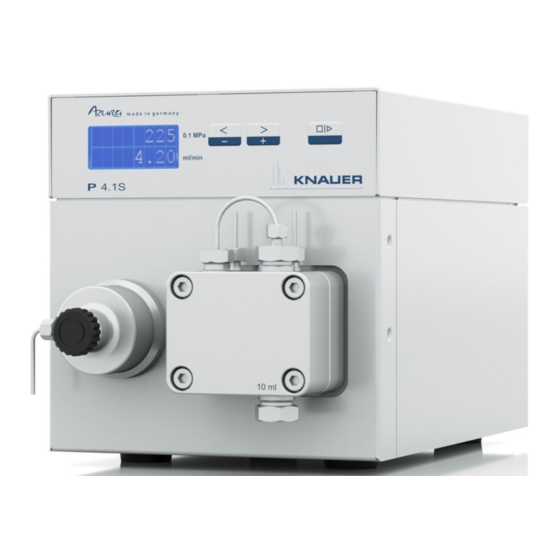
Product information 1. Product information 1.1 Device overview The HPLC pumps P 4.1S/ P 2.1S with pump heads can be used as feed pumps or dosing pumps in analytical or preparative applications. Pumps transport solvents or dissolved samples through the HPLC system. Intended use Note: Only use the device for applications that fall within the range of... -
Page 7: Rear View
Product information 1.3.2 Rear view Legend CE mark Serial number Interface RS-232 LAN connection Pin header for remote control Power connection - bushing Hole for the ground connection Fig. 3 Pump, rear view Features ƒ Analytical pump head with a flow rate range from 0.001 – 9.999 ml/min and a pressure of up to 400 bar ƒ... -
Page 8: Pump Heads
Fig. 4 Pump head with inlays 2. Scope of delivery Note: Only use spare parts and accessories made by KNAUER or a company authorized by KNAUER. ƒ 24V power adapter with power cable ƒ Instructions (German/English) ƒ AZURA accessories kit ƒ... -
Page 9: Safety Equipment
ƒ Only use a given PEEK fitting for one specific port and never re-use it for other ports. Always install new PEEK fittings on each separate port. ƒ Follow KNAUER or manufacturer's instructions on caring for the col- umns Other important topics for your security are listed alphabetically in the following list: ƒ... -
Page 10: Where Is Use Of The Device Prohibited
Opening the device Only have the device opened by a KNAUER Technical Customer Service representative or a KNAUER authorized company. Warnings Possible dangers that can arise from a device are classified into personal injury or damage to property. -
Page 11: Symbols And Signs
Symbols and signs Devices that reach KNAUER without a service request form (decontami- Decontamination report nation report) will not be repaired. If you return a device to KNAUER, you must enclose the completed service request form: www.knauer.net/Dokumente/service/VFM-SBS-EN.pdf. 4. Symbols and signs... -
Page 12: Power Supply
Electronic defect Electronic hazard when using an identically constructed power adapter from another manufacturer. Only use spare parts and accessories from KNAUER or a company authorized by KNAUER. For power supply, use the supplied power cable and power adapter to meet the specifications which are described in the chapter Technical Data. -
Page 13: Removing Transport Protection
Symbols and signs Process 1. Set-up the package in such a way that you can read the label. 2. Using the utility knife, cut the adhesive tape and open the pack- aging. 3. Lift the foam padding. Take out the accessories kit and the manu- 4. -
Page 14: Ports On The Rear Side
Symbols and signs Procedure Process Figure 1. Stick the tube through the 2. Stick the tube through the seal ring . The narrow end must point away from the nut. 3. Stick the cutting ring onto the tube. Fig. 6 Tube with nut, seal ring and cutting ring 4. -
Page 15: Pin Header Connectors
Symbols and signs 5.5.1 Pin header connectors Contact Explanation GROUND Reference point of the voltage at the signal inputs. START IN TTL-compatible input ƒ Min. 10 mA ƒ Low-active At stand alone, RS-232 or LAN control stops the motor at a short circuit contact between START IN and GROUND. -
Page 16: Ground
Electronic defect Electronic hazard when using an identically constructed power adapter from another manufacturer. Only use spare parts and accessories from KNAUER or a company authorized by KNAUER. The ground connection for the pump has a designated hole with a thread M3 on the back of the device. -
Page 17: Configuring The Lan Settings
Symbols and signs 4. Install the chromatography software. 5. Switch on the device and run the chromatography software. 5.6.1 Configuring the LAN settings The LAN uses only one server (which is normally the router) from that the devices automatically receive their IP address. Prerequisites ƒ... -
Page 18: Configuring The Router
Symbols and signs 2. Use the power supply to connect the router to the mains power sys- tem. 5.6.3 Configuring the router The router is preset at the factory. For IP address, user name, and pass- word information, refer to the router instruction: http://bit.ly/KNAUER_PC-Hardware_EN. -
Page 19: Firmware Wizard
Symbols and signs 5.6.6 Firmware Wizard: Changing LAN settings by entering the serial number requires that the device has been found by Firmware Wizard after browsing. Changing LAN settings by MAC address does not require that the device has been found after browsing. The IP address can be part of another network. -
Page 20: Initial Startup
Initial startup 5. Restart the device. Result The device can now be reached via the static IP address. 6. Initial startup Note: It is mandatory to perform a running-in procedure after a pump head maintenance, or if new pump heads are installed on a pump. If a pump was not in operation for a long time, e.g. -
Page 21: Operation
Initial startup been successfully completed, the status of the pump with its current flow rate is displayed. The pump is ready for operation. Operation The pump can be operated in three ways: ƒ Using the keyboard at the device ƒ Via chromatography software with integrated drivers for the pump ƒ... -
Page 22: Menu Structure
Initial startup 6.2.2 Menu Structure Start-up routine Status display Pressure switch off Current switch off Control RS-323: ANALOG HEAD: HEAD: Pump head 50ml 10ml Fig. 12 Menu Structure 6.2.2.1 Setting the Flow Rate In case of the pump without pressure sensor the actual required flow rate is dependent on the resulting counter pressure. -
Page 23: Adjusting Pressure Turn-Off (Only P 4.1S)
Initial startup Procedure Figure 1. Use the arrow keys to set a value for the flow rate. Fig. 13 Display control 2. Check if the right value ap- pears on the display. Result ƒ The setting is completed and the pump runs at the set flow rate. 6.2.2.2 Adjusting pressure turn-off (only P 4.1S) ƒ... -
Page 24: Flushing The Pistons
Initial startup ƒ Set the maximum power switch off for the pump to limit the pump pressure. ƒ Set the minimum power switch off so as to avoid a dry run of the pump at highly reduced maximum power consumption (e. g. if leaking). The pump is preset to a standard value for the maximum power switch off. -
Page 25: Choosing Pump Head
Initial startup Procedure Figure 1. Connect the outlet to the waste container with a hose 2. Connect the inlet to the syringe with a hose 3. Fill up flushing solution with the syringe through the pump head until there are Fig. -
Page 26: Software
Initial startup Procedure Figure 1. Prime liquid with the sy- ringe. 2. Hold down start/stop key until flushing starts. 6.2.5 Software To be able to control the pump using chromatography software, the com- puter must be connected to the device either with a RS232 cable or a LAN cable. - Page 27 Initial startup ƒ 1 stop bit ƒ no parity check Control com- Range and specifi- Description mand cation ADJ10(?) RD/WR 100-2000 Adjust parameter for 10 ml pump head ADJ50(?) RD/WR 100-2000 Adjust parameter for 50 ml pump head CORR10(?) RD/WR 0-300 Correction parameter for 10 ml pump head CORR50(?) RD/WR 0-300...
-
Page 28: Activating The Analog Control (Prior To Firmware Version 1.37)
Initial startup Control com- Range and specifi- Description mand cation REMOTE Command to prevent a manual parameter input, with exception of stopping the flow via START/STOP button. ERRORS? Display of the last 5 error codes. Starts the flow Stops the flow 6.2.5.4 Activating the analog control (prior to firmware version 1.37) The analog control is switched on and off via a serial port RS-232 with an applicable hyperterminal program. -
Page 29: Controlling The Flow Rate Analog
Initial startup Procedure Figure 1. To scroll through, press both A-IN buttons simultaneously. 2. Using the right arrow buttons, ANALOG scroll until it shows ANALOG. Fig. 23 Display control Result The display shows a star symbol left to the flow rate. You cannot adjust the flow rate any longer via the key pad. -
Page 30: Starting Directly After Connection To Power Supply
Installation Qualification The customer may request the Installation Qualification, which is free of (IQ) charge. In case of a request, the Technical Support of KNAUER or from a provider authorized by KNAUER performs this functionality test during the installation. The Operation Qualification is a standardized KNAUER document and includes the following: ƒ... -
Page 31: Troubleshooting
Operation Qualification at following intervals: The test intervals are determined by the use of the device. Execution The OQ can be carried out either by the Technical Support of KNAUER or from a provider authorized by KNAUER. 8. Troubleshooting First measures 1. -
Page 32: Possible Problems And Solutions
Troubleshooting 5. Turn off all devices, router, and computer. First switch on the router and wait until it has successfully completed its self-test. Then turn on the devices and the computer. ƒ Has this been successful? 6. Replace the patch cable to the device with that no connection could be established. - Page 33 ƒ Pump without pressure sensor: Pay atten- tion to the influence of the pressure on the flow rate (will not be compensated). ƒ Inform the technical support of the manu- facturer. Further measures Inform the Technical Support of KNAUER. AZURA® Pump P 2.1S/P 4.1S Instructions V6870...
-
Page 34: Maintenance And Care
Technical Support. 9.1 Maintenance contract The following maintenance work on the device may only be performed by KNAUER or a company authorized by KNAUER and is covered by a sepa- rate maintenance contract: ƒ Opening the device. -
Page 35: Removing The Pump Head
Maintenance and care Pump head Type (ml) Screw fitting Screw fitting, Capillary connec- tion (Nm) Fitting, outlet inlet (Nm) (Nm) AHC20 AHC20BA AHC20CA 9.3.1.2 Removing the pump head Prerequisites The pump head has been flushed with suitable solvent. Chemical burns Skin damage from aggressive or toxic eluents. -
Page 36: Check Valves
Maintenance and care Procedure Figure 1. Tighten 4 fixing screws alternately and hold the pump head. 2. Mount the piston seal wash tubings 3. Tighten the inlet fitting and the outlet fitting Check valves 9.3.2 Clogged check valves do not open and close properly. They cause pres- sure fluctuations and irregular flow. -
Page 37: Technical Data
Maintenance and care Prerequisites ƒ The check valves have dried. Component defect Damage to components due to excessive tightening possible. Observe the torque of the screw connection Use 5 Nm torque for stainless steel fi ttings. Use 1 Nm torque for PEEK fi ttings. Procedure Figure 1. -
Page 38: Communication
Maintenance and care System protection ƒ Pump with pressure sensor: and P adjustable and I adjustable ƒ Pump with pressure sensor: I and I adjustable Wetted materials For ceramic: Graphite fiber reinforced PTFE, FKM, PEEK, sapphire, aluminum oxide (Al ), titanium (only P 4.1S) For stainless steel: Stainless steel, graphite fiber reinforced... -
Page 39: Dimensions
Maintenance and care 10.4 Dimensions Fig. 27 Dimensions of the pump in mm AZURA® Pump P 2.1S/P 4.1S Instructions V6870... -
Page 40: Chemical Compatibility Of Wetted Materials
The following list contains information about the chemical compatibility of all wetted materials which are used in devices made by KNAUER. The data bases on a literature research on the manufacturer specifications of the materials. The wetted materials of this device are listed in the chapter „Technical data“. -
Page 41: Polyimide (Vespel®)
Chemical compatibility of wetted materials 11.2.3 Polyimide (Vespel®): This material is wear-resistant and permanent resilient thermically (up to 200 °C) as well as mechanically. It is chemically broadly inert (pH range 1-10) and is especially resistant against acidic to neutral and organic solvents, but vulnerable to pH strong chemical or oxidizing environments: It is incompatible with concentrated mineral acids (such as sulfuric acid), glacial acetic acid, DMSO and THF. -
Page 42: Fluorinated Rubber (Fkm)
Chemical compatibility of wetted materials 11.2.11 Fluorinated rubber (FKM): The elastomer consisting of fluorinated hydrocarbon stands out due to a high resistance against mineral oils, synthetic hydraulic fluids, fuels, aromatics, and many organic solvents and chemicals. However, it is not compatible with strong alkaline solvents (pH value >13) like ammonia, and acidic solvents (pH value <1), pyrrole and THF. -
Page 43: Glass, Glass Fibre, Quartz, Quartz Glass
Chemical compatibility of wetted materials 11.3.8 Glass, glass fibre, quartz, quartz glass: These mineral materials are resistant against corrosion and wear and are mostly chemical inert. They are compatible with oils, fats and solvents and show a high resistance against acids anf lyes up to pH values of 3-9. Con- centrated acids (especially hydrofluoric acid) may embrittle and corrode the minerals. -
Page 44: Device Variants
Chemical compatibility of wetted materials Name Order Number Rebuild-kit for 50 ml pump head KEL-F valve A5821-2 cover, FFKM O-ring Rebuild-kit for 10 ml pump head for water A5823 application sapphire piston, GFPseals, FKM O-rings Inlet-bushing kit for 1/8‘‘ capillary for 10 ml A58202 pump head Inlet-bushing kit for 1/16‘‘... -
Page 45: Available Pump Heads
Legal information Name Order Number AZURA Pump P 2.1S with 10 ml ceramic APG90EB ® pump head AZURA Pump P 2.1S with 10 ml Hastelloy-C APG90EC ® pump head AZURA Pump P 2.1S with 50 ml stainless APG90FA ® steel pump head AZURA Pump P 2.1S with 50 ml ceramic APG90FB... -
Page 46: Declaration Of Conformity
160214. 160214. 12.3.2 WEEE-Registration number KNAUER as a company is registered by the WEEE number DE 34642789 in the German "Elektroaltgeräteregister" (EAR). The number belongs to category 8 and 9, which, among others, comprise laboratory equipment. -
Page 47: Abbreviations And Terminology
Abbreviations and terminology 13. Abbreviations and terminology Here you can find information on the abbreviations and terminology used in this instruction. Term Explanations Good Laboratory Practice – quality assurance for laboratories Gradient Time-dependent composition of solvent (mobile phase) on low-pressure or high-pressure side of system Operating mode of HPLC system;... -
Page 48: Index
Index 14. Index Pump head 7 Accessories 3 AVV-marking 41 Removing the pump head 30 Router Configuring the router 13 Chemical compatibility 35 Safety 3, 4 Decontamination 5 Setting the Flow Rate 17 Disposal 41 Setup 11 Characteristics 12 Connection issues 13 Features 2 Port 12 Flammability... - Page 49 Latest KNAUER instructions online: https://www.knauer.net/en/Support/User-manuals KNAUER Phone: +49 30 809727-0 Wissenschaftliche Geräte GmbH Fax: +49 30 8015010 Hegauer Weg 38 E-Mail: info@knauer.net 14163 Berlin Internet: www.knauer.net © KNAUER 2018...
Need help?
Do you have a question about the AZURA P 2.1S and is the answer not in the manual?
Questions and answers