Knauer BlueShadow 80P Instructions Manual
Hide thumbs
Also See for BlueShadow 80P:
- Instructions manual (74 pages) ,
- Service instructions manual (62 pages)
Table of Contents
Advertisement
Quick Links
BlueShadow
Pump 80P
Instructions
HPLC
Distributed By:
Greyhound Chromatography and Allied Chemicals
6, Kelvin Park, Birkenhead, Merseyside, CH41 1LT, UK
Tel:
+44 (0) 151 649 4000
Email: info@greyhoundchrom.com Sales: sales@greyhoundchrom.com
Web:
www.greyhoundchrom.com
Fax: +44 (0) 151 649 4001
Document no. V7680
Advertisement
Table of Contents

Subscribe to Our Youtube Channel
Related Manuals for Knauer BlueShadow 80P


Summary of Contents for Knauer BlueShadow 80P
- Page 1 BlueShadow Pump 80P Instructions HPLC Document no. V7680 Distributed By: Greyhound Chromatography and Allied Chemicals 6, Kelvin Park, Birkenhead, Merseyside, CH41 1LT, UK Tel: +44 (0) 151 649 4000 Fax: +44 (0) 151 649 4001 Email: info@greyhoundchrom.com Sales: sales@greyhoundchrom.com Web: www.greyhoundchrom.com...
- Page 2 Keep the instructions for future reference. Note: In case you require a version of this instruction in another language, please submit your request including the corresponding document num- ber via e-mail or fax to KNAUER. Customer Telefon: +49 30 809727-111 (9-17h, Central European Time)
-
Page 3: Table Of Contents
Table of contents Product information ..............1 Intended use . - Page 4 Table of contents 5.6.5 Controlling several systems separately in the LAN ......22 5.6.6 Analog control ............22 Operation .
- Page 5 Table of contents Check valves ..............52 9.5.1 Removing the check valves .
-
Page 6: Product Information
1. Product information Note: Only use the device for applications that fall within the range of the intended use. Otherwise, the protective and safety equipment of the device could fail. Automatic piston backflushing increases the service life of the seals and pistons, and removes salt and other substances from the area behind the seals. -
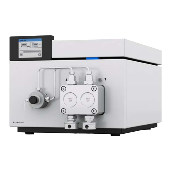
Page 7: Device Overview
Product information Device overview Legend Touchscreen Pressure sensor Venting screw Tube connections for the piston backflushing Pump head Fig. 1: Front view Legend Serial number Socket for the LPG valve block Events terminal strip Opening of the fan Power switch Remote terminal strip Interface RS-232 LAN connection... -
Page 8: Pump Heads
Product information Pump heads Pump head for use in preparative applications: Standard model, stainless steel ƒ Stainless steel or titanium inlays for biocompatible applications: ƒ 100 ml, 250 ml, 500 ml, 1000 ml For biocompatibility, pump heads with titanium inlays can be used. The pump heads can be exchanged by the user. -
Page 9: Basic Safety Instructions
ƒ Only use a given PEEK fitting for one specific port and never re-use it for other ports. Always install new PEEK fittings on each separate port. ƒ Follow KNAUER or manufacturer’s instructions on caring for the co- lums. BlueShadow Pump 80 P Instructions (V 7680) -
Page 10: Warning Notifications
Take the device completely out of operation by disconnecting the power plug from the power supply (wall socket or power strip). Opening the device The device may be opened by the KNAUER Technical Support or any company authorized by KNAUER only. Warning notifications Possible dangers related to the device are divided into personal and material damage in these instructions. -
Page 11: Decontamination
Decontamination Report Devices without a completed Decontamination Report will not be repai- red. If you would like to return a device to KNAUER, make sure to enclose a completed Decontamination Report with the device: https://www.knauer.net/decontamination-report. -
Page 12: Symbols And Signs
(NRTL). The certified device or system has successfully passed the quality and security tests. 4. Scope of delivery Note: Only use original parts and accessories made by KNAUER or a company authorized by KNAUER. Power cable ƒ BlueShadow Pump 80P with pump head ƒ... -
Page 13: Installation
Installation 5. Installation This chapter describes all preparatory steps prior to start-up. Preparations 5.1.1 Operating location The intended use be ensured only if the requirements for ambient con- ditions of the operating environment are met. You will find the ambient conditions under Technical Data. -
Page 14: Power Supply
Electronic defect Electronic hazard when using an identically constructed power adapter from another manufacturer. Only use spare parts and accessories from KNAUER or a company authorized by KNAUER. Conditions The electrical power supply at the installation site must be connected directly to the nearest main power line. -
Page 15: Connecting The Piston Backflushing
Installation Process 1. Set-up the package in such a way that you can read the label. 2. Using the utility knife, cut the adhesive tape and open the packaging. 3. Lift the foam padding. Take out the accessories kit and the manual. 4. -
Page 16: Eluent Inlet
Installation Eluent inlet Note: The acessory Kit includes PTFE tubing and PETP bushing/sealing ring, which can be used for standard HPLC applications. For applications with aggressive solvents, PEEK or stainless steel parts are available. The eluent lines are connected by the eluent inlet to the pump head. Legend Knurled-head screw Eluent inlet... -
Page 17: Connecting The Eluent Inlet To The Pump Head
Installation 5.3.1 Connecting the eluent inlet to the pump head Process Figure 1. With the knurled-head screw , screw the elu- ent inlet into the inlet screw fitting of the pump head. 2. Turn the eluent inlet until the intake manifold input points forward. -
Page 18: Changing The Setup To Lpg
Installation Process Figure Pump head 1. Push the Teflon hose through the fastening 100 ml ƒ screw and the cutting 250 ml ƒ ring 500 ml ƒ 2. Insert the hose end as far as possible into the eluent inlet fitting the pump head. 3. -
Page 19: Connecting The Lpg Module
Installation Legend Ternary LPG valve block Fastening screws with sealing ring plug Fig. 10: Ternary LPG valve block 5.4.2 Connecting the LPG module Always place seals in pairs on both fastening screws. The plug should not be detached during operation. Process Figure 1. -
Page 20: Controlling The Lpg Module
Installation 5.4.3 Controlling the LPG module Manual control of the pump via touchscreen ƒ PC control with chromatography software ƒ Control There are 3 ways to operate the pump: Via the pin head ƒ As part of a LAN, via the LAN connector of the router ƒ... -
Page 21: Pin Header Connectors
Installation 5.5.1 Pin header connectors Connection Function 1TTL TTL-compatible output Levels: passive 0 V ƒ active 5 V ƒ Pulse: 5 V for at least 1000 ms ƒ 2TTL TTL-compatible output Levels: passive 0 V ƒ active 5 V ƒ Pulse: 5 V for at least 1000 ms ƒ... - Page 22 Installation Connection Function Reference point of the voltage at the signal inputs. Relay Contact The contact is on a floating basis. Its setting depends on the settings in the Control Unit or software. Steady-rate signal: passive = open relay contact ƒ...
-
Page 23: Events Terminal Strip
Installation Connection Function Error IN TTL Input Low-active ƒ Secure switching threshold at least 10 mA After receiving a signal (short-circuit to ground) from an external device, an error message appears and the device stops. Error GND Reference point of the voltage at the signal inputs. +24V Event-controlled switching of 24 V against GND... -
Page 24: Connecting Cables To The Pin Header
Installation Legend Status display Events Events terminal strip Fig. 14: Events Remote Connector 5.5.3 Connecting cables to the pin header To control one device through another, you use the pin header. To use remote control, you have to connect cables to the pin header. The single ports are used to exchange control signals. -
Page 25: Connecting The Device To A Computer
Finish the installation. Bring the device into operation. Connecting the device to a computer Note: HPLC devices from KNAUER only work with IP addresses, which have been assigned by IPv4. IPv6 is not supported. This chapter describes how to set up a chromatography system in a local area network (LAN) and how a network administrator can integrate this LAN into your company network. -
Page 26: Connect Devices To Lan
Configuring the router The router is preset at the factory. Information about address, user name and password is noted in the router manual: www.knauer.net/router Procedure 1. To open the router configuration, start your Internet browser and enter the IP address (not for all routers). -
Page 27: Integrating The Lan Into The Company Network
Installation Result Once the router has assigned IP addresses to all devices, the chromato- graphy software can be used to remotely control the system. 5.6.4 Integrating the LAN into the company network A network administrator can integrate the LAN into your company net- work. -
Page 28: Operation
6. Operation Switching on the pump Note: Operator errors and clogged capillaries can cause high pressure spikes. Component defect Possible damage to the pump head due to dry running. Make sure that solvent fl ows through the pump head and piston backfl ushing. -
Page 29: Operating Mode Lpg
Operation Process Figure 5. Choose Purge A, Purge B, Purge 35.000 ml/min Purge C, Purge D or Purge to start the purging process. 0 bar 6. Tap to stop the purging process. Purge A Purge Stop 6.2.1 Operating mode LPG 1. In the gradient directory of the Setup menu, select the gradient mode LPG ternary or otherwise LPG binary (Diagram A and B). -
Page 30: Operating Mode Isocratic Or Hpg
Operation 6.2.2 Operating mode isocratic or HPG 1. In the Gradient directory of the Setup menu, choose Type: Select HPG A, HPG B, HPG C, HPG D or none. 2. Activate desired channels A-D (Channel A-D: ON-OFF). Setup: Gradient Channel A: Channel C: Channel B: Channel D:... -
Page 31: Overview Of The Keys
Operation Using the touchscreen All fields with a gray background are touch-sensitive and can be edited. The buttons for setting or modifying functions are always labeled, e.g., START. The pump starts to work when you tap the button and the label on the button changes to STOP. -
Page 32: Menu Structure
Operation Button Function Explanation Year Confirm the year – Create a new program – line with time indicator Load Load program – Edit Edit the program – Del/Delete Delete the program – Table Program line display Menu structure The pump has the following touchscreen menu structure (see Fig. 19): Creating programs (Program menu) ƒ... - Page 33 Operation Fig. 19: Menu structure pump GUI BlueShadow Pump 80 P Instructions (V 7680)
-
Page 34: Setup Menu
Operation 6.3.2 Setup menu In the Setup menu, fundamental parameters for controlling the pump are specified. Process Figure 1. Tap the Setup menu to dis- Menu > Setup play options Network Analog out 2. Tap options to display the current pump parameters. Pump head Analog in Gradient... - Page 35 Operation Value Analog in Time constant IN Select the time constant for analog input, to be used for signal smoothing (0.1-10.0 S). The larger the value of the selected time constant, the stronger the applied signal smoothing. Setup: Analog In 0.000 Actual interpreted flow: ml/min Set to Zero...
- Page 36 Operation Value Event check Check the Events terminal strip. Start IN: ƒ Error-IN: ƒ Statuses at the digital inputs Active only: ƒ Connections Event 1 to Event 8 and 24 V Gradient Type and channel for high-pressure gradient (HPG), low-pressure gradient (LPG) and isocratic system can be set: Channel A-D: ON/OFFActivate of up to four ƒ...
-
Page 37: Solvent Menu
Operation 6.3.3 Solvent menu In the Solvent menu you enter data for the compressibility of the solvents Process Figure 1. Tap Solvent to display cur- rent settings. 2. Tap on value in field with gray background to adjust the value to compressibility. 3. -
Page 38: Glp Menu
Operation 6.3.4 GLP menu In the GLP menu, statistical data on important parameters of the pump are displayed. Process Figure 1. Tap the GLP menu to display Menu > GLP operating parameters. 2. Tap the gray highlighted Instrument values to display all available Components options. - Page 39 Operation Creating a program The use of the device is demonstrated using the example of a program to be created: Program 01 is to be used to create a solvent gradient (channels A and B) with constant flow rate of 10 ml/min. The percentage of solvent A is to be continuously decreased from 100 % to 0 % within 5.0 minutes.
- Page 40 Operation Process Figure should be tapped to go Edit: to the superordinate level, or Program 1 Line: hold for two seconds to go to RFID 10.0 ml/min the operational display. 0 %A 100 %B 0 %C LPG: Event Displaying the program lines Process Figure 1.
- Page 41 Operation Deleting program lines Program lines can be deleted while creating a program. Process Figure 1. Tap Tab in the program's Program 1 Line 2 editing window to display the ml/min bar %A %B %C %D Events program lines. 10.00 10.00 2.
- Page 42 Operation Changing a program Process 1. Tap the Program menu in order to display the program list. 2. Tap the desired program number and Edit to edit the program. 3. Change the desired values. 4. Save setting. should be tapped to go to the superordinate level, or hold for two seconds to go to the operational display.
-
Page 43: Link Menu
Operation Process Figure 3. Enter the date for the pro- Date: gram start. 28.04.2010 (DD:MM:YYYY) > should be tapped to save the settings. Month Year 5. Enter the time for the pro- Time: gram start. 11:43:00 (hh:mm:ss) > should be tapped to save the settings. - Page 44 Operation Creating a Link Note: The setting Wait for external signal makes the pump wait for an external start signal before the link is run. The setting Wait: no wait runs the link without interruption. Process Figure 1. Tap the Link menu to display Edit: the Link list.
-
Page 45: Setting Minimal And Maximal Pump Pressure
Operation Process Figure 6. Tap STOP to stop the pump. Link 1 (P1 / R1) 0.70 min 7. Tap Restart to repeat the Link. RFID 10.00 8. Tap Finishto exit the loaded ml/min Link. LPG: 79 %A 21 %B 0 %C Event STOP Fig. -
Page 46: Configuring Control Signals
Operation Configuring control signals For test purposes or in some other cases, it can make sense to manually enter these signals. Symbol Explanation Pulse Process 1. In the status display, tap on the field with a gray background next to Event to view the current settings in the Select: Events. 2. -
Page 47: Functional Tests
Installation Qualification (IQ) The customer may request the Installation Qualification, which is free of charge. In case of a request, the Technical Support of KNAUER or from a provider authorized by KNAUER performs this functionality test during the installation. -
Page 48: Troubleshooting
8. Troubleshooting First measures for troubleshooting: Check all screw fittings. ƒ Check whether air has gotten into the supply lines. ƒ Check device for leaks. ƒ Further measures: Check errors against error list ƒ Contact the technical support hotline of the manufacturer ƒ... -
Page 49: Possible Problems And Solutions
Troubleshooting 7. Make sure that the IP port of the device matches the port in the chro- matography software. Possible problems and solutions Problem Solution Pump will not turn on The power cable must be connected to the power supply. Inspect the power cable to ensure that ƒ... -
Page 50: System Messages
Troubleshooting System messages Explanation of the touchscreen's system messages. They are sorted alphabetically. System message Solution Auto pump head: Switch the device off and on. ƒ Head data uninitialized! Check whether a pump head with RFID ƒ recognition has been installed. Repeat the automatic configuration ƒ... - Page 51 Troubleshooting System message Solution Cannot read data from Switch the device off and on. Inform the FRAM technical support in case the system mes- sage repeats itself. Cannot read RTC Switch the device off and on. Inform the technical support in case the system mes- sage repeats itself.
- Page 52 Troubleshooting System message Solution Memory error Switch the device off and on. Inform the technical support in case the system mes- sage repeats itself. Minimum pressure! Increase the pressure or adjust the low- ƒ System stopped er pressure limit. Restart the system. ƒ...
- Page 53 Troubleshooting System message Solution this program is used in First quit or delete wakeup program WAKEUP (WakeUp) and then edit or delete the data by means of the chromatography software. Time already exists Correct the time entry. Time table line is empty Edit the program line.
-
Page 54: Maintenance And Care
9. Maintenance and care Organic eluents are toxic above a certain concentration. Ensure that work areas are always well-ventilated! When performing maintenance tasks on the device, always wear safety glasses with side protection, protective gloves, and an overall. All wetted components of a device, e. g. flow cells of detectors or pump heads and pressure sensors for pumps, have to be flushed with isopropa- nol first and water afterwards before being maintained, disassembled or disposed. -
Page 55: Fittings
Maintenance and care Fittings Tools Torque wrench 9.3.1 Torque values Pump head, stainless steel Torque 100 ml 19 Nm 250 ml 15 Nm 500 ml 12 Nm 1000 ml 12 Nm 9.3.2 Tighten fittings Process Figure 1. Always tighten the inlet screw and the outlet screw 1 with a torque wrench. 2. -
Page 56: Installing The Pump Head
Maintenance and care Note: Loosen the opposite pairs of fastening screws of the pump head evenly and alternately to prevent the pump pistons on the inside from jamming. Process Figure 1. To remove the capillary, loos- en the capillary screw fittings at the pump head outlet and pressure sensor inlet. -
Page 57: Check Valves
Maintenance and care Check valves Clogged check valves do not open and close properly. They cause pressure fluctuations and irregular flow. If it is impossible to clean the check valves, replace the whole unit. Pay attention to the torques while tightening. -
Page 58: Cleaning The Check Valve
Maintenance and care 9.5.2 Cleaning the check valve The check valves are not disassembled for cleaning but they are cleaned as a unit. Process 1. Put the valve in a beaker with solvent e. g. isopropanol. 2. Put the beaker in an ultrasonic bath for at least 10 minutes. 3. -
Page 59: Technical Data
Technical data 10. Technical data 10.1 Solvent delivery Pump type Dual-piston pump with main and auxiliary piston Flow rate range 100 ml pump head: ƒ 0.1-99.9 ml/min 250 ml pump head: ƒ 0.1-249.9 ml/min 500 ml pump head: ƒ 0.1-499.9 ml/min 1000 ml pump head: ƒ 0.1-999.9 ml/min Maximum pressure 100 ml pump head: ƒ... -
Page 60: Communication
Technical data 10.2 Communication Control ƒ RS-232 ƒ Remote control connections (Stop, Flow, ƒ Pressure, Error) RFID for automatic pump head detection ƒ Touchscreen ƒ Programming 10 programs, 9 program links (Links), WAKE UP program Supply frequency 50/-60 Hz Power Pump: maximum 320 W ƒ... -
Page 61: Repeat Orders
Repeat orders 11. Repeat orders 11.1 Devices Article Order Number Pump with 100 ml pump head, stainless steel, APD20KA accessories Pump with 100 ml pump head, stainless steel APD20KB with titanium inlays, accessories Pump with 250 ml pump head, stainless steel, APD20LA accessories Pump with 250 ml pump head, stainless steel APD20LC with titanium inlays, accessories... -
Page 62: Chemical Compatibility Of Wetted Materials
The following list contains information about the chemical compatibility of all wetted materials which are used in devices made by KNAUER. The data bases on a literature research on the manufacturer specifications of the materials. The wetted materials of this device are listed in the chapter “Technical data”. - Page 63 Chemical compatibility of wetted materials Polyimide (Vespel®) This material is wear-resistant and permanent resilient thermically (up to 200 °C) as well as mechanically. It is chemically broadly inert (pH range 1-10) and is especially resistant against acidic to neutral and organic solvents, but vulnerable to pH strong chemical or oxidizing environments: It is incompatible with concentrated mineral acids (such as sulfuric acid), glacial acetic acid, DMSO and THF.
-
Page 64: Metals
Chemical compatibility of wetted materials Polychlortrifluorethylene (PCTFE, Kel-F®) The semi-crystalline thermoplastic material is plasticizer-free and dimen- sionally stable, even in a wide temperature range (−240 °C to+205 °C). It is moderately resistent against ether, halogenated solvents and toluene. Halogenated solvents over +60 °C and chlorine gas should not be used. Fluorinated rubber (FKM) The elastomer consisting of fluorinated hydrocarbon stands out due to a high resistance against mineral oils, synthetic hydraulic fluids, fuels,... -
Page 65: Non-Metals
Chemical compatibility of wetted materials 12.4 Non-metals Diamond-like carbon (DLC) This material is characterized by a high hardness, a low coefficient of fric- tion and thus low wear. In addition, it is highly biocompatible. DLC is inert against all acids, alkalis and solvents commonly used in HPLC. Ceramic Ceramic is resistant against corrosion and wear and is fully biocompati- ble. -
Page 66: Legal Information
A warranty seal is attached on some devices. The warranty seal is col- orcoded. A blue seal is used by the assembly or technical support of KNAUER for devices to be sold. After repair, service technicians stick an orange seal in identical position. If unauthorized persons interfere with the device or the seal is damaged, the warranty claim becomes void. -
Page 67: Declaration Of Conformity
160214. 160214. 13.5.2 WEEE registration KNAUER as a company is registered by the WEEE number DE 34642789 in the German “Elektroaltgeräteregister” (EAR). The number belongs to category 8 and 9, which, among others, comprises laboratory equipment. -
Page 68: Abbreviations And Terminology
14. Abbreviations and terminology Here you can find information on the abbreviations and terminology used in this manual. Term Explanations Good Laboratory Practice - quality assurance for laboratories. Gradient Time-dependent composition of solvent (mobile phase) on low-pressure or high-pressure side of system High Pressure Gradient. - Page 69 Abbreviations and terminology BlueShadow Pump 80 P Instructions (V 7680)
- Page 70 Latest KNAUER instructions online: www.knauer.net/library...
Need help?
Do you have a question about the BlueShadow 80P and is the answer not in the manual?
Questions and answers