Table of Contents
Advertisement
Quick Links
Advertisement
Table of Contents

Subscribe to Our Youtube Channel
Related Manuals for Knauer Azura Pump P 6.1L


Summary of Contents for Knauer Azura Pump P 6.1L
- Page 1 Pump P 6.1L Instructions HPLC Document no. V6890...
- Page 2 Support: Do you have questions about the installation or the operation of your instrument or software? International Support: Contact your local KNAUER partner for support: www.knauer.net/en/Support/Distributors-worldwide Support in Germany (Austria & Switzerland on case-to-case basis): Phone: +49 30 809727-111 (workdays 9-17h CET)
-
Page 3: Table Of Contents
Table of Contents General ................1 About these instructions . - Page 4 Table of contents 3.5.2 Rear view ............10 Meaning of the LEDs .
- Page 5 Table of contents 4.11.5 Firmware Wizard: Setting a dynamic IP address ......30 4.11.6 Setting a static IP address via APIPA ........31 4.12 Remote control .
- Page 6 Table of contents Removing a leakage ............56 Transport and storage .
- Page 7 Table of contents Ceramic ............67 Alumina (Al2O3) .
-
Page 8: General
These operating instructions are an integral part of the device. It must be kept in the immediate vicinity of the device and accessible to the user at all times. You can download these and other instructions from the KNAUER web- site: www.knauer.net/library. Signal words Possible dangers related to the device are distinguished in personal and material damages. -
Page 9: Legal Information
1.4.4 Warranty seal A blue or orange warranty seal is affixed to some devices. A blue seal is used by KNAUER’s Manufacturing or Customer Support ƒ for devices to be sold. After repair, service technicians attach an orange seal onto the identi- ƒ... -
Page 10: Basic Safety Instructions
Operation in potentially explosive areas without special and additio- ƒ nal explosion protection. Contact the KNAUER Customer Support for more information. User qualification The user is qualified to handle the device if all of the following points apply: He has at least a basic knowledge of liquid chromatography. -
Page 11: Operator Responsibility
Basic safety instructions Operator responsibility The operator is any person who operates the device himself or leaves it to a third party for use and who bears the legal product responsibility for the protection of the user or third parties during operation. The obligations of the operator are listed below: Know and follow the applicable work safety regulations ƒ... -
Page 12: Working With Solvents
Basic safety instructions Working with solvents 2.6.1 General requirements The user is trained for handling different solvents. ƒ Note recommended solvents and concentrations in these instructions ƒ in order to avoid personal injury or damage to the device. For exam- ple, certain chemicals may cause PEEK capillaries to swell or burst (see „12 Chemical compatibility of wetted materials“, p. -
Page 13: Specific Environments
Devices which are shipped without the completed document “Service request form and decontamination report” will not be repaired. If you would like to return a device to KNAUER, make sure to enclose the com- pleted document: www.knauer.net/servicerequest. AZURA® Pump P 6.1L Instructions V6890... -
Page 14: Product Information
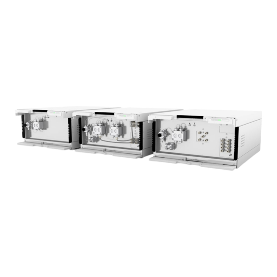
Product information 3. Product information Features AZURA® L features The AZURA® Pump P 6.1L1 is a member of the AZURA® L product line and shares a number of common features. Removable front cover, for optional pump and/or user protection. ƒ Instrument stability through a large base area and low center gravity. -
Page 15: Device Variants
Product information Parameter Stainless steel Bio-Inert Size 50 µl, 100 µl, 200 µl 250 µl Pressure 1000 bar 400 bar Piston backflushing The piston backflushing function automatically flushes the rear piston area of the pump head upon switch-on and in continuous mode. Upon switch-on: The rear piston area of the pump head is automatical- ƒ... -
Page 16: Views
Product information Views 3.5.1 Front view Isocratic pump The isocratic pump is equipped with a pressure sensor with an integra- ted inline filter and a venting screw. Depending on version, a 2-channel degasser with a solvent selection valve is also integrated. Legend Pressure sensor Pump head... -
Page 17: Rear View
Legend Serial number Service board drive B (HPG version only, used exclusively for direct control of drive B via KNAUER Service Tool) Pin header LAN connector Power connection and power switch Fig. 4: Rear view (example) -
Page 18: Meaning Of The Leds
Product information Meaning of the LEDs There are three LEDs and a standby switch on the front of the de- vice. The figure shows the LED panel when the device is switched off. Fig. 5: LEDs on front of the device The LEDs show different colors depending on the operating status. -
Page 19: Symbols And Signs
Product information Note: Malfunctioning system after repeated standby possible. After repeatedly using the standby, switch off the power switch and back on again, to reset the data storage. Symbols and signs The following symbols and signs can be found on the device: Symbol Meaning High-voltage hazard... -
Page 20: Installation And Initial Startup
Installation and initial startup 4. Installation and initial startup Before you determine the operation site, read the chapter “Technical data” (see chapter 11 on page 60). There you will find all device-speci- fic information on power supply, ambient conditions and humidity. Note: The intended use be ensured only if the requirements for ambient conditions of the operating environment are met. -
Page 21: Space Requirements
Country-specific plugs: Before switching on the device, check whether ƒ the supplied plug is approved for your country. Overview of the de- vice- and country-specific plug types from KNAUER: www.knauer.net/plugs. Power strips: If several devices are connected to one power strip, al- ƒ... -
Page 22: Connecting Capillaries And Fittings
Installation and initial startup Connecting capillaries and fittings All tubing and capillary, which connect the components of the pump, are pre-installed. Only the solvent bottles have to be connected and the pump has to be integrated into the flow of the HPLC system. 4.4.1 Connecting the solvent bottles To connect the solvent bottles, tubing with pre-installed solvent filters is used. -
Page 23: Integrating The Pump Into A Hplc System
Installation and initial startup Color Material Inner Diameter Blue stripes PEEK 0.25 mm Orange stripes PEEK 0.5 mm Note: PEEK capillaries are not suitable for use with pure acetonitrile. Ace tonitrile can cause capillaries to crack or rupture. 4.4.3 Integrating the pump into a HPLC system The pump can be integrated into an HPLC system by connecting the pres sure sensor (isocratic version) or the mixer (binary or quaternary ver- sion) and the HPLC system with capillaries. -
Page 24: Connecting The Pump Head To The Solvent
Installation and initial startup Legend Connection solvent to pump Connection piston backflushing Fig. 9: Installation plan for isocratic pump with SSV and degasser Piston backflushing The flushing solution is re-used. Since the flow path is circular, only one bottle is used for the flushing solution. Solvent flow path The pump head takes the liquid in from the bottle and conveys it to the pressure sensor. -
Page 25: Binary Pump
Installation and initial startup Procedure Process Figure 1. Slide the flangeless fitting over the tubing. 2. Insert the tubing into the free inlet on the bottom of the pump head. 3. Tighten the fitting by hand. Fig. 10: Solvent line on pump head Next step Integrate the pump into the HPLC system. -
Page 26: Connecting The Degasser (Depending On Version)
Installation and initial startup 4.6.1 Connecting the degasser (depending on version) The degasser inlet is readily connected with the solvent selection valve . The degasser outlet is readily connected with the pump heads (see Fig. 11). If the binary pump is equipped with a 4 channel degasser, two additional channels are available, e.g. -
Page 27: Quaternary Pump
Installation and initial startup Quaternary pump The figure shows the installation plan for capillary and tubing on the qua ternary version of the pump. Legend --- Connection solvent to pump Connection piston backflushing LPG valve block Degasser inlet Degasser outlet Fig. -
Page 28: Connecting The 4-Channel Degasser To The Solvent
Installation and initial startup 4.7.3 Connecting the 4-channel degasser to the solvent The 4-channel degasser contains four degassing chambers. Each degas sing chamber has an inlet and an outlet on the front of the pump. Device defect Very high pressures can damage the degasser membrane. The mem brane can withstand a maximum pressure of 7 bar. - Page 29 Installation and initial startup Designation Inlet and outlet of the flush pump are located on the front of the device. The flush pump is inside of the device and not visible from the outside. Fig. 16: Outlet symbol Fig. 15: Inlet symbol Prerequisite The pump has been set-up at the site of operation.
-
Page 30: Connecting The Leak Management
Installation and initial startup Connecting the leak management The leak management consists of the leak sensor and the drainage sys- tem. The drainage system ensures that escaping liquids flow into a waste bottle. If there is too much liquid, the red LED starts flashing. Both the de- vice and the data acquisition via chromatography software are stopped. -
Page 31: Control
Fig. 22: Connectors on rear side Note: HPLC devices from KNAUER only work with IP addresses, which have been assigned by IPv4. IPv6 is not supported. This chapter describes how to set up a chromatography system in a local area network (LAN) and how a network administrator can integrate this LAN into your company network. -
Page 32: Configuring Lan Settings
Installation and initial startup 4.10.2 Configuring LAN settings The LAN uses only one server (which is normally the router) from that the devices automatically receive their IP address. Prerequisites In Windows, power saving, hibernation, standby, and screen saver ƒ must be deactivated. In case you use an USB-to-COM box, the option "Allow the computer ƒ... -
Page 33: Configuring The Router
Set the router properties (see section „4.10.4“). 4.10.4 Configuring the router The router is preset at the factory. Information about address, user name and password is noted in the router manual: www.knauer.net/router. Process Procedure 1. To open the router configuration, start your Internet browser and enter the IP address (does not apply for all routers). -
Page 34: Controlling Several Systems Separately In Lan
Installation and initial startup Process Procedure 1. Make sure that there is no overlap between the IP addresses of the router and the corporate network. 2. In case of an overlap, change the IP address range of the router. 3. Use the patch cable to connect the router WAN port to the compa- ny network. -
Page 35: Mobile Control: Setting A Dynamic Ip Address Via Device Name
Installation and initial startup Mobile Control is installed and running. ƒ The connection between Mobile Control and the device has been ƒ established. Process Procedure 1. In Mobile Control, click <Settings>. 2. On the <General> tab, choose the device name. 3. -
Page 36: Mobile Control: Setting A Dynamic Ip Address Via Device Serial Number
Installation and initial startup IP address mode Fig. 25: Network settings for dynamic IP address Result The device is now accessible via a dynamic IP address. 4.11.3 Mobile Control: Setting a dynamic IP address via device serial number Prerequisites The device is switched on. ƒ... -
Page 37: Firmware Wizard: Setting A Static Ip Address
Installation and initial startup 4.11.4 Firmware Wizard: Setting a static IP address Note: More information about LAN settings can be found in the Mobile Control Software Instructions in the chapter "Firmware Wizard” (docu- ment no. V6851-2). Text box for serial number of the device Setting IP address... -
Page 38: Setting A Static Ip Address Via Apipa
Installation and initial startup Process Procedure 1. In Firmware Wizard, cleck <Reset LAN Settings...>. 2. The window <Device connection settings> opens. Enter serial number of the device into the text field <Target device serial num- ber> 3. Select option <Obtain an IP address automatically> 4. -
Page 39: Remote Control
Installation and initial startup 4.12 Remote control 4.12.1 Connector assignment Remote connector For receiving start, control, and error signals from external devices ƒ For sending start, control and error signals to external devices ƒ Fig. 28: Remote terminal strip Signal Explanation Analog GND Reference point of the voltage at the signal inputs. -
Page 40: Events Connector
Installation and initial startup Signal Explanation Error IN TTL Input Low active ƒ Secure switching threshold at least 10 mA After receiving a signal (short-circuit to ground) from an external device, an error message appears and the device stops. Error GND Reference point of the voltage at the signal inputs. - Page 41 Installation and initial startup Assignment connection Function 1TTL TTL Output Levels: passive 0 V ƒ active 5 V ƒ Pulse: 5 V for at least 1000 ms 2TTL TTL Output Levels: passive 0 V ƒ active 5 V ƒ Pulse: 5 V for at least 1000 ms ƒ...
-
Page 42: Connecting The Pin Header
Installation and initial startup Assignment connection Function Reference point of the voltage at the signal inputs. Relay Contact The contact is on a floating basis. Its setting depends on the settings in the software. Steady-rate signal: passive = open relay contact ƒ... -
Page 43: Analog Control
Installation and initial startup Fig. 30: Depressor tool Process 1. Insert the depressor tool in an upper small opening at the front of the pin header 2. Insert the cable into the opening underneath the inserted de- pressor tool 3. Pull out the depressor tool. Check whether the cables are tightly attached. -
Page 44: Operation
If the device is part of an HPLC system, you should also note the following: The network connection to the router is established ƒ The chromatography software has been installed by KNAUER or a ƒ com pany authorized by KNAUER. The capillaries have been connected. -
Page 45: Switch-On
Operation Use the flushing solvent to be used in the following application. Note: The purging process may take a while during initial operation be- cause the solvent tubes are filled with liquid for the first time. Note: If a buffer solution is used, pay attention to choosing a solvent for flushing in which the buffer solution is soluble. -
Page 46: Software Control
Software control There are several options for controlling the device: with chromatography software ƒ with KNAUER Mobile Control ƒ Note: It is not possible to use two control methods simultaneously. If the device is connected to the software, it cannot be controlled via Mobile Control. -
Page 47: Functionality Tests
Installation Qualification (IQ) The customer may request the Installation Qualification, which is free of charge. In case of a request, the technical support of KNAUER or from a provider authorized by KNAUER performs this functionality test during the installation. -
Page 48: Troubleshooting
Troubleshooting 7. Troubleshooting First measures: Check all cables and fittings. ƒ Check if air has gotten into the supply lines. ƒ Check the device for leakages. ƒ Further measures: Compare occurring errors with the list of possible errors (see below). ƒ... -
Page 49: Possible Problems And Solutions
Troubleshooting Possible problems and solutions Issue Solution Device cannot be Inspect the power cable to ensure that it is plug- switched on ged into the power supply. When purging, the Check if the venting screw on the pressure sen- pump switches off. sor is opened. -
Page 50: System Messages
Troubleshooting System messages If other system messages are displayed besides those listed below, plea- se turn the device off and then on. Inform the technical support in case the system message repeats. The system messages are in alphabetical order: System message ”A line with this time Correct the time entry. - Page 51 Troubleshooting System message ”GUI communica- Switch the device off and on. Inform the techni- tion failed“ cal support in case the system message repeats itself. ”HPG B component not present“ ”HPG B: Command timeout” ”HPG B: incompati- ble pump head type“...
- Page 52 Troubleshooting System message ”Motor failure: Switch the device off and on. Inform the techni- max current“ cal support in case the system message repeats itself. ”Motor failure: position error“ ”Motor failure: ”No link available. Create a link and edit it. Pls edit link first“...
- Page 53 Troubleshooting System message ”Pump head ty- Switch the device off and on pe: head data Check whether a pump head with RFID rec- uninitial ized“ ognition has been installed Repeat the automatic configuration step in the chromatography software Remove pump head, clean it and install it again ”Pump head type: Switch the device off and on read failed“...
- Page 54 Troubleshooting System message ”Unable to attain The entered pressure cannot be achieved with pressure setpoint“ the maximum flow set in the Constant Pressure mode. Check for leaks. Increase the upper flow level. Reduce the working pressure. ”Unknown pump Check the pump head. head type“...
-
Page 55: Maintenance And Care
Customer Support. Maintenance contract The following maintenance work on the device may only be performed by KNAUER or a company authorized by KNAUER and is covered by a sepa rate maintenance contract: Opening the device or removing housing parts ƒ... -
Page 56: Cleaning And Caring For The Device
Maintenance and care Cleaning and caring for the device All smooth surfaces of the device can be cleaned with a mild, commer- cially available cleaning solution, or with isopropanol. Display Touchscreens can be cleaned with isopropanol and wiped dry with a soft, lint-free cloth. -
Page 57: Maintaining The Pump Head
Maintenance and care Materials Flushing solution ƒ Silicone tubing ƒ Procedure Process Figure 1. Immerse the solvent tubing into the flushing solution. 2. Plug a silicone tube onto the venting nozzle of the pres- sure sensor. 3. Open the venting screw 4. -
Page 58: Check Valves
Maintenance and care Procedure Process Figure 1. Loosen the finger-tight fitting . Remove the tubing 2. Fixate the outlet fitting with an open-end wrench (size 13). 3. Loosen the fitting with an open-end wrench (size 1/4“). Remove the capillary. Fig. 33: Outlet screw fitting 4. - Page 59 Maintenance and care Installing the check valves ƒ 8.6.2.1 Removing the check valves The pump head is equipped with two check valves. Prerequisites The pump head has been purged. ƒ The capillaries and tubings have been removed. ƒ The pump head has been removed. ƒ...
-
Page 60: Inline Filter On The Pressure Sensor
Maintenance and care Insert the check valves in the direction of the flow. The notch of the check valve points downward. Normal phase Insert the check valves in the direction of the flow. The arrow on the check valve points upward. Prerequisite The check valves have dried. -
Page 61: Inserting The New Inline Filter Cartridge
Maintenance and care Procedure Process Figure 1. Fixate the outlet fitting with an open-end wrench (size 13). 2. Loosen the fitting below the inline filter of the pres- sure sensor with the open- end wrench. Fig. 38: Loosen the capillary 3. -
Page 62: Replacing The Mixer
Maintenance and care Tool Torque wrench ƒ Procedure Process Figure 1. Insert the inline filter cartrid- ge with the designating notch pointing upwards or tita- nium filter disc facing down- wards into the fitting 2. Manually, screw the fitting with the inline filter cartridge in the pressure sensor. -
Page 63: Removing A Leakage
Maintenance and care Process Figure 1. Remove capillary at the inlet and outlet of the mixer by hand or with the open-end wrench. 1. Seal the inlet and the outlet with the sealing plug. 2. Remove the screws with the allen wrench. 3. -
Page 64: Transport And Storage
Transporting the device Carefully prepare the device for transport or storage. If you want to return your device to KNAUER for repairs, enclose the Service Request Form which can be downloaded from our website. -
Page 65: Storing The Pump Head
algae formation, do not use pure water. Close all inlets and outlets with blind screwings. Prerequisites The pump has been flushed. ƒ The pump has been switched off and disconnected from the power ƒ supply. Tool Open-end wrench, size 10 ƒ... -
Page 66: Disposal
160214. 10.2 WEEE registration number KNAUER as a company is registered by the WEEE number DE 34642789 in the German "Elektroaltgeräteregister" (EAR). The number classifies to category 8 and 9, which, among others, comprises laboratory equipment. -
Page 67: Technical Data
Technical data 11. Technical data 11.1 Main features Solvent conveyance Variants Isocratic HPLC pump ƒ Quaternary low-pressure gradient ƒ pump Binary high-pressure gradient pump ƒ Delivery system Dual-piston pump Pulsation compensation Active pressure and pulsation compensa tion Pulsation < 2 % Amplitude (typically: < 1,3 %) or < 3 bar (0,3 MPa), whatever is greater, at 1 ml/min ethanol, at all pressures > 10 bar (1 MPa, 147 psi) -
Page 68: Communication
Technical data Eluents Limitations: hydrochloric acid and haloge nated hydrocarbons, in particular hexafluo roisopropanol (HFIP) Wetted materials PEEK, Tefzel®, Teflon® AF Vacuum chamber Polypropylene and stainless steel Vacuum pump Low hysteresis 11.2 Communication Interfaces ƒ Pin header connectors (Analog IN, ƒ... -
Page 69: Device Variants
Technical data Air humidity below 90 %, non-condensing 11.4 Device variants 11.4.1 Isocratic Setup Pump type Isocratic analytical HPLC pump Pump Head Versions 5 ml/min stainless steel ƒ 10 ml/min stainless steel ƒ 10 ml/min stainless steel, for normal ƒ phase applications 50 ml/min stainless steel ƒ... -
Page 70: Quaternary
Technical data Gradient precision ± 0,3 % (measured at 1 ml/min, 150 bar, tracer: ethanol/caffeine) ± 1 % (5–95 %, measured at 0.1-10 ml/min, tracer: water/caffeine) Gradient repeat accuracy < 0.1 % RSD (measured at 1 ml/min, 0.3 % RSD overall, based on retention time at constantroom temperature) Mixer Mixing volume... -
Page 71: Pump Heads
Technical data 11.5 Pump heads Flow rate range 5 ml pump head 0.001 ml/min-5 ml/min ƒ 0.02 -5 ml/min (recommended) ƒ 10 ml pump head 0.001 ml/min-10 ml/min ƒ 0.1-8 ml/min (recommended) ƒ 50 ml pump head 0.01 ml/min-50 ml/min ƒ 0.1-40 ml/min (recommended) ƒ Maximum pressure 5 ml pump head 1000 bar (100 MPa, 14504 psi) ƒ... -
Page 72: Chemical Compatibility Of Wetted Materials
The following list contains information about the chemical compatibility of all wetted materials which are used in devices made by KNAUER. The data bases on a literature research on the manufacturer specifications of the materials. The wetted materials of this device are listed in the chapter “Technical data”. -
Page 73: Polyimide (Vespel®)
Chemical compatibility of wetted materials Polyimide (Vespel®) This material is wear-resistant and permanent resilient thermically (up to 200 °C) as well as mechanically. It is chemically broadly inert (pH range 1-10) and is especially resistant against acidic to neutral and organic solvents, but vulnerable to pH strong chemical or oxidizing environments: It is incompatible with concentrated mineral acids (such as sulfuric acid), glacial acetic acid, DMSO and THF. -
Page 74: Polychlortrifluorethylene (Pctfe, Kel-F®)
Chemical compatibility of wetted materials Polychlortrifluorethylene (PCTFE, Kel-F®) The semi-crystalline thermoplastic material is plasticizer-free and dimen- sionally stable, even in a wide temperature range (−240 °C to+205 °C). It is moderately resistent against ether, halogenated solvents and toluene. Halogenated solvents over +60 °C and chlorine gas should not be used. Fluorinated rubber (FKM) The elastomer consisting of fluorinated hydrocarbon stands out due to a high resistance against mineral oils, synthetic hydraulic fluids, fuels,... -
Page 75: Mineral Wool
Chemical compatibility of wetted materials Mineral wool This insulating material consists of glass or stone wool fibres and isolates in high oxidizing conditions and at high temperatures. Mineral wool is valid as commonly inert against organic solvents and acids. Glass, glass fibre, quartz, quartz glass These mineral materials are resistant against corrosion and wear and are mostly chemical inert. -
Page 76: Repeat Orders
Technical Support in case there are any questions on spare parts or acces sories. Further information Further information on spare parts and accessories can be found online: www.knauer.net. 13.1 Devices Name Article no. AZURA® Pump P 6.1L isocratic with 10 ml pump head... -
Page 77: Accessories And Spare Parts
Repeat orders Name Article no. AZURA® Pump P 6.1L LPG without degasser with APH39EA 10 ml pump head (stainless steel) and mixer (200 µl) AZURA® Pump P 6.1L (metal free) with 10 ml pump APH60EB head (ceramic) AZURA® Pump P 6.1L (metal free) with 50 ml pump APH60FB head (ceramic) AZURA®... - Page 78 Repeat orders Name Article no. Mixer AZURA® mixer 50 µl AZZ00MB AZURA® mixer 100 µl AZZ00MC AZURA® mixer 200 µl AZZ00MD AZURA® mixer 250 µl, bio AZZ10ME Solvent tray AZURA® solvent tray E 2.1L AZC00 Drainage system Corrugated hose, 16 cm, PE grey A9846-1 Corrugated hose, 150 cm, PE grey A9846-3...
- Page 79 Index Index setting 27–31 Isocratic pump 9, 16 Ambient conditions 13, 59 Isocratic pump - front view 9 Ambient temperature 13 AVV-marking 60 connect 24–27 Binary pump 9, 18 Leak Binary pump - front view 9 management 15 Leakage removing 58 Capillaries and fittings Leak management connecting 15...
- Page 80 Index switch-on 38 transport and storage 59 Pump head connecting the pump head to the solvent 17 dismounting 52 preparing for storage 51 pump head running-in 37 Quaternary pump 10, 20 Quaternary pump - front view 10 Repeat orders 70 Router 26 Service request form 59 Solvent...
Need help?
Do you have a question about the Azura Pump P 6.1L and is the answer not in the manual?
Questions and answers