Table of Contents
Advertisement
Quick Links
Advertisement
Table of Contents

Subscribe to Our Youtube Channel
Related Manuals for Knauer Azura P 2.1L


Summary of Contents for Knauer Azura P 2.1L
- Page 1 Pump P 2.1L Instructions HPLC HPLC Document no. V6840...
- Page 2 Support: Do you have questions about the installation or the operation of your instrument or software? International Support: Contact your local KNAUER partner for support: www.knauer.net/en/Support/Distributors-worldwide Support in Germany (Austria & Switzerland on case-to-case basis): Phone: +49 30 809727-111 (workdays 9-17h CET)
-
Page 3: Table Of Contents
Table of contents General ................1 About these instructions . - Page 4 Table of contents Pump heads ..............10 Eluents .
- Page 5 Table of contents 4.11.1 Connector assignment ..........32 4.11.2 Connecting the pin header .
- Page 6 Table of contents 8.3.2 Dismounting the pump head ......... .54 8.3.3 Attaching capillaries to the pump head .
-
Page 7: General
These operating instructions are an integral part of the device. It must be kept in the immediate vicinity of the device and accessible to the user at all times. You can download these and other instructions from the KNAUER web- site: www.knauer.net/library... -
Page 8: Transport Damage
1.4.4 Warranty seal A blue or orange warranty seal is affixed to some devices. A blue seal is used by KNAUER’s Manufacturing or Customer Support ƒ for devices to be sold. After repair, service technicians attach an orange seal onto the identi- ƒ... -
Page 9: Basic Safety Instructions
Operation in potentially explosive areas without special and additio- ƒ nal explosion protection. Contact the KNAUER Customer Support for more information. User qualification The users are qualified to handle the device if all of the following points apply: They have at least a basic knowledge of liquid chromatography. -
Page 10: Operator Responsibility
Basic safety instructions Operator responsibility The operator is any person who operates the device himself or leaves it to a third party for use. It also bears the legal product responsibility for the protection of the user or third parties during operation. The obligations of the operator are listed below: Know and follow the applicable work safety regulations. -
Page 11: Working With Solvents
Basic safety instructions Working with solvents 2.6.1 General requirements The user is trained for handling different solvents. ƒ Note recommended solvents and concentrations in these instructions ƒ in order to avoid personal injury or damage to the device. For exam- ple, certain chemicals may cause PEEK capillaries to swell or burst (see „12 Chemical compatibility of wetted materials“, p. -
Page 12: Specific Environments
ƒ system in order to avoid dead volumes, not exactly fitting connections and spreading contamination. Safety features: The device may only be opened by the KNAUER ƒ Customer Support or any company authorized by KNAUER (see „1.4.1 Liability limitation“, p. 1). -
Page 13: Service Request Form And Decontamination Report
Devices which are shipped without the completed document “Service request form and decontamination report” will not be repaired. If you would like to return a device to KNAUER, make sure to enclose the com- pleted document: www.knauer.net/servicerequest AZURA® Pump P 2.1L Instructions V6840... -
Page 14: Product Information
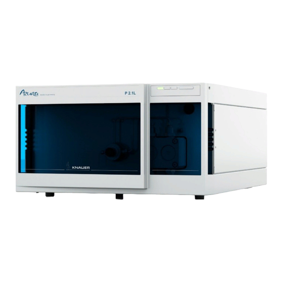
ƒ Prolonged operating time because of the automatic piston ƒ backflush ing Leak management ƒ Options KNAUER offers the following accessories: Stainless-steel pump heads ƒ Titanium pump heads for biocompatible applications ƒ Display software Mobile Control ƒ Heating/cooling elements for the pump head ƒ... - Page 15 Product information Legend Status LEDs Pump head Pressure sensor Fig. 1: Pump P 2.1L front view Legend Left LED Center LED Right LED Standby switch 1 2 3 Fig. 2: LEDs and switch on the front of the device Legend Serial number Pin header LAN port...
-
Page 16: Pump Heads
Even small quantities of other substances, such as additives, modifiers, or salts can influence the durability of the materials. Note: The solvent list contains the solvents KNAUER recommends for use. If there is any doubt, contact the Technical Support of the manufacturer. - Page 17 Product information Suitable solvents Acetone at 4 °C–25 °C (39.2 °F–77.0 °F)1 ƒ Acetonitrile2 ƒ Benzene ƒ Dilute acetic acid (e.g. 10–50 %) at 25 °C/77.0 °F ƒ Dilute ammonia solution ƒ Dilute sodium hydroxide (1 M) ƒ Ethanol1 ƒ Ethyl acetate ƒ Hexane/heptane at 4–25 °C (39.2–77.0 °F)1 ƒ Isopropanol ƒ...
-
Page 18: Meaning Of The Leds
Product information Meaning of the LEDs There are three LEDs and a standby switch on the front of the device. Fig. 4: LED panel when the device is switched off The LEDs show different colors depending on the operating status. Color Operating condition Operation... -
Page 19: Symbols And Signs
Product information Standby To activate the standby, keep the switch pressed for 5 seconds. Note: Malfunctioning system after repeated standby possible. After repeatedly using the standby, switch off the power switch and back on again, to reset the data storage. Symbols and signs The following symbols and signs can be found on the device: Symbol Meaning... -
Page 20: Installation And Initial Startup
4. Installation and initial startup Before you determine the operation site, read the chapter “11. Technical data” on page 62. There you will find all device-specific information on power supply, ambient conditions and humidity. Note: The intended use be ensured only if the requirements for ambient conditions of the operating environment are met. -
Page 21: Space Requirements
Country-specific plugs: Before switching on the device, check wheth- ƒ er the supplied plug is approved for your country. Overview of the device- and country-specific plug types from KNAUER: www.knauer.net/plugs Power strips: If several devices are connected to one power strip, ƒ... -
Page 22: Connecting The Piston Backflushing
Mixture of 80 % ethanol and 20 % water or higher ethanol content ƒ Mixture of 80 % isopropanol and 20 % water or higher isopropanol ƒ content Note: KNAUER recommends the use of pure isopropanol as flushing solu tion for piston backflushing. AZURA® Pump P 2.1L Instructions V6840... -
Page 23: Eluent Inlet
Installation and initial startup Note: Never fill the backpiston flushing with normal phase solvents like heptan or hexan. Note: Fluctuations in the level of the back piston cylinder may indicate a problem with the seals or connections of the pump head. Component defect Possible damage to the pump head due to over-tightened capillary fitting. -
Page 24: Connecting The Eluent Inlet To The Pump Head
Installation and initial startup 4.5.1 Connecting the eluent inlet to the pump head Process Figure Procedure 1. With the knurled-head screw , screw the eluent inlet into the inlet screw fitting of the pump head. 2. Turn the eluent inlet until the intake manifold input points forward. -
Page 25: Changing The Setup To Lpg
Installation and initial startup Process Figure Procedure 1. Push the Teflon hose directly on the olive-type tube fitting Pump head: 1000 ml ƒ 2. Fasten the Teflon hose with a hose clamp. Fig. 12: Eluent line on 1000 ml pump head Next steps Check whether the connectors and lines are tight. -
Page 26: Mounting The Valve Block
Installation and initial startup 4.6.1 Mounting the valve block Prerequisite The pump has been switched off. ƒ The power plug has been pulled. ƒ Tool Open-end wrench, size 17 ƒ Torque wrench ƒ Note: Always place seals in pairs on both fastening screws. Process Figure Procedure... -
Page 27: Connecting The Eluent Line To The Pump Head
Installation and initial startup 4.6.2 Connecting the eluent line to the pump head Process Figure 1 2 3 Procedure 1. Push the Teflon hose through the fastening screw and the cutting ring 2. Insert the hose end as far as possible into the eluent inlet fit ting of the pump head. -
Page 28: Priming The Pump
Installation and initial startup Priming the pump Prerequisite The capillaries have been connected. Tool Syringe Column defect Damage to the column due to purging. Open the venting screw. Remove the column. Note: Before the pump can be used, it must be primed. Process Figure Procedure... -
Page 29: Leak Management
Installation and initial startup Leak management The leak management consists of the leak sensor and the drainage sys- tem (funnels, hoses, nozzles). The drainage system ensures that escaping liq uids flow into a waste bottle. When leaks are registered by the leak sen sor, the LED flashes red. -
Page 30: Control
Remote connector Fig. 24: Connectors on rear side Note: HPLC devices from KNAUER only work with IP addresses, which have been assigned by IPv4. IPv6 is not supported. Note: When using PurityChrom®, static IP addresses are needed (see section „4.10 Setting IP addresses via software“on page 27). -
Page 31: Configuring Lan Settings
Installation and initial startup Next steps Configure LAN properties (see section „4.9.2 Configuring LAN set- tings“on page 25). 4.9.2 Configuring LAN settings The LAN uses only one server (which is normally the router) from that the devices automatically receive their IP address. Prerequisites In Windows, power saving, hibernation, standby, and screen saver ƒ... -
Page 32: Configuring The Router
26). 4.9.4 Configuring the router The router is preset at the factory. Information about address, user name and password is noted in the router manual: www.knauer.net/router. Process Procedure 1. To open the router configuration, start your Internet browser and enter the IP address (does not apply for all routers). -
Page 33: Controlling Several Systems Separately In Lan
Installation and initial startup Process Procedure 1. Make sure that there is no overlap between the IP addresses of the router and the corporate network. 2. In case of an overlap, change the IP address range of the router. 3. Use the patch cable to connect the router WAN port to the compa- ny network. -
Page 34: Mobile Control: Setting A Dynamic Ip Address Via Device Name
Installation and initial startup Prerequisites The device is switched on. ƒ Mobile Control is installed and running. ƒ The connection between Mobile Control and the device has been ƒ established. Process Procedure 1. In Mobile Control, click <Settings>. 2. On the <General> tab, choose the device name. 3. -
Page 35: Mobile Control: Setting A Dynamic Ip Address Via Device Serial Number
Installation and initial startup IP address mode Fig. 27: Network settings for dynamic IP address Result The device is now accessible via a dynamic IP address. 4.10.3 Mobile Control: Setting a dynamic IP address via device serial number Prerequisites The device is switched on. ƒ... -
Page 36: Firmware Wizard: Setting A Static Ip Address
Installation and initial startup 4.10.4 Firmware Wizard: Setting a static IP address Note: More information about LAN settings can be found in the Mobile Control Software Instructions in the chapter "Firmware Wizard” (document no. V6851-2). Text box for serial number of the device Setting IP address manually... - Page 37 Installation and initial startup Process Procedure 1. In Firmware Wizard, cleck <Reset LAN Settings...>. 2. The window <Device connection settings> opens. Enter serial number of the device into the text field <Target device serial number> 3. Select option <Obtain an IP address automatically> 4.
-
Page 38: Remote Control
Installation and initial startup 4.11 Remote control 4.11.1 Connector assignment Remote terminal strip For receiving start, control, and error signals from external devices ƒ For sending start, control and error signals to external devices ƒ Fig. 30: Remote terminal strip Signal Explanation Analog... - Page 39 Installation and initial startup Signal Explanation Provides a voltage of 5 V with respect to GND. This makes it possible to supply a consumer that is switched by an EVENT. Protection: 5 V–50 mA Reference point of the voltage at the signal inputs. Events remote connector For test purposes or in some other cases, it can make sense to manually enter these signals:...
- Page 40 Installation and initial startup Assignment Connection Function TTL output Levels: passive 0 V ƒ active 5 V ƒ Pulse: 5 V for at least 1000 ms ƒ Reference point of the voltage at the signal inputs. 4TTL TTL-compatible output Levels: passive 0 V ƒ active 5 V ƒ...
- Page 41 Installation and initial startup Assignment Connection Function Relay Contact The contact is on a floating basis. Its setting depends on the settings in the software. Steady-rate signal: passive = open relay contact ƒ active = closed relay contact ƒ Pulse: Closed relay contact for at least 1000 ms ƒ...
-
Page 42: Connecting The Pin Header
Installation and initial startup 4.11.2 Connecting the pin header To control one device through another, the pin header is used. To use remote control, you have to connect cables to the pin header. The single ports are used to exchange control signals. Prerequisites The device is switched off. -
Page 43: Analog Control
Installation and initial startup 4.12 Analog control Note: Contact the customer support to change the default settings and to select the analog control. Analog ports serve for exchanging analog control signals. Reference point for the signals is the connector GND. OUT: Device sends signal. -
Page 44: Operation
If the device is part of an HPLC system, note the following: The network connection to the router is established ƒ The chromatography software has been installed by KNAUER or a ƒ com pany authorized by KNAUER. The capillaries have been connected. -
Page 45: Purging The Pump
Operation Purging the pump Before the pump can be used, it must be purged to remove excess air in the capillaries. Purge the pump in the following cases: At initial startup to eliminate air bubbles in hoses and capillaries. When is flushing ƒ... -
Page 46: Switch-On
Operation Process Figure Procedure 1. Insert the inlet hoses into the storage containers and start the pump with an intermediate flow rate. 2. As the pump is self-pri- ming, the venting screw the pressure sensor can be opened. 3. If necessary, draw liquid through the dry feed hoses to the pump head with the provi- Fig. -
Page 47: Software Control
Software control There are several options for controlling the device: with chromatography software ƒ with KNAUER Mobile Control ƒ Note: It is not possible to use two control methods simultaneously. If the device is connected to the software, it cannot be controlled via Mobile Control. -
Page 48: Switch-Off
Operation Switch-off If you want to switch off the pump for a longer term, purge the pump head with isopropanol. Prerequisite The pump has been purged (see „5.2 Purging the pump“ on p. 39). Use isopropanol if you are going to take the device out of operation for a longer period of time or if you want to prepare it for storage. -
Page 49: Functionality Tests
The customer can request the Installation Qualification. In case of a request, the Technical Support of KNAUER or a provider authorized by KNAUER performs this functionality test during the installation. The IQ is a standardized document and includes the following: Confirmation of flawless condition at delivery ƒ... -
Page 50: Device Data
Functionality tests 6.1.5 Device data Device name Product no. Firmware Serial number version: Location Device manu- KNAUER Wissenschaftliche Geräte GmbH Phone : +49 30 809727-111 facturer/ Hegauer Weg 38, 14163 Berlin E-Mail: support@knauer.net supplier KNAUER agent 6.1.6 Customer data Customer Customer no. -
Page 51: Initial Startup
Comments/recommendations 6.1.10 Change list Description of Additional information Date/signature deviation 6.1.11 Certificate A KNAUER employee or an employee authorized by KNAUER has che- cked the device and performed all tests described in the IQ. AZURA® Pump P 2.1L Instructions V6840... -
Page 52: Operation Qualification (Oq)
The test intervals depend on the usage of the device. Execution The test can be carried out either by the Technical Support of KNAUER or from a provider authorized by KNAUER (for a fee). AZURA® Pump P 2.1L Instructions V6840... -
Page 53: Troubleshooting
7. Troubleshooting First measures: Check all cables and fittings. ƒ Check if air has got into the supply lines. ƒ Check the device for leakages. ƒ Further measures: Compare occurring errors with the list of possible errors (see below). ƒ Contact the Customer Support. -
Page 54: Possible Problems And Solutions
Troubleshooting Possible problems and solutions Problem Solution Device cannot be swit- Inspect the power cable to ensure that it ched on. is plugged into the power supply. When purging, the Check if the venting screw on the pres- pump switches off. sure sen sor is turned up. -
Page 55: Error Messages
Troubleshooting Error messages If other error messages are displayed besides those listed below, please restart the device. Inform the Technical Support of the manufacturer in case the error message displays repeatedly. Message Solution Auto pump head type: Switch the device off and on. ƒ... - Page 56 Troubleshooting Message Solution Cannot initialize LAN Check cables and connections in local area net work. Cannot operate with an Create a link. empty link Cannot purge during the End method and start purging. run! Cannot read data from Switch the device off and on. Inform the FRAM Techni cal Support of the manufacturer in case the sys tem message repeats itself.
- Page 57 Troubleshooting Message Solution Link is loaded First unload the link then change the link or delete it. Link is running Wait until the link has been completed, then change the link or delete it. Max. flow limit reached Confirm, pump continues running Maximum pres sure! Sys- Reduce the pressure or adjust the ƒ...
- Page 58 Troubleshooting Message Solution Too many lines in Check the number of program lines. program A maximum of 100 program lines are possible. Unable to attain min. Confirm, pump continues running flow set point Unknown pump head Check the pump head. ƒ...
-
Page 59: Maintenance And Care
8. Maintenance and care Organic solvents are toxic above a certain concentration. Ensure that work areas are always well-ventilated! When performing maintenance tasks on the device, always wear safety glasses with side protection, pro- tective gloves, and an overall. All wetted components of a device, e. g. flow cells of detectors or pump heads and pressure sensors for pumps, have to be flushed with isopropa- nol first and water afterwards before being maintained, disassembled or disposed. -
Page 60: Pump Head
Maintenance and care Pump head Depending on the requirements of the user, different pump heads are used (see „13.2 Pump heads with accessories“, p. 69). 8.3.1 Screw fittings on the pump head Legend Capillary fitting Allen screws Outlet fittings Inlet fittings Eluent Inlet Fig. - Page 61 Maintenance and care Process Figure Procedure 1. To remove the capillary, loosen the capillary screw fittings at the pump head outlet and pressure sensor inlet. 2. Disconnect the hoses of the piston backflushing from the flush pump and the pump head.
-
Page 62: Attaching Capillaries To The Pump Head
Maintenance and care 8.3.3 Attaching capillaries to the pump head Component defect Possible damage to the pump head due to over-tightened capillary fitting. Note the torque of the screw connection. Pay attention to the torques in the chapter „8.4 Check valves“ on page Prerequisite The pump head has been removed. -
Page 63: Check Valves
Maintenance and care Check valves Dirty check valves do not open and close properly. They cause pressure fluctuations and irregular flow. If it is impossible to clean the check valves, replace the whole unit. Pump head stainless steel Torque for inlet and outlet fitting Torque 100 ml 15 Nm... -
Page 64: Installing The Check Valves
Maintenance and care Process Procedure 1. Place each check valve into a beaker with solvent, e.g. isopropanol. 2. Put the beaker with the check valve in an ultrasonic bath for at least 10 minutes. 3. Let the check valves dry afterwards. Next step Insert both cleaned check valves. -
Page 65: Transport And Storage
Do not hold onto front cover or leak tray, as these parts are loosely attached to the device. Transporting the device Documents: If you want to return your device to KNAUER for repairs, ƒ enclose the „Service request form and decontamination report“which... -
Page 66: Storing The Pump Head
Transport and storage 9.4.1 Storing the pump head Device defect Residuals chemicals can damage the pump head if they are not being removed before storage. For reuse, fl ush the pump head and fi ll it with isopropanol. Before storage, seal the inlets and outlets with cap fi ttings. If you want to store pump heads separately, proceed as follows: Prerequisite The pump head has been dismounted (see chapter “8.3.2 Dismounting... -
Page 67: Disposal
160214. 10.2 WEEE registration number KNAUER as a company is registered by the WEEE number DE 34642789 in the German “Elektroaltgeräteregister” (EAR). The number classifies to category 8 and 9, which, among others, comprises laboratory equipment. -
Page 68: Technical Data
11. Technical data 11.1 Main features Pump type Preparative HPLC pump Delivery system Dual-piston pump Flow rate range 100 ml pump head: ƒ • 0.01 - 100 ml/min • 1 - 80 ml/min (recommended) • 1 - 40 ml/min (continous working) 250 ml pump head: ƒ... -
Page 69: Communication
Technical data Gradient support Isocratic HPLC pump ƒ Pump with binary or ternary LPG valve block ƒ (low pressure gradient system, LPG) Up to 4 pumps in combination (high pressure ƒ gradient system, HPG) System protection and P adjustable 11.2 Communication Control ƒ... -
Page 70: Chemical Compatibility Of Wetted Materials
The following list contains information about the chemical compatibility of all wetted materials which are used in devices made by KNAUER. The data bases on a literature research on the manufacturer specifications of the materials. The wetted materials of this device are listed in the chapter “Technical data”. - Page 71 Chemical compatibility of wetted materials Polyimide (Vespel®) This material is wear-resistant and permanent resilient thermically (up to 200 °C) as well as mechanically. It is chemically broadly inert (pH range 1-10) and is especially resistant against acidic to neutral and organic solvents, but vulnerable to pH strong chemical or oxidizing environments: It is incompatible with concentrated mineral acids (such as sulfuric acid), glacial acetic acid, DMSO and THF.
-
Page 72: Non-Metals
Chemical compatibility of wetted materials Polychlortrifluorethylene (PCTFE, Kel-F®) The semi-crystalline thermoplastic material is plasticizer-free and dimen- sionally stable, even in a wide temperature range (−240 °C to+205 °C). It is moderately resistent against ether, halogenated solvents and toluene. Halogenated solvents over +60 °C and chlorine gas should not be used. Fluorinated rubber (FKM) The elastomer consisting of fluorinated hydrocarbon stands out due to a high resistance against mineral oils, synthetic hydraulic fluids, fuels,... -
Page 73: Metals
Chemical compatibility of wetted materials Mineral wool This insulating material consists of glass or stone wool fibres and isolates in high oxidizing conditions and at high temperatures. Mineral wool is valid as commonly inert against organic solvents and acids. Glass, glass fibre, quartz, quartz glass These mineral materials are resistant against corrosion and wear and are mostly chemical inert. -
Page 74: Repeat Orders
For reorders of spare parts use the enclosed packing list. Contact the Technical Support in case there are any questions on spare parts or acces sories. Further information Further information on spare parts and accessories can be found online: www.knauer.net. 13.1 Device and accessories Name Order no. -
Page 75: Pump Heads With Accessories
Repeat orders 13.2 Pump heads with accessories Name Order no. Pump heads Pump head, 100 ml, stainless steel A4029-1 Pump head, 100 ml, titanium A4029V2 Pump head, 250 ml, stainless steel A4021-1 Pump head, 250 ml, titanium A4021V2 Pump head, 500 ml, stainless steel A4038-1 Pump head, 500 ml, titanium A4038V2 Pump head, 1000 ml, stainless steel... - Page 76 Latest KNAUER instructions online: www.knauer.net/library KNAUER Phone: +49 30 809727-0 Wissenschaftliche Geräte GmbH Fax: +49 30 8015010 Hegauer Weg 38 E-Mail: info@knauer.net 14163 Berlin Internet: www.knauer.net © KNAUER 2021...
Need help?
Do you have a question about the Azura P 2.1L and is the answer not in the manual?
Questions and answers