Table of Contents
Advertisement
Quick Links
Advertisement
Chapters
Table of Contents

Subscribe to Our Youtube Channel
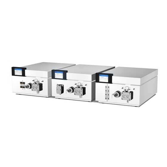
Related Manuals for Knauer BlueShadow Pump 40P


Summary of Contents for Knauer BlueShadow Pump 40P
- Page 1 BlueShadow Pump 40P Service manual V7615A HPLC...
-
Page 2: Table Of Contents
Table of Contents Table of Contents Safety for service technicians ........Protective measures . - Page 3 Table of Contents Spare parts ..........Pump head .
-
Page 4: Safety For Service Technicians
Safety for service technicians Safety for service technicians The installation manual is an addition to the existing system man- ual that includes all work that requires the installation of certain subasemblies or the opening of a device's housing. Checking intended use Only use the device for applications that fall within the range of the intended use. -
Page 5: Protective Measures
Safety for service technicians Protective measures The following applies for all repairs on the device: Hazard symbol Warning instructions DANGER! Danger of electric shock! Switch off power supply! Pull the power plug! DANGER! Danger due to toxic, caustic or radioactive substances due to con- tamination of the device.... -
Page 6: What Is Maintained Or Repaired
What is maintained or repaired? What is maintained or repaired? Measures Hours in operation Check the torque of the screw 1000 fittings Clean the pistons Check ball valves Check the drive 5000 Check the tension of the toothed belt ... -
Page 7: Pump Head Repair
Pump head repair Pump head repair WARNING! Aggressive or toxic solvent residue can irritate the skin! Wear protective gloves! In case of a malfunction or as part of routine maintenance, the pump head can be disassembled into individual parts. During this procedure, seals, guide discs, springs or pistons can be replaced. -
Page 8: Removing The Pump Head
Pump head repair Removing the pump head 1. Remove the tubes from the inlet and outlet of the piston backflushing (A). 2. Remove all tubes from the solvent bottles. 3. Unscrew the eluent line (D). 4. Unscrew the outlet fitting 2 (E) and the inlet fitting of the pressure sensor (F) to remove the capillary. -
Page 9: Removal Of Pump Head
Pump head repair Removal of Pump Head CAUTION! Avoid breaking the piston rods! Before disas- sembly, first remove the two piston rods. Deposit the two piston rods in the correct orien- tation to ensure correct orientation when put- ting them back in. Overview of the pump Figure head parts... - Page 10 Pump head repair Overview of the pump Component Comment head parts Check valve Ball valve with flow in one direction; Made of sapphire/ ruby w/direction of flow indicator Seal Modified Teflon seal Outlet fitting Outlet fitting, side of pump head Capillary connection kit Ø...
-
Page 11: Fig. 2 With The Pump Head Removed At The Back Of The Device, The Components Are Now Visible
Pump head repair Complete disassembly of Procedure Figure the pump head A Piston backflushing 1. Flush the pump head with water or B RFID-Chip isopropanol if the C Piston rod pump head is to be stored. D Piston guide 2. Remove the pump E Feed block head (see manual). -
Page 12: Fig. 4 Parts Of The Piston Guide
Pump head repair Removing the parts of Procedure Figure the piston guide A Low-pressure seal 1. Remove the parts and securely deposit B Washer them in the proper C Compression spring sequence and in the correct orientation. D Bushing E Piston guide F Piston rod Fig. -
Page 13: Fig. 6: Special Tool For Bal Seal® Seal
Pump head repair Replacing seals on the Procedure Figure inner side of the feed block A Special tool for removal 1. Screw the special seal tool into the Bal Seal® seal and B Feed block remove from the feed block. Fig. 6 Special tool for Bal Seal®... -
Page 14: Assembling The Pump Head
Pump head repair Replacing the seals on Procedure Figure the inner side of the piston backflushing A O-Ringe 1. Replace O-rings of the piston backflush- B Low-pressure seal ing. 2. Screw the special tool into the low- pressure seal and remove from the feed block. -
Page 15: Fig. 10: Special Tool For Pressing In The High-Pressure Seal
Pump head repair Pre-forming the seal Procedure Figure from Bal Seal® with the special tool A Special tool for pressing 1. Set the high-pres- in the seal sure seal with the metal washer spring B High-pressure seal pointing out onto the special tool and pre-form the seal. -
Page 16: Fig. 13 Sapphire Ring In Adaptor Ring
Pump head repair Inserting the spacer Procedure Figure A Adaptor ring 1. Insert sapphire ring into adaptor ring and place on seal- ing tool. 2. Using the sealing tool, insert the adap- Fig. 13 Sapphire ring in adaptor tor ring, together ring with the sapphire ring, into the feed... -
Page 17: Fig. 15: Special Tool And Low-Pressure Seal
Pump head repair Pressing the low-pres- Procedure Figure sure seal from Bal Seal® into the piston back- flushing A Low-pressure seal 1. Position the low- pressure seal on the B Special tool special tool. 2. Press fitting seal using special tool. Fig. -
Page 18: Fig. 17: Piston Backflushing With Washers
Pump head repair Positioning the washers Procedure Figure flat and fitting the com- pression springs and bushings A Washers The springs for the pis- ton guide can be posi- B Bushing tioned on the feed C Compression spring block and piston back- flushing, which have been put together. -
Page 19: Fig. 19 Assembling The Piston Guide
Pump head repair Screwing the pump head Procedure Figure together A Piston guide 1. Position piston guide. B Screw 2. Insert screws with C Compression spring Allen wrench. 3. Manually press the piston guide down against the compres- sion springs. 4. -
Page 20: Replacing The Check Valves
Replacing the check valves Dirty check valves may not open and close correctly. The entire check valve is replaced. For replacement of the check valves, KNAUER recommends removing the pump head. Prerequisites • Pump has been flushed with water and isopropanol. -
Page 21: Disassembling The Housing
Disassembling the housing Disassembling the housing It is necessary to open a device's housing for certain maintenance and repair work. Disassembly of the device hood, suitable for certain mainte- nance and repair work on the inside of a device ... -
Page 22: Spare Parts
Disassembling the housing Removing the device Process Figure hood B Device hood 1. Push device hood back. 2. Lift the device hood up and out with both hands. Fig. 23 Removing the device hood Result The device has been opened. Next steps Remove side panels. -
Page 23: Spare Parts
Disassembling the housing Removing the side panel Process Figure A Allen screws 1. Loosen both Allen screws (A) on the B Side panel back of the device. 2. Remove side panel (B), Fig. 24 Loosen fastening screws on the back of the device Result Subassemblies on the left side can now be accessed more easily Next steps... -
Page 24: Replacing The Fan
Replacing the fan Replacing the fan Note the following when repairing the fan: The fan is fastened on the rear panel of the device with fan mountings made of EPDM rubber The fan can be removed from the inside of the device without the use of tools ... -
Page 25: Pulling Out The Fan
Replacing the fan Pulling out the fan 1. Remove the fan power cable from the PIN connector (C). 2. By hand, remove the entire fan out of the rear panel of the device in the direction of the arrow. This is possible without the use of additional tools. -
Page 26: Inserting A New Fan
Replacing the fan Inserting a new fan Note Pay attention to the direction of the fan printed on the fan. One arrow indicates the direction of rotation of the fan, the other indicates the direction in which the air is pulled. Legend A Power supply B Fan with the power... -
Page 27: Removal Of Piston Backflushing Pump
Removal of piston backflushing pump Removal of piston backflushing pump The piston backflushing pump (A) is secured to the fastening plate (C) of the pump subassembly. Fig. 27 Device interior: Piston backflushing pump Prerequisite Pump head has been removed ... -
Page 28: Replacing The Pressure Sensor
Functional principle The pressure sensor is adjusted to the mechanical and electrical properties of the pump with a calibration procedure. The calibration requires a test station from KNAUER and the service software. For better results, the calibration is repeated once. -
Page 29: Removing The Pressure Sensor
Replacing the pressure sensor Removing the pressure sensor The pressure sensor is secured with two screws on the inside of the housing of the pump. Removing the pressure Process Figure sensor 1. Close bleed Exterior view screw (B) (order number: P2719XA). -
Page 30: Installing A New Pressure Sensor
M1368 Replacing the motor Note Replacing the motor of the pump on the inside of the housing is to be performed exclusively by the KNAUER technical service department or a company authorized by KNAUER. Danger of electric shock! WARNING! Switch off the power supply!... -
Page 31: Removing The Motor Of The Pump
Replacing the motor Removing the motor of the pump Removal of the motor Process Figure 1. Disconnect all elec- trical connections of the motor, for instance the control unit for the pulse per revolution (encoder) and the DC power connec- tion. -
Page 32: Fig. 33: Three Phillips-Head Flat-Head Screws
Replacing the motor Removal of the motor Process Figure 3. Only loosen the two screws of the motor mount (C) with a screwdriver (cross- head), do not unscrew them com- pletely. This removes the tension from the V- belt (D). 4. -
Page 33: Spare Parts
Replacing the motor Tensioning the V-belt Process Figure 1. Turn the drive shaft (C) together with the V-belt to a posi- tion where the upper retaining screw of the motor becomes visible through one of the openings (B) of the drive shaft 2. -
Page 34: Replacement Of The Mainboard
Replacement of the mainboard Replacement of the mainboard Practical tip Not all plug connections on the mainboard are designed confusion-proof. Mark the cable before removing it. Legend A Power supply B Mainboard C Piston backflushing pump D Pump E Motor F Fan ... -
Page 35: Replace Mainboard
Replacement of the mainboard Replace mainboard Danger of electric shock! WARNING! Switch off the power supply! Pull the power plug! Caution! Electrostatic discharge can destroy the electronics! Wear protective bracelet against electrostatic discharge and ground. Fig. 36 Edge connector with snap lock ... -
Page 36: Mainboard Types And Configuration Of The Plug Connectors
Replacement of the mainboard Mainboard types and configuration of the plug connectors Pump A Rear wall of device B Fan, possibly doubled C Power supply D Pressure sensor E Display F RFID G Motor DC connection H Hall sensor I Flush pump J Manager connection Fig. -
Page 37: Removing The Power Plug
Replacement of the mainboard Removing the power plug Prerequisite The housing has been opened. Procedure Procedure for removing the power supply: Disconnect all electrical power supply connections Remove cover of the power supply Remove printed circuit board of the power supply ... -
Page 38: Spare Parts
Replacement of the mainboard Removing the power Process Figure plug A Power supply 1. Loosen all cable connec- tions at the power sup- B Allen screws ply. C Power input 2. Remove 4 Allen screws (B). 3. Remove power supply (A). Fig. -
Page 39: Tightening Torque For Screws
Tightening torque for screws Tightening torque for screws Practical tip The use of a dynamometric screwdriver for the tightening torques is highly recommended. Screws in materials made of metal The following materials are considered metal: Aluminum Steel, stainless and other ... -
Page 40: Screws In Materials Made Of Plastic
Troubleshooting Screws in materials made of plastic The following materials are considered plastic: PEEK PETP PMMA PTFE Size Tightening torque (in Nm) Troubleshooting Error list In the following list, the error numbers with the associated indexes are listed that appear on the display if an error occurs. - Page 41 Troubleshooting Error number Index Error_22 12C Init failed Error_23 Cannot read RTC Error_24 12C operation failed Error_25 Cannot write data on FRAM Error_26 Cannot read data from FRAM Error_27 Instrument remote controlled Error_28 Error input activated Error_29 Time already exists Error_30 Too many lines in program Error_31...
- Page 42 Troubleshooting Error number Index Error_53 Cannot start time table Error_54 Time table is not active Error_55 Time table is not loaded Error_56 No gradient is available in isocratic mode Non-existing component is set to Error_57 non-0 value Error_58 Sum of components is not 100. Error_59 Maximum pressure! System stopped Error_60...
-
Page 43: Possible Problems And Rectifications
Troubleshooting Possible problems and rectifications In the following table, approximately 90% of the problems that occur in practical use are listed with possible solutions. Problem Cause Solution Instable Malfunction Clean the ball pressure, of ball valve valves instable flow ... - Page 44 Troubleshooting Problem Cause Solution Pump can only Keyboard, Replace door with be controlled display or control panel using the touchscreen computer, not from the device control panel Managers The supply Replace cannot be voltage with connection cable controlled even 24 V is not of manager pump...
-
Page 45: Spare Parts
Spare parts Spare parts Pump head 10 ml stainless steel G2712 P3708 P6116A R0458 G0926 Fig. 42 Pump head, 10 ml, stainless steel Order number Name E3111 Pump head G0563 Check valve G0926 Capillary connection G2712 Backflushing fitting M1310 High pressure seal M1371 O-ring M1458... -
Page 46: Fig. 43 Pump Head, 10 Ml, Titanium
Spare parts Pump head 10 ml titanium – order number C56351.0 G2712 P3708 P6116A R0458 G0926 Fig. 43 Pump head, 10 ml, titanium Order number Name E3121 Pump head G0563 Check valve G2712 Backflushing fitting M1310 High pressure seal M1371 O-ring M1458 Low pressure seal 1/8''... -
Page 47: Fig. 44 Pump Head, 50 Ml, Stainless Steel
Spare parts 50 ml Pump head, stainless steel – order number C56213.0 Fig. 44 Pump head, 50 ml, stainless steel Order number Name E3112 Pump head 50 ml G0563 Check valve G2712 Backflushing fitting N0202A Backup ring P2712-1 Piston rod 1/4'' P6117 Piston guide R0462... -
Page 48: Fig. 45 Pump Head, 50 Ml, Titanium
Spare parts 50 ml Pump head, titanium – order number C56211.0 Fig. 45 Pump head, 50 ml, titanium Order number Name E3131 Pump head G0563 Check valve G2712 Backflushing fitting M1371 O-ring N0202A Backup ring P2712-1 Piston rod 1/4'' P6117 Piston guide R0462 Pressure spring... -
Page 49: Devices
Spare parts Devices Fig. 46 Devices Order number Name P6503 Side panel P6505 Device hood Fig. 47 Order number Name G5026 M0984 Fan fastener... -
Page 50: Pressure Sensor
Spare parts Pressure sensor Order number Name G2703V1 Pressure sensor, complete G2704 Bushing M1368 O-ring P2719XA Ventilation screw P7015 Sealing ring, PTFE P7022 Sealing ring, PEEK Drive Order number Name G2719-1 Conductor, complete G2721-1 Toothed wheel, complete... -
Page 51: Motor
Spare parts Motor Order number Name G2718-2 Pump engine M1840 Tooth belt Boards Order number Name G1153XA RFID modul G1156XB Mainboard G1595 Hall sensor... -
Page 52: List Of Figures
List of Figures List of Figures Fig. 1: Rear view of a complete UHPLC pump head ....10 Fig. 2: With the pump head removed at the back of the device, the components are now visible . - Page 53 List of Figures Fig. 41: Power supply without cover ......39 Fig.
- Page 54 © Wissenschaftliche Gerätebau Dr. Ing. Herbert Knauer GmbH All rights reserved. The information in this document is subject to change without prior notice. Translation of the original German edition of this manual. 2011-10-31 Printed in Germany. www.knauer.net HPLC · SMB · Osmometry Wissenschaftliche Gerätebau...
Need help?
Do you have a question about the BlueShadow Pump 40P and is the answer not in the manual?
Questions and answers