Table of Contents
Advertisement
Quick Links
Advertisement
Table of Contents

Subscribe to Our Youtube Channel
Related Manuals for Knauer Azura P 2.1L


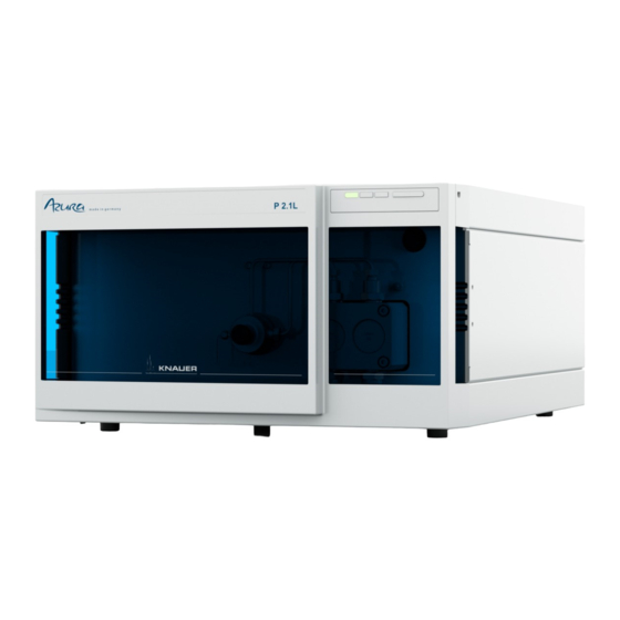
Summary of Contents for Knauer Azura P 2.1L
- Page 1 Pump P 2.1L User Manual V6840 HPLC...
-
Page 2: Table Of Contents
Table of Contents Table of Contents Note For your own safety, read the manual and always observe the warnings and safety information on the device and in the manual! Intended Use ............. . Device Overview . - Page 3 Table of Contents Computer Control ............. Configuring the LAN settings .
-
Page 4: Intended Use
Intended Use Intended Use Note: Only use the device for applications that fall within the range of the intended use. Otherwise, the protective and safety equipment of the device could fail. Device Overview P 2.1L is a self-priming pump with automatic piston backflushing that is used in preparative HPLC systems. -
Page 5: Features
P 2.1L offers the following features: Self-priming pump Prolonged operating time because of the automatic piston backflush- Leak management Options KNAUER offers the following accessories: Stainless-steel pump heads titanium pump heads for biocompatible applications Display control ... -
Page 6: Pump Heads
Even small quantities of other substances, such as additives, modifiers, or salts can influence the durability of the materials. Note: The solvent list contains the solvents KNAUER recommends for use. If there is any doubt, contact the Technical Support of the manufacturer. -
Page 7: Scope Of Delivery
Participation during an installation of a device or a training by the com- pany KNAUER or an authorized company. If you do not belong to this or a comparable professional group, you may not perform the work described in these instructions under any circum- stances. -
Page 8: Where Is Use Of The Device Prohibited
Take the device completely out of operation by either switching off the power switch or by pulling the power plug. Opening the device The device may be opened by the KNAUER Technical Support or any company authorized by KNAUER only. Warning notifications Possible dangers related to the device are divided into personal and material damage in these instructions. -
Page 9: Decontamination
Decontamination Report Devices without a completed Decontamination Report will not be repaired. If you would like to return a device to KNAUER, make sure to enclose a completed Decontamination Report with the device: http:// www.knauer.net/en/knowledge/downloads/service.html... -
Page 10: Transport
Only the supplied power cable is to be used to connect the device to the mains supply. Replace defective power cables only with accessories from KNAUER. Only use power cables with a permission for use from your country. Power plug Make sure that the power plug on rear of the device is always accessible, so that the device can be disconnected from the power supply. -
Page 11: Connecting The Piston Backflushing
Mixture of 80 % water and 20 % ethanol Isopropanol Note: KNAUER recommends the use of pure isopropanol as flushing solu- tion for piston backflushing. Device defect Damage to the pump head caused by overtightened capillary fittings. ... -
Page 12: Eluent Inlet
Installation Procedure Process Figure 1. Use the first hose to connect the inlet of the flush pump to the bottle containing the flush- ing solution. 2. Lead a tube from the flush pump's outlet to the pump head's inlet and fasten. 3. -
Page 13: Changing The Setup To Lpg
Installation Note: If connecting a pump head from 100 – 500 ml, make sure that the tapered side of the cutting ring is pointed towards the fastening screw of the Teflon tube. Procedure Process Figure Pump head: 1. Push the Teflon hose through the fastening screw ... -
Page 14: Mounting The Valve Block
Installation Mounting the Valve Block Prerequisite The pump has been switched off. The power plug has been pulled. Tool Open-end wrench, size 17 Torque wrench Note: Always place seals in pairs on both fastening screws. Procedure Process Figure 1. -
Page 15: Bleeding The Pump
Installation 3. Tighten the fastening screw by hand. 4. Plug a cap fitting into the unused inlet. Fig. 18 Inlets of the valve block Next steps Connect the plug of the valve block. Bleeding the Pump Prerequisite The capillaries have been connected. Tool Syringe Column defect... -
Page 16: Remote Control
Installation Process Figure 2. Push the long ending of the first nozzle into the hose Fig. 21 Hose and nozzle 3. Connect the nozzle and the fun- nel. 4. Push the other end of the hose onto the nozzle of the leak tray. -
Page 17: Remote Terminal Strip
Installation Remote Terminal Strip For receiving start, control, and error signals from external devices For sending start, control and error signals to external devices Legend Display Events Remote Con- nector Fig. 25 Remote terminal strip Signal Explanation ANALOG: Analog output signal. - Page 18 Installation Activating 500 ms pulses Legend Display Events Remote Con- nector Events Fig. 26 Relation between display and terminal strip Assignment Connection Function 1TTL TTL-compatible output Levels: passive 0 V active 5 V Pulse: 5 V for at least 1000 ms 2TTL TTL-compatible output Levels:...
- Page 19 Installation Assignment Connection Function TTL output Levels: passive 0 V active 5 V Pulse: 5 V for at least 1000 ms Reference point of the voltage at the signal inputs. Relay contact The contact is on a floating basis. Its setting depends on the settings in the Control Unit or software.
-
Page 20: Connecting Cables To The Terminal Strip
Installation Assignment Connection Function Error OUT TTL output Levels: passive 5 V active 0 V Error IN TTL input Low active Secure switching threshold at least 10 mA After receiving a signal (short-circuit to ground) from an external device, an error message appears and the device stops. -
Page 21: Computer Control
Fig. 27 P 2.1L rear view Note: HPLC devices made by KNAUER work only with IP adresses which are assigned via IPv4. IPv6 is not supported. This section describes how to set up an HPLC system in a local area net- work (LAN) and how a network administrator can integrate this LAN into your company network. -
Page 22: Connecting The Cables
Installation Properties 5. Click on the button 6. Check the settings in the tab General . The correct settings for the DHCP client are: Obtain IP address automatically Obtain DNS server address automatically 7. Click on the button Connecting the cables A router has several LAN ports and one WAN port... -
Page 23: Controlling Several Systems Separately In A Lan
Installation 2. In case of an overlap, change the IP address range of the router. 3. Use the patch cable to connect the router WAN port to the company network. 4. Restart all devices, including the computer. Controlling several systems separately in a LAN Devices connected to a LAN communicate through ports, which are part of the IP address. - Page 24 Installation Prerequisites The device has been switched on. Mobile Control has been installed and started. The connection between the Mobile Control and the device has been established. Settings> Procedure 1. In the Mobile Control, choose < General 2.
-
Page 25: Firmware Wizard: Setting An Ip Address To Dhcp
Operation 3. Select option <Use the following IP address> 4. Enter the IP address into the text field <IP address> 5. Optionally, adjust subnet mask and gateway 6. Click <Reset Conn. Settings> to accept changes. 7. Restart the device (recommended). Result The device is now accessible via the static IP address. -
Page 26: Switching On The Pump
Operation Component defect cor- Damage to the pump head in case running-in procedure was not performed rectly. Set the correct backpressure and flowrate for the running-in procedure of the pump head. Specific running-in parameters and the general procedure can be found in the supplement „Running-in procedure for pump heads (V6894)“. -
Page 27: Control
Operation Before turning off, if you do not plan to restart the device within shortly. Use the solvent for flushing that is to be used in the subsequent applica- tion. Note: If you used a buffer solution, pay attention to choosing a solvent for flushing in which the buffer solution is soluble. -
Page 28: Functionality Tests
Installation Qualification The customer may request the Installation Qualification, which is free of (IQ) charge. In case of a request, the Technical Support of KNAUER or from a provider authorized by KNAUER performs this functionality test during the installation. The Installation Qualification is a standardized document that comes as part of the delivery and includes the following: P 2.1L user manual V6840, version 3.6... -
Page 29: Troubleshooting
The test intervals are dependent on the usage of the device. Execution The test can be carried out either by the Technical Support of KNAUER or from a provider authorized by KNAUER (for a fee). Troubleshooting First measures 1. -
Page 30: Possible Problems And Rectifications
Troubleshooting Can the devices communicate with the computer, even though the router is disconnected from the company network? 5. Turn off all devices, router, and computer. Firstly, switch on the router and wait until its self-test is finished. Secondly, switch on the devices and the computer. ... -
Page 31: System Messages
Troubleshooting System Messages If other system messages are displayed besides those listed below, please turn the device off and then on. Inform the Technical Support of the manu- facturer in case the system message repeats itself. The system messages are in alphabetical order: System message Solution ... - Page 32 Troubleshooting System message Solution Cannot initialize Check cables and connections in local area net- work. Cannot operate Create a link. with an empty link Cannot purge End method and start purging. during the run! Cannot read data Switch the device off and on. Inform the techni- from FRAM cal support of the manufacturer in case the sys- tem message repeats itself.
- Page 33 Troubleshooting System message Solution Line in time table is Edit the program line. empty Link is loaded First unload the link then change the link or delete it. Link is running Wait until the link has been completed, then change the link or delete it. Max.
-
Page 34: Maintenance And Care
Technical Support hotline: European hotline Languages: Available by telephone in German or English: 8 am to 5 pm (CET) Phone:+49-(0)30-809727-111 Fax:+49-(0)30-8015010 E-mail contact: support@knauer.net (manufacturer) P 2.1L user manual V6840, version 3.6... -
Page 35: Maintenance Contract
Maintenance and Care Maintenance Contract The following maintenance work on the device may only be performed by the manufacturer or a company authorized by the manufacturer and is covered by a separate maintenance contract: • Opening the device or removing housing parts Cleaning and Caring for the Device Device defect Intruding liquids can cause damage to the device. -
Page 36: Attaching Capillaries To The Pump Head
Maintenance and Care 1. To remove the capillary, loosen the capillary screw fittings the pump head outlet and pressure sensor inlet. 2. Disconnect the hoses of the piston backflushing from the flush pump and the pump head. 3. Remove the eluent lines from the eluent inlets. -
Page 37: Check Valves
Maintenance and Care Check Valves Dirty check valves do not open and close properly. They cause pressure fluctuations and irregular flow. If it is impossible to clean the check valves, replace the whole unit. Torque Pump head stainless steel Torque for inlet and outlet fitting 100 ml 15 Nm 250 ml... -
Page 38: Technical Data
Technical Data Note: The ball and position of the valves have been harmonized to each other. Insert the valves in the direction of flow! Procedure Process Figure 1. Insert the check valves 2. Manually screw in inlet and out- let fittings and tighten them with a torque wrench and the respective torque. -
Page 39: Accessories And Spare Parts
For reorders of spare parts use the enclosed packing list. Contact the Technical Support in case there are any questions on spare parts or acces- sories. Further information Further information on spare parts and accessories can be found online: www.knauer.net Device and Accessories Name Order no. Pump P 2.1L APE20 Pump P 2.1L with 100 ml pump head stainless steel... -
Page 40: Pump Heads With Accessories
Accessories and Spare Parts Name Order no. Mobile Control license with 10” touchscreen A9607 Mobile Control Chrom license with 10” touchscreen A9608 Mobile Control license A9610 Mobile Control Chrom license A9612 Tablet lock with stand A9615 Tablet lock A9616 Flexible tablet mount A9617 Accessories kit pump AZURA accessories kit... -
Page 41: Legal Information
A warranty seal is attached on some devices. The warranty seal is color- coded. A blue seal is used by the assembly or technical support of KNAUER for devices to be sold. After repair, service technicians stick an orange seal in identical position. If unauthorized persons interfere with the device or the seal is damaged, the warranty claim becomes void. - Page 42 2001), old devices manufactured by KNAUER are marked as waste electri- cal and electronic equipment: 160214. WEEE registration KNAUER as a company is registered by the WEEE number DE 34642789 in the German "Elektroaltgeräteregister" (EAR). The number belongs to category 8 and 9, which, among others, comprise laboratory equipment.
-
Page 43: Index
Index Index Accessories Additives Analog port port (LAN) AVV marking power cable power strip Care Power supply Check valves power supply cleaning Pump head installing Removing the pump head removal Purging the pump Cleaning LPG system Contact data contamination Remote control, see spring strip Control repair ‘Control Unit’... - Page 44 KNAUER Wissenschaftliche Geräte GmbH © All rights reserved. Technical data are subject to change without notice. Please check our website for latest updates and changes. Translation of the original German edition of this manual, version 3.6 Last manual update: 2018/10/02 Printed in Germany on environmentally friendly paper from sustainable forests.
Need help?
Do you have a question about the Azura P 2.1L and is the answer not in the manual?
Questions and answers