
Related Manuals for Lanner NCA-1050


Summary of Contents for Lanner NCA-1050
- Page 1 Network Appliance Platforms Hardware Platforms for Network Computing NCA-1050 User Manual Version: 1.0 Date of Release: 2024-10-24...
-
Page 2: About This Document
- assumed to be qualified in the servicing of computer equipment, such as professional system integrators, or service personnel and technicians. The latest version of this document can be found on Lanner’s official website, available either through the product page or through the Lanner Download Center page with a login account and password. -
Page 3: Contact Information
NCA-1050 User Manual Contact Information Taiwan Corporate Headquarters China Lanner Electronics Inc. Beijing L&S Lancom Platform Tech. Co., Ltd. 7F, No.173, Sec.2, Datong Rd. Guodong LOFT 9 Layer No. 9 Huinan Road, Xizhi District, New Taipei City 22184, Huilongguan Town, Changping District, Beijing... -
Page 4: Federal Communication Commission Interference Statement
NCA-1050 User Manual Acknowledgment Intel® and Intel® Celeron® are trademarks of Intel Corporation or its subsidiaries in the U.S. and/or other countries. Microsoft Windows and MS-DOS are registered trademarks of Microsoft Corp. All other product names or trademarks are properties of their respective owners. -
Page 5: Safety Guidelines
NCA-1050 User Manual Safety Guidelines Follow these guidelines to ensure general safety: Keep the chassis area clear and dust-free during and after installation. Avoid loose clothing or jewelry that could get caught in the chassis. Secure ties, scarves, and roll up sleeves. -
Page 6: Sécurité De Fonctionnement
The installation of this product must be performed by trained specialists; otherwise, a non-specialist might create the risk of the system’s falling to the ground or other damages. Lanner Electronics Inc. shall not be held liable for any losses resulting from insufficient strength for supporting the system or use of inappropriate installation components. -
Page 7: Electrical Safety Instructions
NCA-1050 User Manual Avertissement Équipement de classe I. Ce matériel doit être relié à la terre. La fiche d’alimentation doit être raccordée à une prise de terre correctement câblée. Une prise de courant mal câblée pourrait induire des tensions dangereuses sur des parties métalliques accessibles. -
Page 8: Table Of Contents
NCA-1050 User Manual Table of Contents Chapter 1: Product Overview ............10 Ordering Information ......................... 10 Optional Accessories ........................11 System Specifications ......................... 12 Front Panel ..........................13 Rear Panel ........................... 14 Chapter 2: Motherboard Information ..........15 Jumpers and Connectors ......................16 Chapter 3: Hardware Setup ............. - Page 9 NCA-1050 User Manual Appendix A: LED Indicator Explanations ........74 Appendix B: Enable 2.5GbE LAN Functionality ......76 Appendix C: Terms and Conditions ..........77 Warranty Policy .......................... 77...
-
Page 10: Chapter 1: Product Overview
NCA-1050 User Manual CHAPTER 1: PRODUCT OVERVIEW NCA-1050 is a compact desktop appliance empowered by Intel® Amston Lake Platform. The NCA-1050’s form factor, relatively low power consumption, robust processing capability, and its various I/O ports together make it ideal for edge deployments, branch offices and retail settings. -
Page 11: Optional Accessories
Note: Users are required to purchase an additional card. PoE+ Kit PSF9758-001 PoE+ Power Adapter Kit (PoE Power Control not included) 1U Rackmount Kit for NCA-1050 Rackmount Kit PSF9759-001 (long ear bracket with adapter holder, 2-sided design) Wall Mount Kit... -
Page 12: System Specifications
NCA-1050 User Manual System Specifications Form Factor Fanless Desktop SKU A: Intel® Atom® X7835RE (Amston Lake) Processor Options SKU B: Intel® Atom® X7405C (Amston Lake) SKU C: Intel® Atom® X7203C (Amston Lake) Frequency 1.3GHz/2.2GHz/2.0GHz Platform CPU Cores 8C / 4C / 2C... -
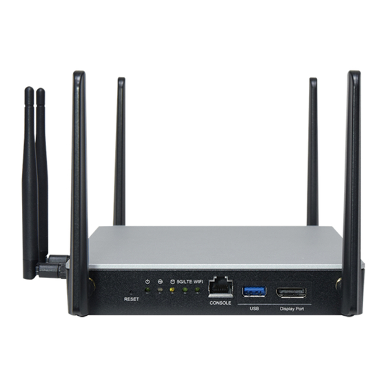
Page 13: Front Panel
NCA-1050 User Manual Front Panel Description Antennas 4x SMA Antenna Holes (Support Wi-Fi/LTE/5G Module) Reset Button 1x Reset Button Power/Status/Storage/ LTE/5G /Wi-Fi, refer to Appendix LED Indicators 2x M.2 LED Indicator (Green color when Wi-Fi/LTE/5G Card Inserted) Console Port 1x RJ45 Console Port USB Port 1x USB 3.0 Port... -
Page 14: Rear Panel
NCA-1050 User Manual Rear Panel Description Antennas 2x SMA Antenna Holes (Support Wi-Fi/LTE/5G Module) Power Button 1x Power Button with LED Power Inlet 1x DC Jack with Lock PoE+ (PSE) Input 1x 4-pin 54V Input Port with Lock (ATX4P) for PoE+ (By Project ONLY) PoE+ Port 1x PoE+ Port (PSE Output 30W;... -
Page 15: Chapter 2: Motherboard Information
NCA-1050 User Manual CHAPTER 2: MOTHERBOARD INFORMATION Block Diagram M.2 2280 SATA USB3.1 Intel Amston Lake... -
Page 16: Jumpers And Connectors
NCA-1050 User Manual Jumpers and Connectors The following references the pin assignments and internal connectors of NCA-1050. - Page 17 NCA-1050 User Manual J3701: 5G Module Setting Description M2B2_OPT_VCC M2B2_P22_VBUS_SENSE M2B2_P20_PCIE_DIS Matching Table of Jumper Settings and Modules below: V = Install Jumper X = NC Latch EM9291 EM9191 Others (1-2) (3-4) (5-6) 80PORT1001: 80 Port Description ESPI_CLK ESPI_IO1 ESPI_RST...
- Page 18 NCA-1050 User Manual JPW1: SATA Power Connector 1x4 Pins 2.54mm Description BIOS1_HOLD BIOS1_CS BIOS1_SO BIOS1_SCK BIOS1_SI JBAT1501 Description VBAT J1501: CMOS Setting Description RTCRST SRTCRST (1-2): Short for Clear RTC and CMOS, NC for Normal Operating (2-3): Normal JSW_SEL5801 (1-2): SW Reset, Default Setting...
- Page 19 NCA-1050 User Manual Description Description +54V +54V J4901 Description POE_RST -54V JUSB4101 Description USB2_DN USB2_DP M2_1 Description Description SATA3_RXP SATA3_RXN SATA3_TXN...
- Page 20 NCA-1050 User Manual LATCH SATA3_TXP LATCH LATCH LATCH LATCH LATCH LATCH LATCH M2_2 Description Description USB2_DP PCIE3_RXP USB2_DN PCIE3_RXN...
- Page 21 NCA-1050 User Manual PCIE3_CLK_P PCIE3_CLK_N PLTRST BT_DIS WIFI_DIS LATCH LATCH LATCH LATCH LATCH LATCH LATCH LATCH PCIE3_TXP PCIE3_TXN WLAN_LED_DET M2_3 Description Description M2B2_P38...
- Page 22 NCA-1050 User Manual F_CARD_POWER_OFF_N (default:1V8) USB2_TXP USB2_TXN LATCH LATCH LATCH LATCH LATCH LATCH LATCH LATCH M2B2_P20_PCIE_DIS M2B2_P22_VBUS_SENSE M2B2_P24 SIM_DETECT USB3_RXN (Default: NC) SIM_RST RESET USB3_RXP M2B2_P68 SIM_CLK SIM_DAT USB3_TXN SIM_VCC 5G_LED_DET USB3_TXP...
-
Page 23: Chapter 3: Hardware Setup
NCA-1050 User Manual CHAPTER 3: HARDWARE SETUP To reduce the risk of personal injury, electric shock, or damage to the system, please remove all power connections to shut down the device completely and wear ESD protection gloves when handling the installation steps. -
Page 24: Installing The System Memory
NCA-1050 User Manual Installing the System Memory The system supports DIMM DDR5 4800MHz non-ECC, and the slots are located on the bottom side of the system. Please follow the steps below to install the DIMM memory module properly. 1. Power off the system. -
Page 25: Installing M.2 Storage Card (Optional)
NCA-1050 User Manual Installing M.2 Storage Card (Optional) The system supports one M.2 2280 B-Key slot for additional data storage. Please follow the steps for installation. 1. Power off the system and open the chassis cover. 2. Locate the M.2 slot on the motherboard. -
Page 26: Installing Wi-Fi Module Card (Optional)
NCA-1050 User Manual Installing Wi-Fi Module Card (Optional) The system supports one M.2 E-Key slot for a Wi-Fi or BT module card. Please follow the steps to install the Wi-Fi module card. Wi-Fi module will require two antennas. The Wi-Fi Module Kit will include:... - Page 27 NCA-1050 User Manual 5. Push down on the module card and secure it with a screw. 6. Next, for thermal pad placement: Remove the protective film surrounding the square thermal pad and gently place it on the underside of the chassis cover, which will be positioned to cover over the Wi-Fi module.
- Page 28 NCA-1050 User Manual 2. From inside the chassis, insert the SMA Bulkhead through the antenna hole on the Bulkhead panel. On the outside of the system, attach the Washer and Nut, and tighten the Nut using an SMA Torque Wrench.
-
Page 29: Installing Lte/5G Module Card (Optional)
NCA-1050 User Manual Installing LTE/5G Module Card (Optional) The motherboard provides one M.2 slot for one LTE/5G module card. Therefore, only one LTE module or one 5G module can be installed. LTE module requires two (2) antennas, and 5G module requires four (4) antennas. - Page 30 NCA-1050 User Manual 6. Push down on the module card and secure it with a screw. LTE Module 5G Module 7. Remove the protective film on the second thermal pad and gently place on the underside of the chassis cover, which will be positioned to cover over the LTE/5G module.
- Page 31 NCA-1050 User Manual 2. From inside the chassis, insert the SMA Bulkhead through the antenna hole on the Bulkhead panel. On the outside of the system, attach the Washer and Nut, and tighten the Nut using an SMA Torque Wrench.
-
Page 32: Installing Sim Card (Optional)
NCA-1050 User Manual Installing SIM card (Optional) The SIM slot on the bottom panel supports the LTE/5G module card. Please follow the steps below for SIM card placement. 1. Power off the system. 2. Turn the system upside down, with its bottom side facing up. -
Page 33: Rackmount The System (Optional)
NCA-1050 User Manual Rackmount the System (Optional) With a rackmount kit, NCA-1050 can be installed into a rack. Please contact Lanner’s sales representative for purchasing the rackmount kit. The rackmount kit contains the following: 1x Rackmount Bracket 5x Zip Ties... - Page 34 NCA-1050 User Manual 3. Then, we place the PoE adapter in the adapter holder section, and secure with two (2) zip ties. Also secure the cables with a zip tie. 4. Attach the power adapter and PoE adapter connector to the system’s rear panel.
-
Page 35: Chapter 4: Bios Setup
BIOS is to identify and initialize processor, memory, hard drives, optical drives, and other hardware. Entering Setup BIOS is a firmware embedded on an exclusive chip on the system’s motherboard. Lanner's BIOS firmware offering including market-proven technologies such as Secure Boot and Intel Boot Guard technology deliver solid commitments for the shield protection against malware, uncertified sequences and other named cyber threats. -
Page 36: Main Page
NCA-1050 User Manual Main Page Setup main page contains BIOS information and project version information. Feature Description BIOS Vendor: American Megatrends Core Version: AMI Kernel version, CRB code base, X64 Compliancy: UEFI version, PI version BIOS Information Project Version: BIOS release version... -
Page 37: Advanced Page
NCA-1050 User Manual Advanced Page Select the Advanced menu item from the BIOS setup screen to enter the “Advanced” setup screen. Users can select any of the items in the left frame of the screen. -
Page 38: Connectivity Configuration
NCA-1050 User Manual Connectivity Configuration Feature Options Description This option configures Connectivity. [Auto Detection] means that if Discrete solution is discovered it will be enabled by default. Otherwise Integrated solution Disable Integrated CNVi Mode (CNVi) will be enabled; Auto Detection [Disable Integrated] disables Integrated Solution. - Page 39 NCA-1050 User Manual Discrete Disabled Serial IO UART0 needs to be enabled to select BT interface Bluetooth Interface Disabled BT Tile Mode Enable/Disable Tile Enabled Disabled Advanced settings Configure ACPI objects for wireless devices Enabled...
-
Page 40: Wwan Configuration
NCA-1050 User Manual WWAN Configuration Feature Options Description Disabled Select the M.2 WWAN Device options to enable 4G - 7360/7560 WWAN Device 4G - 7360/7560 (Intel), 5G - M80 (MediaTek) Modems 5G - M80... -
Page 41: Cpu Configuration
NCA-1050 User Manual CPU Configuration Feature Options Description Disabled Hardware Prefetcher To turn on/off the MLC streamer prefetcher. Enabled Adjacent Cache Disabled To turn on/off prefetching of adjacent cache lines. Line Prefetch Enabled Intel (VMX) Disabled When enabled, a VMM can utilize the additional hardware... - Page 42 NCA-1050 User Manual Efficient-Core Information Performance-Core Information...
-
Page 43: Power & Performance
NCA-1050 User Manual Power & Performance... -
Page 44: Cpu - Power Management Control
NCA-1050 User Manual CPU – Power Management Control Feature Options Description Max Battery Boot performance Select the performance state that the BIOS will set Max Non-Turbo Performance mode starting from reset vector. Turbo Performance Intel (R) Disabled Allows more than two frequency ranges to be... -
Page 45: Gt - Power Management Control
NCA-1050 User Manual GT – Power Management Control Feature Options Description Disabled RC6 (Render Standby) Check to enable render standby support. Enabled Maximum GT frequency limited by the user. Choose Maximum GT between 300MHz (RPN) and 1550MHz (RP0). Value Default Max Frequency... -
Page 46: Pch-Fw Configuration
NCA-1050 User Manual PCH-FW Configuration... -
Page 47: Firmware Update Configuration
NCA-1050 User Manual Firmware Update Configuration Feature Options Description Me FW Image Disabled Enable/Disable Me FW Image Re-Flash function. Re-Flash Enabled... -
Page 48: Trusted Computing
NCA-1050 User Manual Trusted Computing Feature Options Description Enables or Disables BIOS support for security device. O.S. will not Security Device Disable show Security Device. TCG EFI protocol and INT1A interface will Support Enable not be available. Disabled SHA256 PCR Bank... - Page 49 NCA-1050 User Manual Physical Presence Select to Tell O.S. to support PPI Spec Version 1.2 or 1.3. Note Spec Version some HCK tests might not support 1.3. Enables or Disables Platform Hierarchy randomization. DO NOT Disabled ENABLE THIS QUESTION IN PRODUCTION PLATFORMS. THIS IS PH Randomization FOR DEVELOPMENT TESTING.
- Page 50 NCA-1050 User Manual Control PXE Boot Feature Options Description Disabled LAN1 Control PXE Boot LAN2 Control PXE Boot from I210 Lan# LAN3 LAN4...
- Page 51 NCA-1050 User Manual F81804 Super IO Configuration...
-
Page 52: Serial Port 1 Configuration
NCA-1050 User Manual Serial Port 1 Configuration Feature Options Description Disabled Serial Port Enable or Disable Serial Port (COM) Enabled Device Settings IO=3F8h; IRQ=4;... -
Page 53: Hardware Monitor
NCA-1050 User Manual Hardware Monitor Feature Description SYS1 Temp This value reports the System temperature SYS2 Temp This value reports the System temperature (Close to CPU) CPU Temp This value reports the CPU temperature CPU VCORE This value reports the CPU VCORE Input voltage... -
Page 54: Serial Port Console Redirection
NCA-1050 User Manual Serial Port Console Redirection Feature Options Description Disabled Console Redirection Console Redirection Enable or Disable. Enabled... -
Page 55: Console Redirection Settings
NCA-1050 User Manual Console Redirection Settings Feature Options Description Emulation: VT100 ANSI: Extended ASCII char set. VT100+ VT100: ASCII char set. Terminal Type VT-UTF8 VT100+: Extends VT100 to support color, function keys, etc. ANSI VT-UTF8: Uses UTF8 encoding to map Unicode chars onto 1 or more bytes. - Page 56 NCA-1050 User Manual RTS/CTS VT-UTF8 Combo Disabled Enable VT-UTF8 Combination Key Support for ANSI/VT100 Key Support Enabled terminals Disabled With this mode enabled only text will be sent. This is to capture Recorder Mode Enabled Terminal data. Disabled Resolution 100x31 Enables or disables extended terminal resolution.
-
Page 57: Legacy Console Redirection Settings
NCA-1050 User Manual Legacy Console Redirection Settings Feature Options Description Redirection COM Select a COM port to display redirection of Legacy OS and Legacy COM0 Port OPROM Messages 80x24 On Legacy OS, the Number of Rows and Columns supported Resolution... - Page 58 NCA-1050 User Manual PCI Subsystem Settings Feature Options Description Disabled Disables 64bit capable Device Resources to be Allocated in Above 4G Decoding Enabled Above 4G Address Space. Disabled If system has SR-IOV capable PCIe Devices, this option Enables SR-IOV Support Enabled or Disables Single Root IO Virtualization Support.
-
Page 59: Usb Configuration
NCA-1050 User Manual USB Configuration Feature Options Description Enables Legacy USB support. Enabled Legacy USB Auto option disables legacy support if no USB devices are connected. Disabled Support Disabled option will keep USB devices available only for EFI Auto applications. - Page 60 NCA-1050 User Manual Network Stack Configuration Feature Options Description Disabled Network Stack Enable/Disable UEFI Network Stack Enabled Disabled Enable/Disable IPv4 PXE boot support. If disabled, IPv4 PXE IPv4 PXE Support Enabled boot support will not be available. Disabled Enable/Disable IPv4 HTTP boot support. If disabled, IPv4...
- Page 61 NCA-1050 User Manual CSM Configuration Feature Options Description Disabled CSM Support Enable/Disable CSM Support. Enabled...
-
Page 62: Chipset Page
NCA-1050 User Manual Chipset Page Select the Chipset item from the BIOS setup screen to enter the Chipset page. Users can select any of the items in the left frame of the screen. - Page 63 NCA-1050 User Manual System Agent (SA) Configuration Feature Options Description Disabled VT-d VT-d capability Enable Enable IOMMU in Pre-boot environment (If DMAR Control Disable IOMMU table is installed in DXE and If VTD_INFO_PPI is Iommu Enable IOMMU during boot installed in PEI.)
- Page 64 NCA-1050 User Manual PCH-IO Configuration Feature Options Description Power On Restore AC Specify what state to go to when power is re-applied after a Power Off Power Loss power failure (G3 state). Last State...
-
Page 65: Sata Configuration
NCA-1050 User Manual SATA Configuration Feature Options Description Enabled SATA Controller(s) Enable/Disable SATA Device. Disabled SATA Mode Selection AHCI Determines how SATA controller(s) operate. -
Page 66: Security Configuration
NCA-1050 User Manual Security Configuration Feature Options Description Enabled Enable will lock bytes 38h-3Fh in the lower/upper 128-byte bank RTC Memory Lock Disabled of RTC RAM. Enabled Enable/Disable the PCH BIOS Lock Enable feature. Required to BIOS Lock Disabled be enabled to ensure SMM protection of flash. - Page 67 NCA-1050 User Manual TSN GBE Configuration Feature Options Description PCH TSN LAN Enabled Enable/Disable TSN LAN Device. Controller Disabled Enable Timed Enabled Enable/Disable TSN PCS. When enabled, TSN PCS TSN PCS Disabled device will appear in ACPI Table. PCH TSN Port RefClk 38.4Mhz 1Gbps...
-
Page 68: Security Page
NCA-1050 User Manual Security Page Select the Security menu item from the BIOS setup screen to enter the Security Setup screen. Users can select any of the items in the left frame of the screen. Feature Description Setup Administrator If ONLY the Administrator's password is set, it only limits access to Setup Password and is only asked for when entering Setup. - Page 69 NCA-1050 User Manual Secure Boot Feature Options Description Disabled Secure Boot is activated when Platform Key (PK) is enrolled, Secure Boot Enabled System mode is User/Deployed, and CSM function is disabled. Customizable Secure Boot mode: In Custom mode, Secure Secure Boot...
-
Page 70: Key Management
NCA-1050 User Manual Key Management Feature Options Description Disabled Install factory default Secure Boot keys after the platform reset and Factory Key Provision Enabled while the System is in Setup mode Force System to User Mode. Install factory default Secure Boot key... -
Page 71: Boot Page
NCA-1050 User Manual Boot Page Select the Boot menu item from the BIOS setup screen to enter the Boot Setup screen. Users can select any of the items in the left frame of the screen. Feature Options Description Setup Prompt The number of seconds to wait for setup activation key. -
Page 72: Save And Exit Page
NCA-1050 User Manual Save and Exit Page Select the Save and Exit menu item from the BIOS setup screen to enter the Save and Exit Setup screen. Users can select any of the items in the left frame of the screen. - Page 73 ■ Restore Defaults Restore default values for all setup options. Select “Yes” to load Optimized defaults. NOTE: The items under Boot Override may not be the same as images above as it will depend on the actual devices connected to the system.
-
Page 74: Appendix A: Led Indicator Explanations
NCA-1050 User Manual APPENDIX A: LED INDICATOR EXPLANATIONS Power / Status / Storage / 5G/LTE/ WIFI LED COLOR LED ACTION DESCRIPTION Green Steady System is powered ON Power System is powered OFF Green Steady System is Active Steady System Error... - Page 75 NCA-1050 User Manual MGMT Port: 2.5Gb RJ-45 Define Note: BIOS Default setting is 1G. Speed Green (Link/Active) Green/Amber (Speed) 100M Blinking (Data access) Blinking / Data access ON (Amber) 2.5G Blinking / Data access ON (Green) 1. When cable is plug-in and network is linked. Both LED lights will be bright. The behavior is as defined.
-
Page 76: Appendix B: Enable 2.5Gbe Lan Functionality
NCA-1050 User Manual APPENDIX B: ENABLE 2.5GBE LAN FUNCTIONALITY The NCA-1050 features the Intel® i226 Ethernet Controller. To activate the Intel® i226 2.5GbE LAN capabilities, ensure your Linux Kernel is updated to version 5.16.18 or later. The OS Support matrix can be found here. -
Page 77: Appendix C: Terms And Conditions
NCA-1050 User Manual APPENDIX C: TERMS AND CONDITIONS Warranty Policy 1. All products are under warranty against defects in materials and workmanship for a period of one year from the date of purchase. 2. The buyer will bear the return freight charges for goods returned for repair within the warranty period;... -
Page 78: Rma Service Request Form
NCA-1050 User Manual RMA Service Request Form When requesting RMA service, please fill out the following form. Without this form enclosed, your RMA cannot be processed.
Need help?
Do you have a question about the NCA-1050 and is the answer not in the manual?
Questions and answers