Table of Contents
Advertisement
Quick Links
AN-HPDKIT-GATEDRIVE
Manual for HybridKIT Evaluation Gate Board
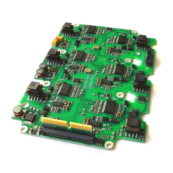
HybridKIT Evaluation Gate Driver Board for 750V EDT2 IGBT
About this document
This application note describes the features as well as limitations of the evaluation gate driver board
EVAL-6ED100HPDRIVE-AS for HybridPACK™ Drive modules with 750V EDT2 IGBTs. A comprehensive
quickstart guide with main interfaces and function description is given. The evaluation gate driver board is
equal to the gate driver boards on the HYBRIDKIT DRIVE Inverter evaluation kits and is an open design for lab
testing purposes.
For evaluation of HybridPACK™ Drive modules with 1200V IGBT4 chipset please see [4].
Author: Tomas Reiter (IFAG ATV HP EDT MD).
Scope and purpose
The evaluation gate driver board was designed to support customers during their first steps in designing
applications with the HybridPACK™ Drive and EICEDriver Sense/Boost. An evaluation board is not intended to
be an optimal design for every specific requirement. But it gives a good starting point and useful design hints
for a serial development. Furthermore, practical experience from the power module switching characteristic as
well as the gate driver features can be obtained in the lab at a minimum effort by using such evaluation tools.
Before getting started it is mandatory to read and understand the safety warnings (section 1.1) and the features
and limitations (chapter 3).
Intended audience
Experienced engineers designing gate drive boards for HybridPACK™ Drive.
Table of Contents
1
Introduction .................................................................................................................. 2
1.1
Safety Warning for Evaluation Kit ........................................................................................................... 2
2
How to order Gate Driver Boards (EVAL-6ED100HPDrive-AS) .............................................. 3
3
Feature and Limitations Overview ................................................................................... 4
3.1
Block Diagram & Key Features ................................................................................................................ 4
3.2
3.3
Recommended Operating Conditions .................................................................................................... 5
3.4
Limitations of the Evaluation Kit ............................................................................................................ 5
3.5
Key Components List .............................................................................................................................. 6
4
Quickstart Guide ............................................................................................................ 7
4.1
Recommended equipment for evaluation ............................................................................................. 7
4.2
Interface and Testpad Description ......................................................................................................... 7
4.2.1
Signal Connector Pinnout & Interface PCB ....................................................................................... 7
4.2.2
Overview of Testpads ......................................................................................................................... 8
4.3
Supply of the Gate Driver Board ............................................................................................................. 9
4.4
Double Pulse Testing in driver DEBUG Mode (w/o SPI communication) ............................................ 10
4.4.1
Enabling DEBUG Mode ..................................................................................................................... 10
4.4.2
Switching the gate driver ................................................................................................................. 11
4.5
Using the gate driver boad with HybridKIT logic board....................................................................... 12
4.6
Digital NTC Measurement R2f converter (SPI required) ...................................................................... 12
5
References and Revision History .................................................................................... 13
Application Note
www.infineon.com
Please read the Important Notice and Warnings at the end of this document
<Revision 1.2>
<2017-11-09>
Advertisement
Table of Contents

Related Manuals for Infineon EVAL-6ED100HPDRIVE-AS


Summary of Contents for Infineon EVAL-6ED100HPDRIVE-AS
-
Page 1: Table Of Contents
This application note describes the features as well as limitations of the evaluation gate driver board EVAL-6ED100HPDRIVE-AS for HybridPACK™ Drive modules with 750V EDT2 IGBTs. A comprehensive quickstart guide with main interfaces and function description is given. The evaluation gate driver board is equal to the gate driver boards on the HYBRIDKIT DRIVE Inverter evaluation kits and is an open design for lab testing purposes. -
Page 2: Introduction
Evaluation Kit and undertakes to indemnify and hold Infineon Technologies harmless from any third party claim in connection with or arising out of the use and/or handling of the Evaluation Kit by the customer. -
Page 3: How To Order Gate Driver Boards (Eval-6Ed100Hpdrive-As)
HybridKIT Evaluation Gate Driver Board for 750V EDT2 IGBT How to order Gate Driver Boards (EVAL-6ED100HPDrive-AS) How to order Gate Driver Boards (EVAL-6ED100HPDrive-AS) The evaluation gate driver board EVAL-6ED100HPDRIVE-AS, compatible for HybridPACK™ Drive 750V EDT2 IGBT modules FSxxxR08A6P2xx, can be ordered via Infineon Sales Partners: ... -
Page 4: Feature And Limitations Overview
Manual for HybridKIT Evaluation Gate Board HybridKIT Evaluation Gate Driver Board for 750V EDT2 IGBT Feature and Limitations Overview Feature and Limitations Overview Block Diagram & Key Features The Figure 2 shows the block diagram with simplified signal and power flow. Figure 2 Simplified block diagram. -
Page 5: Recommended Operating Conditions
It is not a considered product for end customers. The intention of the evaluation gate driver board is to support engineers in their first steps designing with the Infineon EICEDrivers and HybridPACKs. Please see also the section 3.4 in order to understand the limitations. -
Page 6: Key Components List
Table 2 Key components list. Part Number Manufacturer Description / Implementation 1EDI2010AS Infineon Technologies AG Automotive Isolated Gate Driver EICEDriver Sense (1EDI2015AS) (EICEDriver Lite) 1EBN1002AE Infineon Technologies AG... -
Page 7: Quickstart Guide
Signal Connector Pinnout & Interface PCB The evaluation gate driver board is equipped with a Samtec board to board connector. It is compatible to the Infineon Aurix Microcontroller logic board, which is used for all HybridKits. The small interface PCB is designed as 1:1 connector. -
Page 8: Overview Of Testpads
Manual for HybridKIT Evaluation Gate Board HybridKIT Evaluation Gate Driver Board for 750V EDT2 IGBT Quickstart Guide 4.2.2 Overview of Testpads The gate driver board is equipped with several SMD testpads. The signals are written on the PCB close to the corresponding testpad. -
Page 9: Supply Of The Gate Driver Board
Manual for HybridKIT Evaluation Gate Board HybridKIT Evaluation Gate Driver Board for 750V EDT2 IGBT Quickstart Guide Supply of the Gate Driver Board The gate driver board requires a low voltage supply between 8V..18V for the operation. For longer testing times a voltage at about 14V is preferred. -
Page 10: Double Pulse Testing In Driver Debug Mode (W/O Spi Communication)
Manual for HybridKIT Evaluation Gate Board HybridKIT Evaluation Gate Driver Board for 750V EDT2 IGBT Quickstart Guide Double Pulse Testing in driver DEBUG Mode (w/o SPI communication) 4.4.1 Enabling DEBUG Mode The evaluation gate driver board is designed with the new automotive EICEDriver Sense/Boost ICs. These come with a high number of programmable features (via SPI communication). -
Page 11: Switching The Gate Driver
Manual for HybridKIT Evaluation Gate Board HybridKIT Evaluation Gate Driver Board for 750V EDT2 IGBT Quickstart Guide 4.4.2 Switching the gate driver After the DEBUG mode is activated (section 4.4.1) the gate driver is ready to be switched without SPI communication. -
Page 12: Using The Gate Driver Boad With Hybridkit Logic Board
Manual for HybridKIT Evaluation Gate Board HybridKIT Evaluation Gate Driver Board for 750V EDT2 IGBT Quickstart Guide Using the gate driver boad with HybridKIT logic board The evaluation gate driver board is equal to the gate driver board used in the HYBRIDKIT DRIVE inverter evaluation kits. -
Page 13: References And Revision History
References and Revision History References and Revision History The referenced application notes can be found at http://www.infineon.com Infineon Application Note AN-HPD-ASSEMBLY, “Assembly Instructions for the HybridPACK Drive”. Infineon Application Note AN-HPDKIT-QUICKSTART, “HybridKit Drive Quickstart Guide”. Infineon Application Note AN-HPDKIT-ADVANCED-FEATURES, “HybridKit Drive Advanced Features”. - Page 14 Trademarks of Infineon Technologies AG AURIX™, C166™, CanPAK™, CIPOS™, CoolGaN™, CoolMOS™, CoolSET™, CoolSiC™, CORECONTROL™, CROSSAVE™, DAVE™, DI-POL™, DrBlade™, EasyPIM™, EconoBRIDGE™, EconoDUAL™, EconoPACK™, EconoPIM™, EiceDRIVER™, eupec™, FCOS™, HITFET™, HybridPACK™, Infineon™, ISOFACE™, IsoPACK™, i-Wafer™, MIPAQ™, ModSTACK™, my-d™, NovalithIC™, OmniTune™, OPTIGA™, OptiMOS™, ORIGA™, POWERCODE™, PRIMARION™, PrimePACK™, PrimeSTACK™, PROFET™, PRO-SIL™, RASIC™, REAL3™, ReverSave™, SatRIC™, SIEGET™, SIPMOS™, SmartLEWIS™, SOLID FLASH™, SPOC™, TEMPFET™,...
Need help?
Do you have a question about the EVAL-6ED100HPDRIVE-AS and is the answer not in the manual?
Questions and answers