Table of Contents
Advertisement
Quick Links
EVAL-FFXMR20KM1HDR
Evaluation board description and getting started guide
User guide
UG-2022-14
About this document
The purpose of this board is to enable the evaluation of the FF6MR20KM1H, FF4MR20KM1H and FF3MR20KM1H
CoolSiC™ MOSFET modules. The evaluation board allows users to evaluate the device performance via double-
pulse measurements.
Scope and purpose
The properties of this board are described in the design features' chapter of this document. The remaining
sections provide information to enable designers to copy, modify and qualify the design for production,
according to the customer-specific requirements.
Environmental regulations have been considered in the design of the EVAL-FFXMR20KM1HDR board.
Components qualified for a lead-free, reflow soldering process have been selected. The design has been tested
as described in this document, but not qualified regarding manufacturing and operation over the whole
operating temperature range or lifetime.
Intended audience
This document is intended for engineers who want to document and evaluate the switching performance of
Infineon CoolSiC™ 62 mm 2kV modules.
Evaluation board
This board will be used during design-in, for evaluation and measurement of characteristics, and proof of data
sheet specifications.
Note:
PCB and auxiliary circuits are NOT optimized for final customer design.
User guide
Please read the Important Notice and Warnings at the end of this document
Revision 1.0
www.infineon.com
page 1 of 24
2022-08-07
Advertisement
Table of Contents

Subscribe to Our Youtube Channel
Related Manuals for Infineon EVAL-FFXMR20KM1HDR


Summary of Contents for Infineon EVAL-FFXMR20KM1HDR
-
Page 1: About This Document
Environmental regulations have been considered in the design of the EVAL-FFXMR20KM1HDR board. Components qualified for a lead-free, reflow soldering process have been selected. The design has been tested as described in this document, but not qualified regarding manufacturing and operation over the whole operating temperature range or lifetime. -
Page 2: Important Notice
Boards provided by Infineon Technologies. The design of the Evaluation Boards and Reference Boards has been tested by Infineon Technologies only as described in this document. The design is not qualified in terms of safety requirements, manufacturing and operation over the entire operating temperature range or lifetime. -
Page 3: Safety Precautions
EVAL-FFXMR20KM1HDR Evaluation board description and getting started guide Safety precautions Safety precautions Please note the following warnings regarding the hazards associated with development systems. Table 1 Safety precautions Warning: The DC link potential of this board is up to 1500 VDC. When measuring voltage waveforms by oscilloscope, high voltage differential probes must be used. -
Page 4: Table Of Contents
Prerequisites ............................ 11 2.2.2 2.1.2 EiceDRIVER™ 1ED38x0 DCT software installation process ............. 11 2.2.3 Evaluation of the EVAL-FFXMR20KM1HDR board with another microcontroller ......11 2.2.4 Power-up sequence ......................... 11 Introduction to EiceDRIVER™ 1ED38x0 DCT ..................13 System design ........................15 Schematics ............................ -
Page 5: The Evaluation Board At A Glance
Due to the usage of the EiceDRIVER™ 1ED38x0Mc12M and its flexible parameter setting options via I2C-BUS the EVAL-FFXMR20KM1HDR can be quickly adapted to different applications (like DC/DC-converter, Solar applications, UPS systems, Solid state transformer, Drives and others) without changing the hardware. -
Page 6: Delivery Content
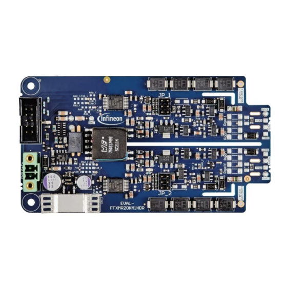
The board appears as shown in Figure 1. For a complete testing of the board some components must be ordered in addition as shown in Figure 2. The Infineon EVAL-1ED38X0DCT microcontroller board ideally be used in order to be able to configure all the parameters in an easy and fast manner. On the power side, any 62mm 2kV half bridge module can be used for evaluation purpose. -
Page 7: Main Features
The evaluation board at a glance Main features The EVAL-FFXMR20KM1HDR is an evaluation board for the EiceDRIVER™ 1ED38x0Mc12M gate drivers ICs to be used together with our 62 mm 2 kV half-bridge module with CoolSiC™ MOSFET. The board is designed for easy measurement and configuration of the gate driver and module parameters. -
Page 8: Typical Applications
The EVAL-FFXMR20KM1HDR operates with a supply voltage of up to 24 V. It generates an output voltage of up to 18 V at the gate terminals, depending on the load conditions. To switch the device, a pulse width modulation (PWM) for both, the top and the bottom side need to be applied at the connector input. -
Page 9: System And Functional Description
1. Connector for input signals (find the pin assignment in Table 4) 2. Infineon self-oscillating half-bridge driver IC IR2085S 3. Infineon 1ED3890MU12M single-channel 5.7 kV (rms) isolated gate driver IC with I2C configurability 4. Negative gate-source voltage adjustment 5. Booster stage 6. -
Page 10: Description Of The Functional Blocks
′ Equation to calculate Vneg for the negative gate voltage adjustments Figure 6 The EVAL-FFXMR20KM1HDR is equipped with the EiceDRIVER™ Enhanced single-channel isolated gate driver 1ED3890MC12M. The 1ED3890MC12M belongs to the EiceDRIVER™ Enhanced 1ED38xx family (X3 digital family) and has a I C bus for parameter adjustment. -
Page 11: Prerequisites
2.2.3 Evaluation of the EVAL-FFXMR20KM1HDR with another microcontroller While not recommended to new users or for fast evaluation, the EVAL-FFXMR20KM1HDR can be used with any microcontroller capable of communicating over I C and generating PWM signals. For this, it is important to read the documentation, especially the reference manual, of the gate drivers. - Page 12 Landing page after starting the GUI 1ED38x0_DCT.exe Figure 7 Figure 8 shows the landing page that is available once the communication between the computer, the EiceDRIVER™ Eval-1ED38x0DCT and the EVAL-FFXMR20KM1HDR is working. Please click on the quick start button for that. User guide 12 of 24 Revision 1.0...
-
Page 13: Introduction To Eicedriver™ 1Ed38X0 Dct
EiceDRIVER™ 1ED38x0 DCT microcontroller board can be used with the EVAL-FFXMR20KM1HDR. It is recommended that first-time users select the guided mode, as this also provides a detailed explanation of each configurable parameter as shown in Figure 9. - Page 14 EVAL-FFXMR20KM1HDR Evaluation board description and getting started guide System and functional description Example: DESAT 1 voltage threshold level of the guided mode Figure 9 Figure 9 shows the guided mode with more details on how to configure the threshold level of the DESAT 1 function for example.
-
Page 15: System Design
System design System design The EVAL-FFXMR20KM1HDR is a simple driver board for evaluating the switching performance of our 62 mm module including our new 2kV CoolSiC™ Trench MOSFET technology. All functional blocks are designed to show a simple circuit approach to accommodate the best performance of our new SiC devices. - Page 16 EVAL-FFXMR20KM1HDR Evaluation board description and getting started guide System design FFXMR12KM1DR with the top layer highlighted Figure 12 FFXMR12KM1DR with the bottom layer highlighted Figure 13 User guide 16 of 24 Revision 1.0 2023-03-27...
- Page 17 EVAL-FFXMR20KM1HDR Evaluation board description and getting started guide System design FFXMR12KM1DR with the internal layer 1 highlighted Figure 14 FFXMR12KM1DR with the internal layer 2 highlighted Figure 15 User guide 17 of 24 Revision 1.0...
-
Page 18: Bill Of Material
EVAL-FFXMR20KM1HDR Evaluation board description and getting started guide System design Bill of material Please note that the detailed BOM of the EVAL-FFXMR20KM1HDR is available at www.infineon.com. Connector details Table 3 Connector X1 Label Function X1.1... -
Page 19: System Performance
EVAL-FFXMR20KM1HDR Evaluation board description and getting started guide System performance System performance Test setup Figure 16 captures the test setup and voltage measurement techniques for double-pulse testing. The first turn- on pulse of the low-side device (S2) establishes the desired current value (e.g. nominal data sheet current in this case) in the inductive load, and the turn-off pulse makes the current flow in the freewheeling diode (e.g. -
Page 20: Switching Performance
EVAL-FFXMR20KM1HDR Evaluation board description and getting started guide System performance Switching performance This chapter presents some examples of extracted waveforms of the module FF6MR20KM1H, which has been characterized with the help of the evaluation board. -
Page 21: Mosfet Switch-Off Behavior
EVAL-FFXMR20KM1HDR Evaluation board description and getting started guide System performance Turn on waveforms of typical bipolar voltage values with V = -3…+15 V /…+18 V. Figure 18 4.2.2 MOSFET switch-off behavior The turn-off switching with different bipolar voltage levels was observed by changing the R... -
Page 22: References And Appendices
References and appendices References Infineon Technologies AG. AN2013-10 (Rev. 2014): External Booster for Driver IC V 1.6 www.infineon.com Infineon Technologies AG. AN2019-25: CoolSiC™ MOSFET motor drives evaluation board for 7.5 kW - Eval- M5-E1B1245N-SiC www.infineon.com Additional information This is a preliminary version of the user guide before the final release of the board. -
Page 23: Revision History
EVAL-FFXMR20KM1HDR Evaluation board description and getting started guide Revision history Revision history Document Date of release Description of changes version 2023-03-27 Preliminary version User guide 23 of 24 Revision 1.0 2023-03-27... - Page 24 WARNINGS 81726 Munich, Germany Due to technical requirements products may contain dangerous substances. For information on the types in question please contact your nearest Infineon © 2024 Infineon Technologies AG. Technologies office. All Rights Reserved. Except as otherwise explicitly approved by Infineon...
Need help?
Do you have a question about the EVAL-FFXMR20KM1HDR and is the answer not in the manual?
Questions and answers