Table of Contents
Advertisement
Quick Links
EVAL_PMG1_S1_DRP Evaluation Kit user guide
About this document
Scope and purpose
The EVAL_PMG1_S1_DRP kit is an evaluation kit for USB Power Delivery dual role port (DRP) applications using
the EZ-PD™ PMG1-S1 (Power Delivery Microcontroller Gen1) MCU. EZ-PD™ PMG1 is a family of high-voltage
Power Delivery microcontrollers. These chips include the CPU core, Power Delivery controller, and configurable
integrated analog and digital peripherals. The EZ-PD™ PMG1 MCU is targeted for any embedded system that
powers from a high-voltage USB-C port and needs a microcontroller to control the actions and features of a
product.
Intended audience
This document is intended for designers using the EVAL_PMG1_S1_DRP Evaluation Kit (EVK).
Reference Board/Kit
Product(s) embedded on a PCB, with focus on specific applications and defined use cases that can include
software. PCB and auxiliary circuits are optimized for the requirements of the target application.
Note:
Boards do not necessarily meet safety, EMI, quality standards (for example UL, CE) requirements.
User guide
Please read the sections "Important notice" and "Warnings" at the end of this document
002-38792 Rev. *B
www.infineon.com
2024-06-19
Advertisement
Table of Contents

Subscribe to Our Youtube Channel
Related Manuals for Infineon EVAL PMG1 S1 DRP


Summary of Contents for Infineon EVAL PMG1 S1 DRP
-
Page 1: About This Document
PCB and auxiliary circuits are optimized for the requirements of the target application. Note: Boards do not necessarily meet safety, EMI, quality standards (for example UL, CE) requirements. User guide Please read the sections “Important notice” and “Warnings” at the end of this document 002-38792 Rev. *B www.infineon.com 2024-06-19... -
Page 2: Important Notice
Boards provided by Infineon Technologies. The design of the Evaluation Boards and Reference Boards has been tested by Infineon Technologies only as described in this document. The design is not qualified in terms of safety requirements, manufacturing and operation over the entire operating temperature range or lifetime. -
Page 3: Safety Precautions
EVAL_PMG1_S1_DRP Evaluation Kit user guide Safety precautions Safety precautions Note: Please note the following warnings regarding the hazards associated with development systems. Table 1 Safety precautions Caution: The EVAL_PMG1_S1_DRP kit is intended for use as an evaluation platform for hardware or software in a laboratory environment. The board is an open-system design, which does not include a shielded enclosure. -
Page 4: Table Of Contents
EVAL_PMG1_S1_DRP Evaluation Kit user guide Table of contents Table of contents About this document ........................1 Important notice ..........................2 Safety precautions .......................... 3 Table of contents ..........................4 Introduction .......................... 5 Key features ............................. 5 Kit contents ............................. 5 1.2.1 Hardware not included with the kit .................... -
Page 5: Introduction
EVAL_PMG1_S1_DRP Evaluation Kit user guide Introduction Introduction The EVAL_PMG1_S1_DRP EVK is based on the EZ-PD™ PMG1-S1 MCU, which is part of the EZ-PD™ PMG1 USB-C Power Delivery (PD) MCU portfolio. This EVK is intended to be an evaluation vehicle for customers who want to use EZ-PD™... -
Page 6: Getting Started
EVAL_PMG1_S1_DRP Evaluation Kit user guide Introduction Getting started For instruction to run a quick demonstration and observe the kit functionality, see the Kit operation section. Download the documents and the hardware design files for EVK from the kit webpage. The documents include a quick start guide, kit guide (this document), and release notes. -
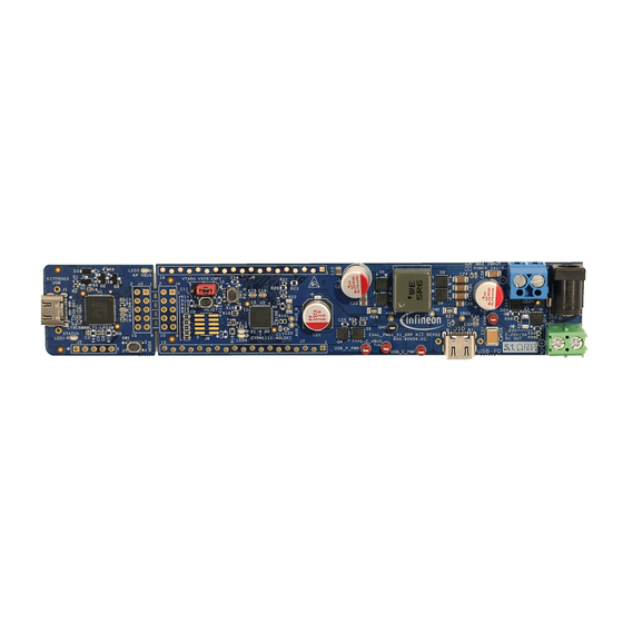
Page 7: Board Details
EVAL_PMG1_S1_DRP Evaluation Kit user guide Board details Board details Figure 1 Figure 2 show the front and back views of the board with critical components highlighted for the EVAL_PMG1_S1_DRP EVK, which are essential for kit functionality demonstration. LED2 LED4 LED3 LED1 Q4 Q5 Front view of the board... - Page 8 EVAL_PMG1_S1_DRP Evaluation Kit user guide Board details EVK components Table 3 REFDES Component Description EZ-PD™ PMG1-S1 MCU EZ-PD™ PMG1-S1 single-port USB Type-C Power Delivery (PD) high- voltage MCU (CYPM1111-40LQXI) Q4, Q5 Provider FETs MOSFET P-CH 30 V 40A TSDSON-8 (BSZ180P03NS3GATMA1) Q10, Consumer FETs MOSFET P-CH 30 V 40A TSDSON-8...
- Page 9 EVAL_PMG1_S1_DRP Evaluation Kit user guide Board details Connectors and terminal blocks Table 6 REFDES Connector name Description KitProg3 USB Type-C connector to connect the KitProg3 with a PC for EVK programming and debugging KitProg3 debug header 10-pin header for connections between KitProg3 and KitProg3 side EZ-PD™...
-
Page 10: Eval_Pmg1_S1_Drp Kit System Design
3.3 V Barrel jack DC input J11 / J12 Power conversion and switch Infineon part Loaded parts No loaded parts EVAL PMG1-S1 DRP kit block diagram Figure 3 The EZ-PD™ PMG1-S1 MCU includes an Arm® Cortex® M0-MCU with the following features: 128 KB flash •... -
Page 11: System Power Supply Design
EVAL_PMG1_S1_DRP Evaluation Kit user guide EVAL_PMG1_S1_DRP kit system design System power supply design The EVK consists of two step-down regulators to generate the 5 V and 3.3 V outputs to provide for VCONN, board peripherals, and EZ-PD™ PMG1-S1 MCU system power. The 5 V DC-DC converter generates 5 V from the DC input power supply when the EVK is in source mode. -
Page 12: Power Selection Jumper
EVAL_PMG1_S1_DRP Evaluation Kit user guide EVAL_PMG1_S1_DRP kit system design 3.1.1 Power selection jumper The EZ-PD™ PMG1-S1 MCU on the EVK operates with two possible external supply voltages, VBUS or VSYS. The VDDIO supply powers the device I/Os. VDDD generates 3.3 V from an internal regulator, and this can be shorted to VDDIO. -
Page 13: Provider And Consumer Switch
EVAL_PMG1_S1_DRP Evaluation Kit user guide EVAL_PMG1_S1_DRP kit system design Provider and consumer switch The EZ-PD™ PMG1-S1 device consists of two I/Os with integrated PFET gate drivers: VBUS_P_CTRL and VBUS_C_CTRL. These drivers control the VBUS provider (sourcing of power) and consumer (sinking of power) path connecting the Type-C port to the power source and consumer. - Page 14 EVAL_PMG1_S1_DRP Evaluation Kit user guide EVAL_PMG1_S1_DRP kit system design VBUS provider and consumer path Figure 7 User guide 002-38792 Rev. *B 2024-06-19...
-
Page 15: I/O Headers
EVAL_PMG1_S1_DRP Evaluation Kit user guide EVAL_PMG1_S1_DRP kit system design I/O headers The EVAL_PMG1_S1_DRP kit has two I/O headers: J6 and J7, placed on either side of the board. These headers are standard breadboard compatible. EVK I/O headers Figure 8 Table 7 I/O header pinout at J6 pin EVK pin name EZ-PD™... - Page 16 EVAL_PMG1_S1_DRP Evaluation Kit user guide EVAL_PMG1_S1_DRP kit system design EVK pin name EZ-PD™ Primary function Secondary Connection pin J6 PMG1-S1 function details MCU pin SW_IN User switch output. P2.0 (GPIO) Connected to SW2 and P2.0 SW2 is input to the pin through a EZ-PD™...
-
Page 17: Programming And Debugging
EVAL_PMG1_S1_DRP Evaluation Kit user guide EVAL_PMG1_S1_DRP kit system design EVK pin name EZ-PD™ Primary function Secondary Connection pin J7 PMG1-S1 function details MCU pin P5_1/I2C_SCL Connected to SCB0 I2C SCL P5.1 (GPIO) KitProg3 for USB- to-I2C bridge SCB0 I2C SDA P5.0 (GPIO) Connected to P5_0/I2C_SDA... - Page 18 SWD data UART_TX UART TX The EVK also has a 10-pin SWD/JTAG header (J8) for programming and debugging. The header is pin- compatible with all standard 10-pin SWD/JTAG interfaces and supports the Infineon MiniProg4 program and debug kit. RESET SWDCLK...
-
Page 19: User Led And Switch
EVAL_PMG1_S1_DRP Evaluation Kit user guide EVAL_PMG1_S1_DRP kit system design User LED and switch The EVK has one user LED and user switch connected to the EZ-PD™ PMG1-S1 MCU GPIOs. The user LED (green) is connected to the P2.1 and its functionality can be configured via the firmware. The GPIO needs to be driven LOW to turn on the user LED (LED3). -
Page 20: Kit Operation
EVAL_PMG1_S1_DRP Evaluation Kit user guide Kit operation Kit operation This section explains the operation, programming, and debugging modes of the kit. It also describes the procedure for programming and debugging the application firmware on the kit. The EVK is designed to work as a USB PD DRP. By default, this kit is loaded with the firmware associated with the USB PD DRP code example, supported in ModusToolbox™. -
Page 21: Usb Pd Source Operation
EVAL_PMG1_S1_DRP Evaluation Kit user guide Kit operation USB PD source operation The EVK is designed to work as a USB PD DRP and the firmware associated with the USB PD DRP code example supported in the ModusToolbox™ software is downloaded in the factory on the kit. The EVK supports up to a maximum contract of 20 V and 5A (100 W) in the source mode. -
Page 22: Application Development On Evk Using Modustoolbox™ And Modustoolbox™ Programmer
EVAL_PMG1_S1_DRP Evaluation Kit user guide Application development on EVK using ModusToolbox™ and ModusToolbox™ programmer Application development on EVK using ModusToolbox™ and ModusToolbox™ programmer The EZ-PD™ PMG1 MCU-based projects are developed using the ModusToolbox™ software development tool. ModusToolbox™ software is a set of multiplatform development tools and a comprehensive suite of GitHub- hosted firmware libraries. - Page 23 EVAL_PMG1_S1_DRP Evaluation Kit user guide Application development on EVK using ModusToolbox™ and ModusToolbox™ programmer Eclipse IDE for ModusToolbox™ software Figure 16 6. On the Quick Panel, click <Application name> Program (KitProg3_MiniProg4) from the Launches section. Quick panel and programming options Figure 17 7.
-
Page 24: Using Modustoolbox™ Programmer (Mtbp)
EVAL_PMG1_S1_DRP Evaluation Kit user guide Application development on EVK using ModusToolbox™ and ModusToolbox™ programmer 5.1.2 Using ModusToolbox™ programmer (MTBP) ModusToolbox™ programmer (MTBP) is a standalone, cross-platform, and flash programmer tool. Mtb- programmer provides a GUI to program, erase, verify, and read the flash of the target MCU. MTBP supports the HEX, SREC, ELF, and BIN programming file formats. -
Page 25: Debug Mode Using Kitprog3 Interface Using Modustoolbox
EVAL_PMG1_S1_DRP Evaluation Kit user guide Application development on EVK using ModusToolbox™ and ModusToolbox™ programmer 7. Click Program to initiate the firmware update. The message “Device programmed successfully” appears on the bottom left after the programming is complete as shown in Figure Programming through ModusToolbox™... -
Page 26: Programming And Debugging Using J-Link Debug Probes
EVAL_PMG1_S1_DRP Evaluation Kit user guide Application development on EVK using ModusToolbox™ and ModusToolbox™ programmer 4. Connect the kit to the host PC through the programming KitProg3 USB Type-C port. Ensure that the LED1 and LED2 glow amber. 5. On the Quick Panel, click <Application name> Debug (KitProg3_MiniProg4) from the Launches section. 6. -
Page 27: Troubleshooting
EVAL_PMG1_S1_DRP Evaluation Kit user guide Troubleshooting Troubleshooting Table 11 lists the common problems and troubleshooting methods that may be encountered during operation in the Kit operation section. Common troubleshooting methods Table 11 S. No. Issue Possible cause Possible solution(s) The EVK USB PD Type-C The power selection jumper Set the power selection jumper to port does not enter PD... -
Page 28: Appendices
EVAL_PMG1_S1_DRP Evaluation Kit user guide Appendices Appendices Appendix A 7.1.1 KitProg3 An onboard PSoC™ 5LP MCU (CY8C5868LTI-LP039)-based KitProg3 module is used to program and debug the EZ-PD™ PMG1 MCU. PSoC™ 5LP MCU-based KitProg3 Figure 24 The PSoC™ 5LP MCU device interfaces with a PC through a Type-C USB connector (J1) and functions as a bridge between the PC and EZ-PD™... -
Page 29: Mode Switch
EVAL_PMG1_S1_DRP Evaluation Kit user guide Appendices 7.1.1.1 Mode switch The KitProg3 mode switch in the EZ-PD™ PMG1 MCU family kit enables the KitProg3 module to enter the bootloader mode. The bootloader mode is required to update the KitProg3 firmware on the PSoC™ 5LP MCU when the existing firmware corrupts, or a newer version is available. -
Page 30: Eval_Pmg1_S1_Drp Schematics
EVAL_PMG1_S1_DRP Evaluation Kit user guide Appendices Appendix B 7.2.1 EVAL_PMG1_S1_DRP schematics KitProg3 schematics Figure 27 User guide 002-38792 Rev. *B 2024-06-19... - Page 31 EVAL_PMG1_S1_DRP Evaluation Kit user guide Appendices DC input power & system regulator schematics Figure 28 User guide 002-38792 Rev. *B 2024-06-19...
- Page 32 EVAL_PMG1_S1_DRP Evaluation Kit user guide Appendices PMG1 S1 MCU schematics Figure 29 User guide 002-38792 Rev. *B 2024-06-19...
- Page 33 EVAL_PMG1_S1_DRP Evaluation Kit user guide Appendices USB PD source regulator schematics Figure 30 User guide 002-38792 Rev. *B 2024-06-19...
- Page 34 EVAL_PMG1_S1_DRP Evaluation Kit user guide Appendices USB PD provider and consumer switch schematics Figure 31 User guide 002-38792 Rev. *B 2024-06-19...
-
Page 35: Glossary
EVAL_PMG1_S1_DRP Evaluation Kit user guide Glossary Glossary adaptive fast charging Battery Charging Downstream Facing Port Do Not Populate Dual Role Power EMCA Electronically Marked Cable Assembly electrostatic discharge Evaluation Kit Field-Effect Transistor GPIO general-purpose input/ output integrated circuit light-emitting diode not applicable overvoltage protection power adapter... - Page 36 EVAL_PMG1_S1_DRP Evaluation Kit user guide Glossary PSoC™ programmable system on chip system on chip Upstream Facing Port Universal Serial Bus USB PD Universal Serial Bus Power Delivery undervoltage protection User guide 002-38792 Rev. *B 2024-06-19...
-
Page 37: Revision History
EVAL_PMG1_S1_DRP Evaluation Kit user guide Revision history Revision history Document Date Description of changes revision 2023-08-11 Initial release 2024-03-12 Updated kit images with Rev02 of kit. Added warnings in section 4. Added schematics in EVAL_PMG1_S1_DRP schematics. 2024-06-19 Updated kit images with Rev03 of kit. Updated schematics screenshots with Rev03 of kit. -
Page 38: Disclaimer
Published by Infineon Technologies office. Except as otherwise explicitly approved by Infineon Technologies AG Infineon Technologies in a written document 81726 Munich, Germany signed by authorized representatives of Infineon Technologies, Infineon Technologies’ products may not be used in any applications where a ©...
Need help?
Do you have a question about the EVAL PMG1 S1 DRP and is the answer not in the manual?
Questions and answers