Chapters
Table of Contents

Related Manuals for Vicon EXTRA 632 FR


Summary of Contents for Vicon EXTRA 632 FR
- Page 1 EXTR 632 FR Operator's Manual Translated from the original instruction manual Date of publication 01/2012 Date printed 01/2012 Language Valid as from serial No.: KT 421.939 Reference No: 91015201EN Index 2012-01...
- Page 2 Identification of machine For your dealer to help you as quickly as possible, he needs to have certain information about your machine. Please enter this information here. Extr 632FR Description Extr 632FR: 3.2 m Working width Extr 632 FR: 1227 kg Weight Machine number Accessories...
-
Page 3: Table Of Contents
Contents Contents Contents ............4 Optional equipment ........119 Instruction manual target group High skids The meaning of the symbols Chain for locking the front lift device Quick release of knives Safety ..............5 Straw divider For your own safety A-frame Who can operate the machine? PTO shaft Connecting Lighting kit... -
Page 4: Contents
Contents Contents Instruction man- This instruction manual is intended for trained farmers and others who are qualified to work in agriculture and who are familiar with ual target group assembling equipment. For your own safety Read this instruction manual thoroughly before use and mounting. By doing this you have optimal working conditions and you can work in safety. -
Page 5: For Your Own Safety
Safety Safety For your own This chapter includes general safety instructions. Furthermore, each chapter in the instruction manual includes specific safety instructions safety that are not described here. The safety instructions must be complied with • In terms of your own safety. •... - Page 6 Safety Safety symbols On the machine you will find labels relating to your safety. These labels must not be removed. If the labels become illegible or fall off, you can order some new labels and affix them to the relevant areas. Transport...
- Page 7 Safety The meaning of the Stop the tractor before working on the machine symbols Be attentive! The tractor engine must ALWAYS be stopped and the ignition key removed before carrying out repairs, cleaning, lubricating or maintaining the machine. Read and observe the instruction manual Be attentive! Read and understand the instruction manual before the machine is put into service.
- Page 8 Safety Risk of trapping fingers or hands Be careful as there is a risk that hands or fingers may be trapped when the machine is raised. Risk of trapping fingers or hands Be careful as there is a risk that hands or fingers may be trapped when the machine is lowered.
-
Page 9: Who Can Operate The Machine
Safety Who can operate Operators of this machine should only be educated farmers and persons who in other ways are qualified to perform agricultural work the machine? and who have knowledge on installing the equipment. Untrained or unauthorised persons must not use this machine. Connecting Correct attachment of the machine The machine must be correctly attached, in accordance with the... -
Page 10: Load Capacity
Safety Only connect the hydraulics when the system is depressurised You should only connect the hydraulic hoses to the tractor's hydraulics when the hydraulic system on both tractor and machine is depressurised. There is a risk that the machine will move unintentionally. Unintentional movement of the machine may result in serious injuries. -
Page 11: Transport On Public Roads
Safety Transport on Control that the machine meets the Road Traffic Act's requirements concerning its condition public roads When driving on public roads, the machine must live up to the Road Traffic Act's current requirements. 95-012 fr This ensures traffic safety both for you and other road users. Not meeting the requirements can result in accidents. -
Page 12: Use
Safety The operator should be instructed carefully before the machine is put into use Only use the machine when the operator has been given thorough instructions. Thorough machine instruction allows safe usage. 95-002-1 fr Insufficient instructions can result in wrong usage of the machine and accidents. - Page 13 Safety Check the surrounding area before taking machine into use Before driving and using the machine the surrounding area should be checked. This prevents persons and animals in the vicinity from being harmed. If the surrounding area is not checked, it may result in serious injuries to persons or animals.
-
Page 14: Disconnection
Safety Disconnection Heightened risk of personal injury when disengaging There is an increased risk of personal injury when disengaging the machine from the tractor. Adherence to the above instructions will ensure your own safety and that of others. Failure to follow the above instructions may result in serious injuries. Therefore, when disconnecting: •... -
Page 15: Maintenance
Safety Maintenance Comply with the service and maintenance intervals given in the instructions Comply with the intervals for service and maintenance as given in the instructions. By complying with the maintenance intervals you assure that the machine will operate without malfunctions and give maximum protection to the surroundings. - Page 16 Safety Be careful when cleaning with high pressure cleaner Only clean bearings, hydraulic hoses, plastic components, electrical control boxes and electrical equipment with low water pressure. By cleaning with low water pressure you will protect sensitive equipment on the machine. Cleaning with high water pressure could damage vital parts of the machine.
-
Page 17: Further Safety Instructions
Safety Further safety in- Follow the instructions when working on the machine The machine safety instructions must always be complied with. structions It will protect you and others from personal injury. Failure to follow the safety instructions may result in serious injuries. Apart from the safety instructions the following should be complied with: 95-005 fr... -
Page 18: About The Machine
About the machine This chapter includes general information about your machine. About the machine Furthermore, following information are included: • The machine application area. • The machine characteristics. • View of the machine. • Technical data. The field of appli- 632 FR is a swather intended to lay common grass and cereal crops in swathes. -
Page 19: Machine Characteristics
About the machine Machine Description of the machine 632 FR is a swather which operates at the front of the tractor and is characteristics coupled to the lift arms on the tractor's front lift device. The machine's cutting unit is hydraulically connected to the main frame of the machine and can be raised and lowered using the tractor's hydraulic system. -
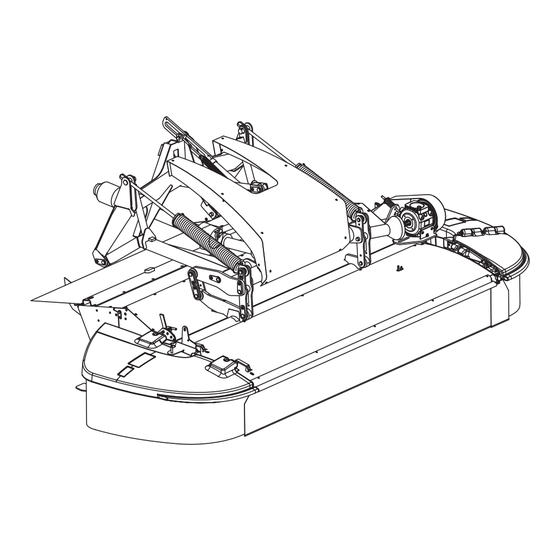
Page 20: Synopsis
About the machine Synopsis Suspension Hydraulic cylinder Springs Springs PTO shaft Guard Transmission Cutterbar... -
Page 21: Technical Data
About the machine Technical data Machine dimensions Dimension Unit 632 FR 2000 1450 1400 3200 2980 1700 4215... - Page 22 About the machine Machine specification Unit 3632 FR Net weight 1267 P.T.O. Power take off 1000 Power requirement kW/HK 60 / 80 Number of discs Number of knives RPM, cutting discs 3000 RPM, rollers Hydraulic flow (max) L/min Hydraulic pressure (max) Working width Speed during operation 8 - 16...
-
Page 23: Tractor Requirements
About the machine Tractor Tractor weight and size The tractor must have a proper weight. Local regulations governing requirements this relationship must be observed. The correct ratio between tractor and machine secure proper braking functions and manoeuvrability. An incorrect ratio between tractor and machine can be dangerous. Front lift device The tractor must be equipped with a front lift device designed for a three-point hitch. -
Page 24: Preparation
Preparation Preparation Preparing the For transporting the user the machine is divided into main components. The machine is assembled according to the specific machine assembly instructions delivered with each machine. The following chapter is for initial assembling, reducing the length of the P.T.O. - Page 25 Preparation Changing to an anti- clockwise direction of rotation The transmission's direction of rotation can be changed in the following way: Guard > Use a suitable tool to remove the guard. Bolt > Remove the support bolts. > Remove the guard. Guard >...
- Page 26 Preparation > Remove the transmission from the machine and place it in the position shown. Air release plug > Remove the air release plug and the oilplug and switch them over. Oilplug...
- Page 27 Preparation > Remove the guard, move it to the opposite output shaft and fit it. Guard > Fit the transmission onto the bracket. Bolt NB Take particular care when engaging the transmission's splined shaft on the machine.
- Page 28 Preparation > Fit the guard. Guard Bolt > Fit the supports. > Fit the guard. Guard...
-
Page 29: Assembly - Attachment
Assembly - attachment Coupling a tractor and a machine together Assembly - attachment There is an increased risk of personal injury when coupling the machine and the tractor. Attention to the safety instructions assures your and others personal safety. Failure to follow the safety instructions may result in serious injuries. Therefore, when connecting the machine and the tractor you should: •... -
Page 30: Attachment Of The Tractor
Assembly - attachment Attachment of the Attaching the machine When attaching the machine there is an increased risk of personal tractor injury. Attention to the safety instructions assures your and others personal safety. Failure to follow the safety instructions may result in serious injuries. Only connect the hydraulics when the system is depressurised You should only connect the hydraulic hoses to the tractor's hydraulics when the hydraulic system on both tractor and machine is... - Page 31 Assembly - attachment Attaching the machine Initial fitting of the machine > Both of the support legs on the machine must be fully lowered. Support leg Lock catch > Fit the A-frame on the tractor's front lift device and drive forwards to the machine.
- Page 32 Assembly - attachment > Raise the machine to the height shown of 700 mm. 700 mm > The chains* shown are tightened so the position is locked. * Extra equipment »Optional equipment« page 119 Chain Support leg > Release the support legs on both sides of the hitch as shown.
- Page 33 Assembly - attachment > Adjust the top link on the front lift device so that the A-frame on the Top link tractor's front lift device is vertical. A-frame...
- Page 34 Assembly - attachment Hydraulic For tractors fitted with a front lift device and which have a hydraulic outlet at the front of the tractor, the machine can be connected to the hydraulic system in the following way: > Connect the tractor hydraulic system as shown. •...
- Page 35 Assembly - attachment For tractors not fitted with a front lift device and which do not have a hydraulic outlet at the front of the tractor, the machine, plus a T-piece retrofitted front lift device, can be connected to the hydraulic system in Hydraulic outlet the following way: >...
- Page 36 Assembly - attachment Standard setting of the suspension > Raise the machine using the machine's hydraulic cylinder. Hydraulic cylinder > Tighten the springs to the dimension shown. 100 - 200 mm > Lower the machine back down to the ground using the machine's hydraulic cylinder.
- Page 37 Assembly - attachment The suspension on the machine's cutting unit should be adjusted so that the downward pressure on the machine's cutting unit is about 40- 60 kg. The cutting unit's suspension can be adjusted as follows: > Use a suitable tool to screw the bolt indicated. •...
- Page 38 Assembly - attachment PTO shaft > Fit the PTO shaft. Min. 200 mm > Check that the PTO shaft's two halves overlap one another by a minimum of 200 mm when the shaft is fitted between the tractor and the machine. >...
-
Page 39: Hydraulic
Assembly - attachment Hydraulic Safety Only connect the hydraulics when the system is depressurised You should only connect the hydraulic hoses to the tractor's hydraulics when the hydraulic system on both tractor and machine is depressurised. There is a risk that the machine will move unintentionally. Unintentional movement of the machine may result in serious injuries. -
Page 40: Connection
Assembly - attachment Connection Hydraulic connection The tractor must be fitted with a single-acting hydraulic outlet for the tractor's front lift device. Hydraulic outlet Control valves The function of the control valves is as follows: Function Valve Raising/lowering the cutting unit single-acting First start-up of The initial test drive of the machine is important... - Page 41 Assembly - attachment Friction clutch Bleeding When first started and/or after a long period without The friction clutch is bled in the following way: > Open the guards around the machine's cutterbar. > Block the cutter bar by placing a wooden block between the two cutting discs.
- Page 42 Assembly - attachment > Disconnect the PTO outlet and stop the tractor. > Remove the friction clutch from the machine. > Unscrew all the screws shown on the friction clutch. > Mount and fasten the friction clutch on the machine. >...
- Page 43 Assembly - attachment Machine in transport Check the surrounding area before taking machine into use position Before driving and using the machine the surrounding area should be checked. This prevents persons and animals in the vicinity from being harmed. If the surrounding area is not checked, it may result in serious injuries to persons or animals.
- Page 44 Assembly - attachment Right-hand side > Tilt the whole guard up as shown. > Fit the linchpin as shown. Left-hand side > Remove the linchpin [1]. > Swivel the guard round as shown [2-3].
- Page 45 Assembly - attachment > Fit the linchpin as shown.
-
Page 46: Transport On Public Roads
Transport on public roads Transport on public roads Safety Read the safety instructions carefully before driving on public road Before driving on public road, you must read the safety instructions carefully. This assures that you avoid dangerous situations and accidents. Lack of information can lead to an accident. -
Page 47: Operation
Operation Operation Safety Read the safety instructions before using the machine Before using the machine, the operator should read the safety instructions carefully. »Safety« page 5 Attention to the safety instructions assures your and others personal safety. Failure to follow the instructions may result in serious injuries. Work on the machine should only be carried out by persons who have been thoroughly instructed The machine should only be operated when the operator has been... -
Page 48: Operation
Operation Operation Safety The operator should be instructed carefully before the machine is put into use Only use the machine when the operator has been given thorough instructions. Thorough machine instruction allows safe usage. Insufficient instructions can result in wrong usage of the machine and accidents. - Page 49 Operation Setting Rollers Rotational speed of the rollers is 900 rpm. Roller pressure The pressure of the rollers on the crop depends on the type and nature of the crop: • When cutting grassy crops, the roller pressure should be increased.
- Page 50 Operation Changing the roller pressure NB The setting for the springs must be exactly the same on both sides of Counter nut the machine. The roller pressure is adjusted in the following way: Left-hand side: > Use the appropriate tools to loosen the counter nut shown, which is located close to the springs.
- Page 51 Operation NB The setting for the springs must be exactly the same on both sides of the machine. The roller pressure is adjusted in the following way: Counter nut Right-hand side: > Use the appropriate tools to loosen the counter nut shown, which is located close to the springs.
- Page 52 Operation Distance between rollers Reducing the distance between rollers The distance between the rollers is reduced in the following way: > Loosen the counter nuts shown. > Reduce the distance between the rollers by screwing the nuts shown.
- Page 53 Operation ! The recommended distance between the rollers is 3 mm. 3 mm The distance between rollers is checked in the following way: ! It is recommended that the check be carried out by 2 operatives. > Place a 3 mm spacer in between the rollers, approximately 50 mm from the outermost end of the roller on both the left and right-hand sides.
- Page 54 Operation Increasing the distance between rollers The distance between the rollers is increased in the following way: > Loosen the counter nuts shown. > Increase the distance between the rollers by screwing the nuts shown.
- Page 55 Operation ! The recommended distance between the rollers is 3 mm. 3 mm The distance between rollers is checked in the following way: ! It is recommended that the check be carried out by 2 operatives. > Place a 3 mm spacer in between the rollers, approximately 50 mm from the outermost end of the roller on both the left and right-hand sides.
- Page 56 Operation Deflector plates The machine is fitted with 2 deflector plates: When the deflector plates are used, the crop is collected into a compact swath. The deflector plates can also be removed from the machine, so the crop is spread out across the whole breadth of the machine. ! The cutting swath should be as wide and even as possible.
- Page 57 Operation Pay attention to the deflector plates On tractors with large front wheels and short lift arms on the front lift, users must be particularly aware of the danger of the wheel coming into contact with the deflector plates when the front wheel is turning, for example when turning at the headland.
- Page 58 Operation Suspension The springs contain a very large amount of stored energy Always proceed with the utmost care and consideration when working with the springs. The springs are loaded with very large amounts of energy which can be released very suddenly. Failure to take due care may result in serious injuries or death.
- Page 59 Operation Working in the field Check the surrounding area before taking machine into use Before driving and using the machine the surrounding area should be checked. This prevents persons and animals in the vicinity from being harmed. If the surrounding area is not checked, it may result in serious injuries to persons or animals.
- Page 60 Operation Left-hand side > Remove the linchpin. > Swivel the guard down as shown [1-2]. > Fit the linchpin [3].
- Page 61 Operation > Set the lift arms on the tractor's front lift device so that the arm shown is 700 mm above the ground. 700 mm > The chains* shown are tightened so the position is locked. * Extra equipment »Optional equipment« page 119 >...
- Page 62 Operation Adjusting the stubble height Top link The stubble height is adjusted as follows: • Reducing the length of the top link increases the stubble height. • Extending the top link reduces the stubble height. Machine start-up > Carefully connect the tractor's PTO outlet. >...
- Page 63 Operation Turning at headlands Turning at the field headland is performed in the following way: > Activate and hold the handle for the tractor's hydraulic outlet. • Raise the cutting unit. > Release the handle for the tractor's hydraulic outlet. >...
-
Page 64: Before Cleaning
Cleaning Cleaning Before cleaning Higher risk when cleaning the equipment When cleaning, there is a higher risk of personal injury. Attention when carrying out cleaning work protects your own and others safety. Failure to follow the safety instructions may result in serious injuries. Therefore, do the following before cleaning: •... -
Page 65: Cleaning
Cleaning Cleaning Use the proper cleaning agents Use only PH neutral cleaning agents when cleaning the machine. PH neutral cleaning agents give your machine a maximum protection. Cleaning agents with either high or low PH value can be corrosive on plastic, rubber and painted surfaces. -
Page 66: Parking And Storage
Parking and Storage Parking and Storage Before storage When the season has come to an end the machine should be prepared for storage: > Check and tighten all bolts. »Torque moment« page 128 > Repair all damaged components. > Replace all defect components. >... - Page 67 Parking and Storage Hydraulic Only disconnect hydraulics when system is without pressure The hydraulic hoses should only be disconnected from the tractor hydraulics when the hydraulic system on both tractor and machine is depressurised. There is a risk that the machine will move unintentionally. Unintentional movement of the machine may result in serious injuries.
- Page 68 Parking and Storage > Place the support legs in the park position on both sides of the hitch as shown. Support leg > Activate the tractor's front lift device and raise the machine to its maximum height. Front lift device...
- Page 69 Parking and Storage > Check that the chains for the tractor's front lift device are slack. > Close the mechanical safety valve for the machine's hydraulic cylinder. > Remove the chains on the tractor's front lift device. > Place the machine on a stable surface. >...
-
Page 70: Storage
Parking and Storage Storage When the season is over, the machine should be readied for winter storage: Carry out the following: • Clean the machine thoroughly. »Cleaning« page 64 • Change the oil in the transmission cases. »Changing the oil« page 105 ... -
Page 71: Maintenance
Maintenance Maintenance For your own Comply with the service and maintenance intervals given in the instructions safety Comply with the intervals for service and maintenance as given in the instructions. By complying with the maintenance intervals you assure that the machine will operate without malfunctions and give maximum protection to the surroundings. -
Page 72: General Instructions
Maintenance General These instructions concern general maintenance work. Specific maintenance work procedures for each machine will be described instructions later. When performing all maintenance work the machine must be secured in the transport position. If the working position is necessary for performing maintenance work, you will find appropriate instructions concerning this work. - Page 73 Maintenance Maintenance inter- vals • • Hydraulic hoses every 4 years • • Universal joint - cutterbar • Cutting disc after 1 hour of use • • Cutting disc • Cutting disc after 1 hour of use • • Knives •...
- Page 74 Maintenance • • Rollers • • • • • • • PTO shaft • • Bearing for the rollers • • spindle for the springs • • Movable mechanical connections...
-
Page 75: Pto Shaft Check
Maintenance Safety in connection with maintenance work on the machine When working on the machine the tractor must be stopped and secured. This prevents the PTO shaft from suddenly starting to rotate. If the tractor and the PTO shaft have not been connected following the instructions, serious accidents causing damage to limbs can occur. -
Page 76: Lubrication
Maintenance Lubrication Every day PTO shaft > Find the hole in the band and turn the PTO shaft until the grease nipple is visible. 58.237.000 > Press the nozzle on the grease gun over the grease nipple. > Pump 1, max. 2 times with the grease gun. ... - Page 77 Maintenance Every 40 hours Cutting unit > Press the nozzle on the grease gun over the grease nipples. > Pump 1, max. 2 times with the grease gun. »Maintenance intervals« page 73 »Lubricants« page 128 58.237.000 > Press the nozzle on the grease gun over the grease nipple. >...
- Page 78 Maintenance Every season Mechanical connections > Press the nozzle of the grease gun onto the grease nipple. > Pump 1, max. 2 times with the grease gun. »Maintenance intervals« page 73 »Lubricants« page 128 58.237.000 > Press the nozzle of the grease gun onto the grease nipple. >...
- Page 79 Maintenance > Press the nozzle on the grease gun over the grease nipple. > Pump 1, max. 2 times with the grease gun. »Maintenance intervals« page 73 »Lubricants« page 128 58.237.000 Spindle > Pump the oil can once or twice around the area. ...
-
Page 80: Service - Check
Maintenance Service - check Safety concerning maintenance work with the transmission When working on the transmission the tractor must be stopped and secured. This prevents the machine from suddenly starting to rotate. If the tractor and the PTO shaft have not been connected following the instructions, serious accidents causing damage to limbs can occur. - Page 81 Maintenance > Locate the oilplug on the left-hand side of the cutterbar. > Use a suitable tool to remove it. • With warm oil: Wait approximately 3 minutes • With cold oil: Wait approximately 15 minutes. > Check the oil level as shown and refill if necessary. ...
- Page 82 Maintenance Transmission Pay attention when performing oil change Use protective cream or protection gloves when changing oil. It will protect your hands against skin injuries. Direct contact with the oil could lead to serious skin injuries. Use the correct oil type Always use the correct oil type for the transmission.
- Page 83 Maintenance Bevel gear - cutting unit Checking the oil level Every 40 hours of use NB The machine must be horizontal. The oil level is checked as follows: > Remove the dipstick. > Check that the oil level is up to the “max” indication on the dipstick. Oilplug 1 NB The oil level must always be between “min”...
- Page 84 Maintenance Transmission - rollers Pay attention when performing oil change Use protective cream or protection gloves when changing oil. It will protect your hands against skin injuries. Direct contact with the oil could lead to serious skin injuries. Use the correct oil type Always use the correct oil type for the transmission.
- Page 85 Maintenance Every month Oilplug 3 The oil level is checked as follows: > Remove oilplug 3. > Check that the oil level reaches the hole. > When topping up, fill the oil through the hole for oilplug 3. • The correct oil level is reached when the oil reaches the edge of the hole for oilplug 3.
- Page 86 Maintenance Knives Safety concerning maintenance work on the cutterbar When working on the cutterbar, the tractor must be stopped and secured. This prevents the machine from suddenly starting to rotate. If the tractor and the PTO shaft have not been connected following the instructions, serious accidents causing damage to limbs can occur.
-
Page 87: Cutting Disc
Maintenance Cutting disc Safety concerning maintenance work on the cutterbar When working on the cutterbar, the tractor must be stopped and secured. This prevents the machine from suddenly starting to rotate. If the tractor and the PTO shaft have not been connected following the instructions, serious accidents causing damage to limbs can occur. -
Page 88: Cone
Maintenance Cones Safety concerning maintenance work on the cutterbar When working on the cutterbar, the tractor must be stopped and secured. This prevents the machine from suddenly starting to rotate. If the tractor and the PTO shaft have not been connected following the instructions, serious accidents causing damage to limbs can occur. - Page 89 Maintenance > Remove dirt from the cones on both sides of the machine. Clean the cones regularly > Close the first guard.
- Page 90 Maintenance Internal inspection Every season »Maintenance intervals« page 73 An internal inspection of the cones is carried out in the following way: > Open the first guard. Guard > Use a suitable tool and remove the guard around the cutterbar's transmission.
- Page 91 Maintenance > Fit the guard around the cutterbar's transmission. Guard Guard > Remove the guard on the opposite side of the cutterbar. Top cover > Remove the top cover on the cones found on the opposite side of the cutterbar. >...
- Page 92 Maintenance > Fit the guard. Guard > Close the first guard.
- Page 93 Maintenance Universal joint Safety concerning maintenance work on the cutterbar When working on the cutterbar, the tractor must be stopped and secured. This prevents the machine from suddenly starting to rotate. If the tractor and the PTO shaft have not been connected following the instructions, serious accidents causing damage to limbs can occur.
- Page 94 Maintenance > Inspect both universal joints for wear. Universal joint Universal joint Bolts > Check for broken or loose bolts. > Replace the broken bolts. > Apply Loctite 242 or a similar product to the bolts. > Fit the bolts and tighten to the torque shown. 79 Nm Bolts If there are loose bolts the following procedure should be followed:...
- Page 95 Maintenance Guard > Fit the guard around the cutterbar's transmission. > Close the first guard.
- Page 96 Maintenance Stone guard and Safety concerning maintenance work on the cutterbar counter knife When working on the cutterbar, the tractor must be stopped and secured. This prevents the machine from suddenly starting to rotate. If the tractor and the PTO shaft have not been connected following the instructions, serious accidents causing damage to limbs can occur.
- Page 97 Maintenance > Remove the support. > Open the mechanical safety valve for the machine's hydraulic cylinder. > Activate the tractor hydraulics and lower the machine.
-
Page 98: Rollers
Maintenance Rollers Safety concerning maintenance work on the cutterbar When working on the cutterbar, the tractor must be stopped and secured. This prevents the machine from suddenly starting to rotate. If the tractor and the PTO shaft have not been connected following the instructions, serious accidents causing damage to limbs can occur. -
Page 99: Friction Clutch
Maintenance Friction clutch Only to be carried out after a prolonged period without use The friction clutch is bled in the following way: Raise the machine's front guard up until the guard is locked automatically in the open position. > Block the cutter bar by placing a wooden block between the two cutting discs. - Page 100 Maintenance > Remove the end of the P.T.O. shaft with the friction clutch. > Tighten the screws shown on the friction clutch. > Mount and fasten the friction clutch on the machine. > Start the tractor and connect the tractor's PTO outlet. >...
- Page 101 Maintenance Transmission - rollers Safety concerning maintenance work with the transmission When working on the transmission the tractor must be stopped and secured. This prevents the machine from suddenly starting to rotate. If the tractor and the PTO shaft have not been connected following the instructions, serious accidents causing damage to limbs can occur.
-
Page 102: Replacement
Maintenance Replacement Safety concerning maintenance work with the transmission When working on the transmission the tractor must be stopped and secured. This prevents the machine from suddenly starting to rotate. If the tractor and the PTO shaft have not been connected following the instructions, serious accidents causing damage to limbs can occur. - Page 103 Maintenance > Locate the oilplug on the left-hand side of the cutterbar. > Use a suitable tool to remove it. > Let the oil flow into an appropriate container. > Allow the last of the oil to drip out of the cutterbar for approx. 10 - 15 minutes.
- Page 104 Maintenance > Fill up with the new oil until the oil level is as shown. Model Litre (approx.) 632 FR »Lubricants« page 128 > Fit the oilplug and tighten it fully.
-
Page 105: Main Gear
Maintenance Transmission Pay attention when performing oil change Use protective cream or protection gloves when changing oil. It will protect your hands against skin injuries. Direct contact with the oil could lead to serious skin injuries. Use the correct oil type Always use the correct oil type for the transmission. -
Page 106: Bevel Gear
Maintenance Bevel gear - cutting unit Changing the oil After 10 working hours Thereafter every 200 hours of use or once a year Quantity of oil during oil change: 0.25 litres. The oil is changed as follows: > Use a suitable tool to remove the oilplug 2. >... -
Page 107: Main Gear, Rollers
Maintenance Transmission - rollers Pay attention when performing oil change Use protective cream or protection gloves when changing oil. It will protect your hands against skin injuries. Direct contact with the oil could lead to serious skin injuries. Use the correct oil type Always use the correct oil type for the transmission. - Page 108 Maintenance After 10 working hours Thereafter every season Replace the oil as follows: > Remove oilplug 4. > Let the oil flow into an appropriate container. Oilplug 3 > Allow the last of the oil to drip out of the cutterbar for approx. 10 - 15 minutes.
- Page 109 Maintenance Knives Safety concerning maintenance work on the cutterbar When working on the cutterbar, the tractor must be stopped and secured. This prevents the machine from suddenly starting to rotate. If the tractor and the PTO shaft have not been connected following the instructions, serious accidents causing damage to limbs can occur.
- Page 110 Maintenance Cutting disc Safety concerning maintenance work on the cutterbar When working on the cutterbar, the tractor must be stopped and secured. This prevents the machine from suddenly starting to rotate. If the tractor and the PTO shaft have not been connected following the instructions, serious accidents causing damage to limbs can occur.
- Page 111 Maintenance Universal joint Safety concerning maintenance work on the cutterbar When working on the cutterbar, the tractor must be stopped and secured. This prevents the machine from suddenly starting to rotate. If the tractor and the PTO shaft have not been connected following the instructions, serious accidents causing damage to limbs can occur.
- Page 112 Maintenance > Remove the bolts and replace the PTO shaft. Bolts > Clean the bolts. > Apply Loctite 242 or a similar product to the bolts. > Fit the bolts and tighten to the torque shown. 79 Nm Guard > Fit the guard around the cutterbar's transmission. >...
- Page 113 Maintenance Stone guard and Safety concerning maintenance work on the cutterbar counter knife When working on the cutterbar, the tractor must be stopped and secured. This prevents the machine from suddenly starting to rotate. If the tractor and the PTO shaft have not been connected following the instructions, serious accidents causing damage to limbs can occur.
- Page 114 Maintenance > Remove the worn stone guard and counter knife. > Fit the new stone guard and counter knife. NB Stone guards and counter knives with visible holes caused by heavy wear must be replaced immediately. > Remove the support. >...
- Page 115 Maintenance Rollers Safety concerning maintenance work on the cutting unit When working on the cutting unit the tractor must be stopped and secured. This prevents the machine from suddenly starting to rotate. If the tractor and the PTO shaft have not been connected following the instructions, serious accidents causing damage to limbs can occur.
- Page 116 Maintenance > Completely loosen the bolt on the spring. Bolt > Remove the V-belts. > Fit the new V-belts. V-belt...
- Page 117 Maintenance > Tighten the springs until the target shown. Bolt 80 mm > Fit the guard. Bolt...
- Page 118 Maintenance Friction clutch Friction disc As required »Maintenance intervals« page 73 When the friction clutches' torque is felt to be too low, the friction disc should be replaced. The friction discs are changed in the following way: > Remove the PTO shaft from the machine. >...
-
Page 119: Optional Equipment
Optional equipment Optional equipment High skids The machine can be fitted with high skids if a higher stubble height is required. The skids are available in the following heights: • 20 mm • 40 mm • 80 mm High skids are recommended for uneven fields with lots of stones or molehills. -
Page 120: Quick Release Of Knives
Optional equipment Quick release of knives The machine can be fitted with knife quick release, so the knives can easily be changed or turned in just a few seconds with the help of a simple tool. Straw divider The machine can be fitted with a straw divider on the left and right- hand side of the cutterbar. -
Page 121: A-Frame
Optional equipment A-frame A category 2 A-frame can be provided as extra equipment for coupling the machine. A-frame, category 2 PTO shaft 21 spline yoke The PTO shaft on the machine can be fitted with a 21-spline universal joint. 21-spline universal joint Lighting kit The machine can be fitted with a lighting kit so it can be seen when travelling on public roads. -
Page 122: Troubleshooting
Troubleshooting Troubleshooting Hydraulic system Fault Possible cause Remedy Page Hydraulic system The machine's hydraulic functions do Check that the hydraulic hoses are not work correctly connected to the tractor's outlet Make sure that the tractor hydraulics are engaged. The machine's hydraulic functions Insufficient amount of oil from the seem sluggish tractor. - Page 123 Troubleshooting Fault Possible cause Remedy Page Conditioning too Roller pressure is too high Adjust roller pressure great Operating speed is too low Increase operating speed Blockage of the flow The roller V-belts are not tightened Check the V-belts of crop through the sufficiently machine The roller V-belts are worn...
-
Page 124: Guidelines For Warranty
Guarantee Guarantee Guidelines for The guarantee period for our product is 12 months from the date of purchase. The guarantee does not include the wearing parts. warranty Guarantee claims can be made with Kverneland guarantee application which must be filled out by your local Kverneland dealer where your machine/equipment was purchased. -
Page 125: Disposal
Disposal When the machine reaches the end of its service life, it must be Disposal disposed of in the correct way. Observe the following: Metal parts Deliver usable parts to an authorised recycling plant. The larger scrap parts must be taken to an authorised breaker's yard where they can be processed in accordance with current regulations. -
Page 126: Eu Declaration Of Conformity
42/EC Taarupstrandvej 25 DK - 5300 Kerteminde Denmark declare that we alone are responsible that the product: Extra 632 FR and ancillary equipment Applicable as from machine No: KT 421 939 CE plate and type plate which the declaration refers to complies with the fundamental safety requirements in the EU Directive 2006/42/EC. - Page 127 Notes Notes...
- Page 128 Technical information Technical information Conversion table Basic unit: SI - unit Conversion figures: Length 39.4 in = 3.3 ft = 1.1 yrd = 0.00062 miles (US) Area 1.2 yd = 10.8 ft = 0.00025 acre = 0.0001 ha Volume 1 dm (1 l) 61 in = 0.035 ft...
- Page 129 Index Index Assembly - attachment Notes Attachment of the tractor Machine in transport position Working position Attachment of the tractor Optional equipment A-frame Chain for locking the front lift device High skids Before the machine is connected Lighting kit PTO shaft Quick release of knives Straw divider Cleaning...
- Page 130 Index Universal joint Setting Deflector plate Stubble height Suspension Spare parts Standard setting of the suspension Storage Synopsis Technical data Machine dimensions Machine specification Technical information The EU Directive. 98/37/EG Torque moment Tractor requirements Travelling on public roads Troubleshooting Working position...
Need help?
Do you have a question about the EXTRA 632 FR and is the answer not in the manual?
Questions and answers