Table of Contents
Advertisement
Quick Links
Advertisement
Table of Contents

Related Manuals for Vicon Extra 532


Summary of Contents for Vicon Extra 532
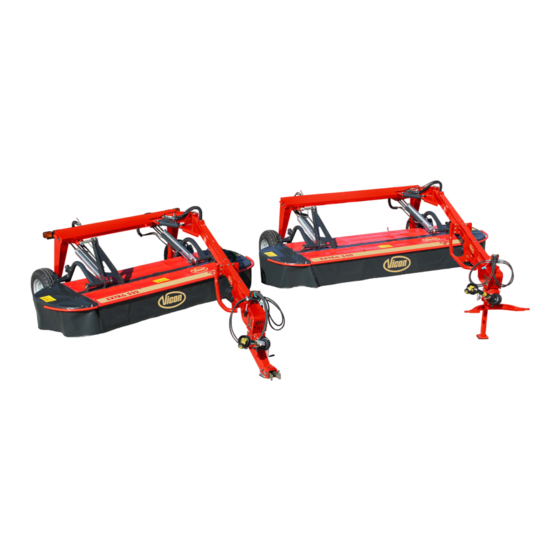
- Page 1 Technical Service Manual Trailed plain mower Extra 532-540...
- Page 2 Date 08-08-2018 Subject Vicon Extra 532 and 540 Place Kverneland Group Kerteminde AS Taarupstrandvej 25 DK-5300 Kerteminde Denmark Realized for Who it might concern Details General and operating information Additional Information...
-
Page 3: Table Of Contents
Table of contents Components General information PTO's - clutch Machine specification 4.2.1 Lifting cylinders Machine dimensions 4.2.2 Replacement cylinder(s) Safety symbols Steering cylinder Changing RPM Press relieve valve Attachment Hydraulic diagrams with functions Stetting of 540 or 1000 rpm for PTO Swivel gearbox incl. -
Page 4: Machine Specification
1.1 Machine specifications Kubota... -
Page 5: Machine Dimensions
1.1 Machine specifications Machine dimensions Machine dimensions Extra 532 Extra540... - Page 6 1.3 Safety labels US and Canada Safety symbols for the US and Canada On the machine you will find labels relating to your safety. These labels must not be removed. If the labels become illegible or detached, new labels can be ordered and affixed to the relevant areas.
- Page 7 1.3 Safety labels US and Canada Safety symbols for the US and Canada...
- Page 8 1.3 Safety labels US and Canada Safety symbols for the US and Canada...
- Page 9 1.3 Safety labels US and Canada Lighting and reflective devices - USA The machine is equipped with lighting and reflective devices as a standard, which serve to ensure safety on the roads. Lighting and reflective equipment shall be in good and sound condition at all times.
-
Page 10: Safety Symbols
1.3 Safety labels Safety symbols On the machine you will find labels relating to your safety. These labels must not be removed. If the labels become illegible or detached, new labels can be ordered and affixed to the relevant areas. - Page 11 1.3 Safety labels Safety symbols...
- Page 12 1.3 Safety labels Safety symbols Safety symbols...
-
Page 13: Changing Rpm
2.1 Setting 540 or 1000 rpm for PTO Changing the rpm Checking the rpm Checking the rpm Checking the rpm Changing the rpm Checking the rpm Checking the rpm Checking the rpm • The swivel gear's rpm can • If the swivel gear's profile on In case the RPM need to be •... -
Page 14: Stetting Of 540 Or 1000 Rpm For Pto
2.1 Setting 540 or 1000 rpm for PTO Changing the rpm Changing the rpm Changing the rpm Changing the rpm Changing the rpm Changing the rpm Changing the rpm Changing the rpm • Note; the oil-levels needs to • Rotate the transmission 180 •... -
Page 15: Attachment
2.2 Attachment to tractor Attachment of the tractor Attachment of the tractor Attachment of the tractor Attachment of the tractor Attachment of the Quick Attachment of the tractor Attachment of the Quick Attachment of the Quick Coupler. Coupler. Coupler. We have 2 standard versions; •... - Page 16 2.2 Attachment to tractor Attachment of the tractor Attachment of the tractor Attachment of the tractor Attachment of the tractor Clevis Coupler on the lower Parking stand Clevis Coupler on the lower Attachment of the Quick link crossbar link crossbar Coupler.
- Page 17 2.2 Attachment to tractor PTO length Working position lifting cylinders Hydraulic connection to tractor Hydraulic connection to tractor Two double acting valves Working position lifting cylinders PTO length Equalising the hydraulic system • The tractor must be fitted with • For lifting and lowering of the It is important that the P.T.O.
-
Page 18: Bleeding Pto
2.3 Bleeding of slip clutch Bleeding of the clutch. Bleeding of the clutch. Bleeding of the clutch. Bleeding of the clutch. Bleeding of the clutch Bleeding of the clutch The friction clutch is bled in the • Block the cutter bar by placing •... -
Page 19: First Start Up Of Machine
2.4 First start up First start-up of machine First start-up of machine First start-up of machine First start-up of machine • The side guard for the cutting • Check that the mechanical unit must be correctly safety valve is open. positioned before start up. -
Page 20: Adjusting Ground Pressure
Balancing the cutting unit Spring dimensions • The balancing of the machine's • Adjust the cutting unit's Extra 532; cutting unit should be adjusted downward pressure for both RH side; N = 42,5 – Ø10 mm. so that the downward pressure springs. -
Page 21: Setting Stubble Height
2.6 Setting stubble height. Stubble height Stubble height High skids Lower stubble height Higher stubble height High skids Shorten the top link for a lower Extend the top link for a higher High skids are needed in case stubble height stubble height you like to cut higher than around 50 mm.. - Page 22 2.6 Setting stubble height. For all models; table for selecting the skids for different cutting height! 20 mm. (0 ⁄ “) skid is for stubble 35-65 mm. (1 ⁄ ”- ”) (standard for North America) ⁄ 40 mm. (1 ⁄ ”...
- Page 23 2.6 Setting stubble height. Positions of high skids on 8 disc cutter bar North America; positions of high skids on 8 disc cutter bar North America; positions of high skids on 10 disc cutter bar Positions of high skids on 10 disc cutter bar...
-
Page 24: Maintenance
3.1 Basic instructions Basic instructions This table contains explanations of the most important terms related to maintenance. -
Page 25: Torques
3.2 Torques Torques; only for 8.8 bolts for special bolts you will find the relevant info in the operators manual and further on in this presentation. -
Page 26: Maintenance Intervals
3.3 Intervals Maintenance intervals Maintenance intervals... - Page 27 4.1 PTO PTO tractor side with coated inner tube used up to machine nr. Parts list PTO tractor side with coated inner tube KT457907 = W2300 This PTO supposed to be replaced with one with a hardened inner tube beginning of season 2017!
- Page 28 4.1 PTO PTO tractor side with hardened inner tube used from machine nr. Parts list PTO tractor side KT457907 = W2300.
- Page 29 4.1 PTO PTO tractor side with nr. A144508100 = W2400 for Clevis. Parts list PTO tractor side This W2400 has been introduced in production since 2017.
- Page 30 4.1 PTO PTO tractor side with nr. A144508000 = W2400 for 2-point hitch Parts list PTO tractor side (= 165 mm. (6 ⁄ in) longer). This W2400 has been introduced in production since 2017...
- Page 31 4.1 PTO - Clutch PTO drawbar including clutch Parts list PTO drawbar including clutch Torque 1500Nm.
- Page 32 4.1 PTO - Clutch Repair of friction clutch Repair of friction clutch Repair of friction clutch Repair of friction clutch Repair of friction clutch Repair of friction clutch Repair of friction clutch Repair of friction clutch When the torque for the friction •...
- Page 33 4.2.1 Lifting cylinder RH side Lifting cylinder RH side; KT9291800086 Seal kit A132098900...
- Page 34 4.2.1 Lifting cylinder LH side Lifting cylinder LH side; KT9291700086 Seal kit A132098800...
-
Page 35: Lifting Cylinders
4.2.1 Lifting cylinder Lifting cylinder; mechanism inside Filling of the cylinder; • Cylinder complete in = machine lifted in transport position; green pin will touch the bottom side and opens the valve to fill the cylinder with oil. • Cylinder complete out = machine on the ground in working position; (best way to do) red pin will touch the head side and will push against the purple pin to open the valve. -
Page 36: Replacement Cylinder(S)
4.3.2 Replacement lifting cylinders Changing of lifting cylinder(s) Changing of lifting cylinder(s) Changing of lifting cylinder(s) Changing of lifting cylinder(s) Changing of lifting cylinder(s) Changing of lifting cylinder(s) Changing of lifting cylinder(s) Changing of lifting cylinder(s) • Lower the cutting unit of the TIP! Measure the settings of the •... - Page 37 4.3 Replacement lifting cylinders Changing of lifting cylinder(s) Changing of lifting cylinder(s) Changing of lifting cylinder(s) Changing of lifting cylinder(s) Changing of lifting cylinder(s) Changing of lifting cylinder(s) • Tighten the springs on both • Activate the hydraulic system of •...
-
Page 38: Steering Cylinder
4.3 Steering cylinder Steering cylinder Seal kit KT99413163... -
Page 39: Press Relieve Valve
4.4 Inline relieve valve. Inline relieve valve. How to set inline relieve valve. • The in line relief valve is factory set to open at 90 bar (1300 PSI) at 50 l/min (13,2 gallon) • For resetting the valve; Inline relieve valve. A. -
Page 40: Hydraulic Diagrams With Functions
4.5 Hydraulic diagrams. Hydraulic diagram - steering cylinder goes out to working position with unit in transport position *Master slave cylinders for lifting the cutting unit. *No restrictors in this system, the long 3/8 "hydraulic lines provide the necessary restriction. - Page 41 4.5 Hydraulic diagrams. Hydraulic diagram - lifting cylinder goes out to bring unit downwards in working position...
- Page 42 4.5 Hydraulic diagrams. Hydraulic diagram - lifting cylinder goes in to bring unit upwards in working position...
-
Page 43: Swivel Gearbox Incl. Repair Instructions
4.6 Details swivel gearbox Swivel gearbox A132098430 Swivel gearbox A132098430... - Page 44 4.6 Repair of swivel gearbox Disassembly of A132098430 Disassembly of A132098430 Disassembly of A132098430 Disassembly of A132098430 Tools : Fork wrench n° 13-17-19, Tools : Chisel, hammer, snap • Hit the shaft (10), from side • Unscrew bolts (19) (A) in order to extract it from pliers, chisel, disassemble housings ring pliers,...
- Page 45 4.6 Repair of swivel gearbox Disassembly of A132098430 Disassembly of A132098430 Disassembly of A132098430 Disassembly of A132098430 • Disassemble oil seal (30), cap • Unbend cotter pins (21) and • Unscrew locknut (13) using Tools : Hammer, extractor, adjustable wrench and take (29), using a chisel and chisel, snap ring pliers, pliers, remove it, using a pliers.
- Page 46 4.6 Repair of swivel gearbox Assembly of A132098430 Disassembly of A132098430 Disassembly of A132098430 Disassembly of A132098430 Tools : Extractor, chisel, pipe, Tools : Pipe, hammer, adjustable • Disassemble outer rings (18), Clean all the components from hammer. using an extractor. wrench, torque meter.
- Page 47 4.6 Repair of swivel gearbox Assembly of A132098430 Assembly of A132098430 Assembly of A132098430 Assembly of A132098430 Tools : Pipe, hammer, adjustable • Assemble protective washer • Apply adhesive tape on • Assemble pre-mounted shaft wrench, pliers torque meter, snap (15) and inner ring (18) using extension threads (9) in order (11), inside extension (14),...
- Page 48 4.6 Repair of swivel gearbox Assembly of A132098430 Assembly of A132098430 Assembly of A132098430 Assembly of A132098430 • Assemble inner ring (16) on • Assemble inner ring (16) on • Assemble outer ring (16), Tools : Pipe, hammer, snap ring shaft (10), using pipe and using pipe and hammer, snap pliers, torque meter.
- Page 49 4.6 Repair of swivel gearbox Assembly of A132098430 Assembly of A132098430 Assembly of A132098430 Assembly of A132098430 Tools : Fork wrench n° 13-17-19, • In order to have the correct • Verify the right mesh between • Assemble plugs (25),(26) and backlash, change shims set tighten max.
- Page 50 4.6 Repair of swivel gearbox Technical specifications A) The contact of crown wheel and pinion must be located like in Fig. A ( mark obtained without load on bevel gears ) Use the shims in order to obtain the right contact. Note : If the right contact is obtained, but the backlash is out of the request range, move the crown wheel by adding or taking away shims.
-
Page 51: Bevel Gearbox Incl. Repair Instructions
4.7 Details Gearbox machine side Bevel gearbox KT91635000 complete Bevel gearbox KT91635000 complete what is including the sealing ring KT9195500061 for the shaft (see X and page 57) (see also page 57) - Page 52 4.7 Repair of Gearbox machine side Disassembling bevel gearbox Disassembling bevel gearbox Disassembling bevel gearbox Disassembling bevel gearbox Disassembling bevel gearbox Disassembling bevel gearbox Disassembling bevel gearbox Disassembling bevel gearbox Warning : Disassembled shims, Tools : Fork wrench n°13-17-19- • Unscrew bolts (4), •...
- Page 53 4.7 Repair of Gearbox machine side Disassembling bevel gearbox Disassembling bevel gearbox Disassembling bevel gearbox Disassembling bevel gearbox Disassembling bevel gearbox Disassembling bevel gearbox Tools : Hammer, chisel, pipe, • Disassemble snap ring (17), • Hit the pinion shaft from side extractor, pliers, snap ring pliers, shim (15),(19).
- Page 54 4.7 Repair of Gearbox machine side Assembling bevel gearbox Assembling bevel gearbox Assembling bevel gearbox Assembling bevel gearbox Assembling bevel gearbox Assembling bevel gearbox Assembling bevel gearbox Assembling bevel gearbox Clean all the components from Tools : Pipe, hammer, snap ring •...
- Page 55 4.7 Repair of Gearbox machine side Assembling bevel gearbox Assembling bevel gearbox Assembling bevel gearbox Assembling bevel gearbox Assembling bevel gearbox Assembling bevel gearbox Assembling bevel gearbox Assembling bevel gearbox Tools : Snap ring pliers, pipe, • Assemble shim (6), snap ring •...
- Page 56 4.7 Repair of Gearbox machine side Assembling bevel gearbox Assembling bevel gearbox Assembling bevel gearbox Fig. A Fig. A Assembling bevel gearbox Assembling bevel gearbox Assembling bevel gearbox • Assemble cap (10), oil seals A) The contact of crown wheel C) Tightening of bolts must be (2) using a pipe and hammer.
- Page 57 4.7 Repair of Gearbox machine side Assembling bevel gearbox Assembling bevel gearbox Assembling bevel gearbox Assembling bevel gearbox Assembling seal ring Assembling seal ring Assembling seal ring Assembling seal ring KT9195500061 KT9195500061 KT9195500061 KT9195500061 • Extra seal ring supplied with •...
-
Page 58: Cutter Bar Details
4.8 Cutter bar-details Cutter bar up to machine nr. KT480197 Cutter bar – part numbers up to machine nr. KT480197 Nr. 1 and 2 are BOM nrs. of a kit including a box, info, bolts, nuts etc. so not the same numbers as on next page what is just the hub itself. - Page 59 4.8 Details hub Hub drive line side up to machine nr. KT480197 Hub for the rest up to machine nr. KT480197...
- Page 60 4.8 Details hub Contents of a spare part kit for bearing house KT55243300 PTO side Contents of a spare part kit for bearing house KT55245300 (That is including an A-info showing how to do the job.) (That is including an A-info showing how to do the job.)
- Page 61 4.5 Cutter bar-details Cutter bar with new hubs from machine nr. KT480197 Cutter bar – part numbers Latest model from machine nr. KT480197 has the new style hubs what cannot be repaired! NB! As spare part you can only order a complete hub and no longer parts like bearing, gearwheel , housing, etc.
- Page 62 Latest model from machine nr. KT480197 4.5 Cutter bar-details has the new style hubs what cannot be repaired! Contents of a spare part kit for bearing house A144143930 on PTO Contents of a spare part kit for bearing house A144144030. From side.
- Page 63 Latest model from machine nr. KT480197 5.4.1 Cutter bar details has the new style hubs what cannot be repaired! Standard hub A144144030 and A144143930 for PTO side. From machine nr. KT480197 Note; old hubs will still fit on new cutter bars and new hubs on old cutter bars.
- Page 64 Latest model from machine nr. KT480197 4.5 Cutter bar-details has the new style hubs what cannot be repaired! Standard hub A144144030 and A144143930 for PTO side. From Part descriptions machine nr. KT480197 Standard Hub PTO side has 4 extra tap holes in flange...
-
Page 65: Cutter Bar Repair Instructions
4.8.1 Cutter bar-repair instructions Removing cutter bar out of unit Removing cutter bar out of unit Removing cutter bar out of unit Removing cutter bar out of unit Removing cutter bar out of Removing cutter bar out of Removing cutter bar out of Removing cutter bar out of unit unit... - Page 66 4.8.1 Cutter bar-repair instructions Assembly of cutter bar Removing cutter bar out of unit Assembly of cutter bar Assembly of cutter bar Assembly of cutter bar Removing cutter bar out of Assembly of cutter bar Assembly of cutter bar unit •...
- Page 67 4.8.1 Cutter bar-repair instructions Cutter bar repair Cutter bar repair Cutter bar repair Cutter bar repair Removing bearing houses Removing bearing houses Removing bearing houses Removing bearing houses • Place a suitable receptacle • Remove the bolts and nuts • Use tool T7 as shown and •...
- Page 68 4.8.1 Cutter bar-repair instructions Cutter bar repair Cutter bar repair Cutter bar repair Cutter bar repair Change of bearing Removing intermediate Removing intermediate Removing intermediate gearwheel gearwheel intermediate gearwheel gearwheel • Remove bolt “C” on the under • Use a longer bolt of the same •...
- Page 69 4.8.1 Cutter bar-repair instructions Cutter bar repair Cutter bar repair Cutter bar repair Cutter bar repair Change of bearing Change of bearing Change of bearing Change of bearing intermediate gearwheel intermediate gearwheel intermediate gearwheel intermediate gearwheel • Remove tool T1 from the gear •...
- Page 70 4.8.1 Cutter bar-repair instructions Cutter bar repair Cutter bar repair Cutter bar repair Cutter bar repair Assembly of intermediate Change of bearing Change of bearing Assembly of intermediate intermediate gearwheel gearwheel gearwheel intermediate gearwheel • Place tool T1 on top of the •...
- Page 71 4.8.1 Cutter bar-repair instructions Cutter bar repair Cutter bar repair Cutter bar repair Cutter bar repair Assembly of bearing house(s) Assembly of intermediate Assembly of intermediate Assembly of bearing house(s) gearwheel gearwheel • The lock bolt is provide with • Tighten the lock bolts to 90 •...
- Page 72 4.8.1 Cutter bar-repair instructions Cutter bar repair Cutter bar repair Cutter bar repair Cutter bar repair Assembly of bearing house(s) Assembly of bearing house(s) Assembly of bearing house(s) Assembly of bearing house(s) • Add grease on the bushings • Fit the bolts. •...
- Page 73 Cutter bar No. of disc Ltr. US Pints Imp. Pints Extra 532 • Fit the bearing units on the Extra 540 cutter bar. • Remove tool T6 after fitting of the bearing units.
- Page 74 4.8.1 Cutter bar-repair instructions Cutter bar repair Cutter bar repair Cutter bar repair Cutter bar repair Assembly of bearing house(s) Assembly of bearing house(s) Assembly of bearing house(s) Assembly of bearing house(s) • Fit the last bearing unit in the •...
-
Page 75: Cutter Bar Maintenance
4.8.2 Cutter bar-maintenance PTO shaft cutter bar Cone Discs Blades Torque 90 Nm (67 ft /lb) Torque discs Torque PTO Torque Cone Torque blade bolts • Apply Loctite 242 or a similar • Apply Loctite 242 or a similar • Apply Loctite 242 or a similar •... - Page 76 4.8.2 Cutter bar-maintenance Anti Wrap Device Anti Wrap Device Anti Wrap Device Anti Wrap Device Assembly instructions Assembly instructions Assembly instructions Assembly instructions NB! Older models had a steel • Fit the two bracket shown at the • Fit the top protection. •...
- Page 77 4.8.2 Cutter bar-maintenance Blade bolts Quick fit Alignment discs Wearing soles/skids How to check alignment discs Wearing bolts Wearing quick fit How to check wearing of soles • If the machine is fitted with • Inspect the timing of the discs. •...
-
Page 78: Cutter Bar; Changing Oil
10 - 15 minutes. For the cutter bar always use • Fit the oil plug and tighten it SAE GL4 EP 80 securely on the cutter bar. Cutter bar No. of disc Ltr. US Pints Imp. Pints Extra 532 Extra 540... -
Page 79: Bevel Gearbox; Changing Oil
4.9 Oil change gearboxes Bevel gear changing oil Bevel gear changing oil Bevel gear changing oil Bevel gear changing oil Bevel gear changing oil Bevel gear changing oil After the first 50 hrs. thereafter • Remove the dipstick. • Decal with all information's what you can find on the every 200 hours or once a year. -
Page 80: Swivel Gearbox; Changing Oil
4.9 Oil change gearboxes Swivel gear changing oil Swivel gear changing oil Swivel gear changing oil The upper part of the swivel The upper part of the swivel The lower part of the swivel hitch hitch hitch After the first 50 hrs. thereafter •... -
Page 81: Lubrication
4.10 Lubrication Lubrication every 40 hours. Note; a too dry shaft and yoke will give too much load on the bearings inside the hub on top of the cutter bar, the cutter bar housing itself and the gearbox! - Page 82 4.10 Lubrication Lubrication every 100 hours. Lubrication as required.
-
Page 83: Wheel Info Incl. Torque And Hub Info
4.11 Wheel and wheel-hub info Wheel info Wheel info After the first 10 hours; • Use a suitable torque wrench adjusted to the torque shown in the table below. • Place the wrench on the wheel bolts. • Check all the bolts on the wheels and tighten them to the torque shown. -
Page 84: Options
5.0 Options High skids Lighting kit Quick release of knives Blade stops High skids Lighting kit Quick release of knives Blade stop • High skids are needed in case • The machine can be fitted • Standard for the US and •... - Page 85 5.0 Options Cones for better flow Safety chain for road transport Hitch on the tractor lifting arms Hitch on the lower link crossbar Cones for better flow Safety chain for road transport Hitch on the tractor lifting arms Hitch on the lower link crossbar •...
- Page 86 5.0 Options Swath disc LH side 21 spline yoke 1 3/8 “ Straw dividers Swath disc RH side Swath disc LH side 21 spline yoke 1 3/8 “ Straw dividers Swath disc RH side • To create a clean area between •...
- Page 87 5.0 Options Wheels for NA Cutter bar protection Wheels for NA Cutter bar protection • To protect discs on outer ends of cutter bar against stones etc..
-
Page 88: Troubleshooting
6.0 Trouble shooting Hydraulic system... - Page 89 6.0 Trouble shooting Cutter bar • [1] Problems with stripes are more likely to occur when mowing short, strong, spring crops in less than ideal weather conditions. Always begin by checking that the knives on the cutting discs are sharp. •...
- Page 90 6.0 Trouble shooting...
Need help?
Do you have a question about the Extra 532 and is the answer not in the manual?
Questions and answers