
Related Manuals for Vicon Extra 532


Summary of Contents for Vicon Extra 532
- Page 1 Extra 532 - 540 Operator‘s manual Translated from the original instruction manual Revision Date printed 08.2021 Language Machine number KT499850 Document number A132101500 Index 2021-08...
- Page 2 Tel./fax: +45 65 19 19 00 / +45 65 19 19 99 web: www.kvernelandgroup.com By registering your Vicon product at my.vicon.eu you will benefit from easy access to Vicon‘s online service tools and updated information. Copyright by Kverneland Group Kerteminde AS, Denmark. Reproduction, transfer to other media, translation or the use of extracts or parts of this manual without the explicit permission of Kverneland, is not permitted.
-
Page 3: Table Of Contents
Table of contents Table of contents Contents ............ Parking and Storage ......... Target group Before storage The meaning of the symbols Parking/disconnection Storage Safety ............For your own safety Maintenance ..........Lighting equipment For your own safety Who can operate the machine? General instructions General safety instructions After 50 hours of use... -
Page 4: Contents
Contents Target group Contents Simplified illustrations to improve understanding All of the illustrations of the machine in this instruction manual show it without the guards or with the protective equipment open to improve understanding. Ensure that the safety instructions are complied with and the instructions in the instruction manual are followed. -
Page 5: The Meaning Of The Symbols
Contents The meaning of the We have used different symbols to make the text clear. An explanation follows: symbols • A dot symbol marks a list of instructions or information. A triangle marks an action you must carry out. ... -
Page 6: For Your Own Safety
Safety For your own safety Know your equipment and its limits. Read the manual through Safety before attempting to start up and operate the unit. This chapter includes general safety instructions. In addition, each chapter in the instruction manual includes specific safety instructions not set out here. - Page 7 Safety Safety symbols On the machine you will find labels relating to your safety. These labels must not be removed. If the labels become illegible or detached, new labels can be ordered and affixed to the relevant areas.
- Page 8 Safety The meaning of the symbols Read the instruction manual Read and understand all safety instructions in the instruction manual. Do not start and/or operate the machine until you have read all the safety instructions in the instruction manual. Starting and/or operating the machine without understanding all the safety instructions can cause serious injury or death.
- Page 9 Safety Risk of crushing the fingers and hands - force from the sides Risk of crushing fingers and hands any time the machine's parts are moving. Keep fingers and hands out of the hazard area until the machine's parts have stopped moving. Crushing of fingers and hands can cause serious injury.
-
Page 10: Lighting Equipment
Safety Lighting equipment Checking the electric cable Check the electric cable. The insulation of the electric leads must not be unduly worn, and the cables must not be hanging loose. Electric cables with cable insulation that is missing or worn through must be replaced. - Page 11 Safety ISO 1724 connector - overview Cable connection for: Yellow Left-hand indicator (amber) Blue Not used White Earth; all lights Green Right-hand indicator (amber) Brown Right-hand rear light (red) / Reg. plate (white) Brake light (red) Black Left-hand rear light (red) ...
-
Page 12: Who Can Operate The Machine
Safety Who can operate the Qualified machine operators Minors under the age of 16 must not operate the machine. The machine? machine must only be operated, serviced or repaired by persons who hold the required qualifications and have been informed of the risks relating to handling of the machine. - Page 13 Safety Check the surrounding area before starting to use machine Check the surrounding area before driving and using the machine. This prevents persons and animals in the vicinity from being harmed. If the surrounding area is not checked, it may result in serious injuries to persons or animals.
-
Page 14: Connecting
Safety Connecting Correct attachment of the machine The machine must be correctly connected, following the instructions. The machine can be detached from the tractor if the connection is not carried out properly. Incorrect attachment can lead to accidents. When attaching the machine to the tractor you must therefore: •... - Page 15 Safety Be careful when working around the PTO shaft When working on the PTO shaft, the tractor PTO outlet must be disconnected, the tractor must be stopped and the ignition key removed. This prevents the PTO shaft from suddenly starting to rotate. If the tractor and the PTO shaft have not been connected in accordance with the instructions, serious accidents causing damage to limbs can occur.
-
Page 16: Hydraulic
Safety Hydraulic Only connect hydraulics when the system is depressurised You should only connect the hydraulic hoses to the tractor's hydraulics when the hydraulic system on both the tractor and the machine is depressurised. There is a risk that the machine will move accidentally. Unintentional movement of the machine may result in serious injuries. - Page 17 Safety Replacing the hydraulic hoses Replace the hydraulic hoses at least once every 6 years. Hydraulic hoses also wear without any visible damage. Only use hydraulic hoses with identical technical specifications. The necessary data is printed on the hydraulic hose. Defective hydraulic hoses may cause serious or fatal injury.
-
Page 18: Load Capacity
Safety Load capacity Compliance with total weight, axle pressure, carrying capacity of the tyres, and minimum tractor load Neither the tractor's total weight, axle pressure or the carrying capacity of the tyres may be exceeded with front mounted and rear mounted machines. -
Page 19: Transport On Public Roads
Safety Transport on public Check that the machine complies with all national and local requirements regarding transport on public roads roads When driving on public roads, the machine must comply with the Road Traffic Act's current requirements. This ensures your safety and that of other road users. - Page 20 Safety Risk of instability when heavy hitched implements are used in the raised position Drive carefully when heavy hitched implements are used in the raised position. There is a high risk of the machine overturning. This can result in serious injuries or death. Carrying passengers on the machine is prohibited It is dangerous and illegal to carry passengers on the machine.
-
Page 21: Use
Safety Keep away from thunder and lightning Avoid driving with the machine or working on the machine in a thunder and/or lightning storm. There is a high risk of being struck by lightning. Lightning can cause serious injuries or death. Risk of instability when heavy hitched implements are used in the raised position Drive carefully when heavy hitched implements are used in the raised... - Page 22 Safety Carrying passengers on the machine is prohibited It is dangerous and illegal to carry passengers on the machine. The machine is not approved for personal transportation. Transporting persons on the machine may result in serious injuries and death. Check the surrounding area before starting to use machine Check the surrounding area before driving and using the machine.
- Page 23 Safety Checking bolts on moving parts Check that all bolts on moving parts are correctly tightened. Tightening parts prevents moving parts jarring. Parts which are not correctly tightened can work loose and damage the machine. Maintain the rotational speed on the tractor PTO outlet The prescribed rotational speed for the PTO shaft must not be exceeded.
-
Page 24: Disconnection
Safety Disconnection Increased risk of injury when disengaging There is an increased risk of injury when disengaging the machine from the tractor. Following the above instructions will protect you and others from injury. Failure to follow the above instructions may result in serious injuries. -
Page 25: Maintenance
Safety Maintenance Comply with the service and maintenance intervals given in the instructions Comply with the intervals for service and maintenance as given in the instructions. By complying with the maintenance intervals you ensure that the machine will operate without malfunctions and provide maximum protection for the environment. - Page 26 Safety Disconnect the power source when working on the electrical systems Always disconnect the negative battery terminal before you start working on the electric system. This will prevent short circuits and damage to the electric circuit. Be careful when cleaning with high pressure cleaning equipment Only use low pressure cleaning equipment to clean bearings, hydraulic hoses, plastic components, electrical control boxes and electrical equipment.
-
Page 27: Further Safety Instructions
Safety Further safety instruc- Follow the instructions when working on the machine The machine safety instructions should always be complied with. This tions will protect you and others from injury. Failure to follow the safety instructions may result in serious injuries. In addition to the safety instructions the following should be complied with: •... -
Page 28: Field Of Application
The machine This chapter includes general information about your machine. The machine Field of application 532 - 540 is a trailed mower intended for mowing common grass and cereal crops. The instructions for use are given in the following chapters. Correct usage of the The machine can be used in fields for mowing the following crops: •... -
Page 29: Machine Characteristics
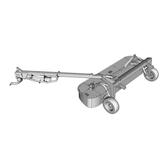
The machine Machine Description of the machine 532 - 540 is a trailed mower which operates on the tractor's right-hand characteristics side. The machine is trailed behind the tractor via a drawbar which is coupled to the tractor's lift arms. The drawbar is connected to the main frame of the machine which carries the whole machine on 2 powerful wheels. -
Page 30: Synopsis
The machine Synopsis Hydraulic cylinder Swivel hitch Cutting unit Main frame Drawbar Support leg Spring Guard Drawbar tongue PTO shaft Main gear... -
Page 31: Dimensions
The machine Dimensions... - Page 32 The machine Dim. Unit 4530 5000 4220 4900 3380 1530 3200 4000 2690 3450 3970 4730 1450...
-
Page 33: Weight
The machine Weight Load Load Axle Coupling point Model Load Load Total weight Axle Coupling point 1220 1340... -
Page 34: Specifications
The machine Specifications Specification Unit Unladen weight 1220 1340 PTO (Power takeoff) 540/1000 Power requirement Number of cutting discs parts Number of knives parts RPM, cutting discs 3000 Stubble height 20-100 Hydraulic flow min/max l/min 15 - 50 Hydraulic pressure min/max 90 - 200 Working width Speed during operation... -
Page 35: Tractor Requirements
The machine Tractor requirements Tractor weight and size The tractor must be of the appropriate size for its weight. Local legislation governing this ratio must be observed. The correct ratio between tractor and machine ensures correct braking functions and manoeuvrability. An incorrect ratio between tractor and machine can be dangerous. -
Page 36: Preparation
Preparation Preparing the machine The machine is divided into its main components for transport to the Preparation user. The machine must be assembled in accordance with the specific assembly instructions delivered with each machine. Do not attempt to assemble the machine alone Personnel must be trained before assembling the machine. -
Page 37: Pto Shaft Length
Preparation PTO shaft length Stopping the tractor and preventing it from rolling Before uncoupling: Stop the tractor. Remove the ignition key. Secure the tractor to prevent it from rolling. Failure to secure the tractor to prevent it from rolling could endanger lives. - Page 38 Preparation Shortening the PTO shaft Refer to the manufacturer's user manual delivered with the PTO shaft. »User manual for the PTO shaft« Page 37 Minimum 20 mm Minimum 200 mm Fitting the PTO shaft Ensure that the PTO shaft is fitted in the correct position. This is indicated by a marking on the PTO shaft's protective tube.
-
Page 39: Swivel Hitch
Preparation Swivel hitch Checking the rpm Maintain the rotational speed on the tractor PTO outlet It is dangerous to connect a tractor with PTO = 1000 rpm to a machine intended for PTO running at 540 rpm. The machine is not designed for this speed. - Page 40 Preparation The swivel gear's rpm can also be checked by observing the gear's pivot joint. Check the swivel gear in the following way: Observe the gear's profile in the middle of the swivel gear. • If the swivel gear's profile on the lower part of the swivel gear is wide, the machine should be run at a rotational speed of 1000 rpm.
- Page 41 Preparation 1000 RPM If the machine is to be fitted to a tractor's PTO shaft running at 1000 RPM, the following procedure must be followed: Remove the PTO shaft. Remove the bolts shown on both sides of the transmission. Bracket ...
- Page 42 Preparation Remove the bolts shown on both sides of the transmission. Bolt Remove the transmission. Air release plug Remove the air release plug and the oilplug and switch them over. Remove the adapter for the PTO shaft. Oilplug Adapter...
- Page 43 Preparation Rotate the transmission 180 degrees. Bolt Fit the transmission. Do not forget the lock plate. Fit the bolts on both sides of the transmission Tighten all bolts to a torque of 225 Nm. Fit the adapter. 225 Nm Adapter Lock plate...
- Page 44 Preparation Fit the bracket. Bracket Fit the bolts on both sides of the transmission. Tighten all bolts to a torque of 225 Nm. 225 Nm Bolt Force the corners of the lock plate back in against all the bolt heads.
- Page 45 Preparation Tool box The machine is equipped with a tool box for storing standard hand tools, extra knives, etc. The tool box is used as follows: Remove the pin. Pull the took box out. The tool box can be used to store standard hand tools, extra knives, etc.
-
Page 46: Connecting
Connecting Attachment of the Connecting tractor Coupling a tractor and a machine There is an increased risk of injury when attaching the machine to the tractor. Attention to the task will ensure your safety and that of others. Failure to follow the safety instructions may result in serious injuries. - Page 47 Connecting Check that the tyre pressure for the tractor's rear wheels is correct. Lifter »Check the tyre pressure regularly« Page 23 • As the starting point: Adjust the right and left lift arms so they are at the same height. If the tractor is equipped with a swivelling lower link crossbar: ...
- Page 48 Connecting Lock the lift arms with a chain* between the lift arm and highest point. * Optional equipment. »Extra equipment« Page 117 Chain* Check the length of the PTO shaft and adjust if necessary. »PTO shaft length« Page 37 ...
-
Page 49: Hydraulic
Connecting Hydraulic Safety Only connect hydraulics when the system is depressurised You should only connect the hydraulic hoses to the tractor's hydraulics when the hydraulic system on both the tractor and the machine is depressurised. There is a risk that the machine will move accidentally. - Page 50 Connecting Hydraulic connection Checking that the hydraulic system is correctly connected Ensure that the hydraulic system is correctly connected. Otherwise, this can cause injuries, and damage to the machine. Stop the tractor and remove the ignition key. Drawbar The tractor must be fitted with 2 sets of double acting hydraulic outlets, which are connected as follows: Hydraulic hose for: Function...
-
Page 51: First Start-Up
Connecting First start-up The initial test drive of the machine is important When the machine is connected to the tractor for the first time it must be test driven. Attention to the task will ensure your safety and that of others. Failure to follow the safety instructions may result in serious injuries. - Page 52 Connecting Checking the cutting unit Equalising the hydraulic system After a prolonged period without use with the cutting unit raised, there is a risk that the machine's cutting unit may sink unevenly in the machine's hydraulic cylinder. This means that the cutting unit is not parallel with the machine's main frame.
-
Page 53: Transport Position
Connecting Transport position Check the surrounding area before starting to use machine Check the surrounding area before driving and using the machine. This prevents persons and animals in the vicinity from being harmed. If the surrounding area is not checked, it may result in serious injuries to persons or animals. - Page 54 Connecting Pull the elastic cord out over both ends of the guard as shown. This prevents the tarpaulin from flapping during transportation. Pull out and release the lock for the guard. Swivel both guards upwards as shown.
-
Page 55: Operation
Operation Safety Operation The operator should receive careful instructions before using the machine The machine should only be used if the operator has been given thorough instructions. Thorough machine instruction allows safe usage. Insufficient instructions can result in wrong usage of the machine and accidents. -
Page 56: Working Position
Operation Working position The machine is operated in the following way: Make sure that there are no persons in the surrounding area. Fasten all the guards on the machine. Check that the side guard on the cutting unit is folded out and correctly positioned. -
Page 57: Stubble Height
Operation Stubble height The stubble height is adjusted in the following way: • Making the top link longer reduces the stubble height. • Making the top link shorter increases the stubble height. Top link The stubble height can be combined with fitting high skids* which can be used to set the stubble height as follows: Stubble height Note... -
Page 58: Balancing
Operation Balancing The balance of the machine's cutting unit should be adjusted so that the downward pressure on the machine's cutting unit is about 40-60 The balancing of the cutting unit is adjusted in the following way: Undo the counter nuts with the springs on both sides of the machine. -
Page 59: Working In The Field
Operation Working in the field Check the surrounding area before starting to use machine Check the surrounding area before driving and using the machine. This prevents persons and animals in the vicinity from being harmed. If the surrounding area is not checked, it may result in serious injuries to persons or animals. - Page 60 Operation Check that the hydraulic mechanical safety valve is open. Valve Connect the tractor's PTO outlet. Carefully increase the speed on the PTO shaft to 540/1000 RPM. »RPM on the PTO outlet« Page 40 Activate the tractor hydraulics and turn the machine's drawbar to the right side of the tractor.
- Page 61 Operation Activate the tractor hydraulics and raise the cutting unit when turning at the headland. Activate the tractor hydraulics and lower the cutting unit of the machine to its working position. Activate the tractor hydraulics until the hydraulic cylinders on the cutting unit are fully extended to their maximum length.
-
Page 62: Transport On Public Roads
Transport on public roads Safety Transport on public roads Read the safety instructions carefully before driving on public roads You must read the safety instructions carefully before driving on a public road. »Transport on public roads« Page 19 This will ensure that dangerous situations and accidents are avoided. -
Page 63: Check
Transport on public roads Check Before travelling on the road the machine should be checked according to this check list: Is the machine in the transport position? Is the mowing device lifted all the way up? Are the machine side guards folded in? ... -
Page 64: Before Cleaning
Cleaning Before cleaning Cleaning Higher risk when cleaning the equipment When cleaning, there is an increased risk of injury. Paying attention when carrying out cleaning work will ensure your safety and that of others. Failure to follow the safety instructions may cause serious injuries. -
Page 65: Cleaning
Cleaning Cleaning Use the correct cleaning agents Use only PH neutral cleaning agents when cleaning the machine. PH neutral cleaning agents give your machine maximum protection. Cleaning agents with either a high or low PH value can corrode plastic, rubber and varnished surfaces. •... -
Page 66: Parking And Storage
Parking and Storage Before storage At the end of the season, the machine should be prepared for storage: Parking an d Storage Check and tighten all bolts. »Torque moment« Page 126 Repair any damaged components. Replace any defective components. ... - Page 67 Parking and Storage Hydraulic Only disconnect hydraulics when the system is depressurised You should only disconnect the hydraulic hoses from the tractor's hydraulics if the hydraulic systems on both tractor and machine are depressurised. There is a risk that the machine will move accidentally.
-
Page 68: Storage
Parking and Storage Storage At the end of the season, the machine should be prepared for storage: Carry out the following: • Clean the machine thoroughly. »Cleaning« Page 64 • Change the oil in all the machine's transmissions. »Lubricants« Page 125 •... -
Page 69: Maintenance
Maintenance For your own safety Maintenance Comply with the service and maintenance intervals given in the instructions Comply with the intervals for service and maintenance as given in the instructions. Complying with the maintenance intervals will ensure that the machine operates without malfunctions, preventing injury and offering maximum protection of the surroundings. - Page 70 Maintenance Lubrication safety and use of oil Oils and lubricants contain additives that under certain circumstances can have serious consequences for your health. Therefore, when using oil and lubricants be aware of the following: • Avoid direct contact with these agents. They can damage the skin.
-
Page 71: General Instructions
Maintenance General instructions These instructions concern general maintenance work. Specific maintenance work procedures for each machine will be described later. When performing any maintenance work the machine must be secured in the transport position. If the work position is necessary for performing maintenance work, you will find appropriate instructions to cover this. - Page 72 Maintenance Maintenance intervals • Hydraulic hoses every 6 years • • Knives • • • • Cutting disc • • • • Stone guard and counter knife • • • • Tarpaulin • • • After 50 working hours • •...
- Page 73 Maintenance Safety in connection with maintenance work on the machine When working on the machine the tractor must be stopped and secured. This prevents the PTO shaft from suddenly starting to rotate. Failure to follow the safety instructions may result in serious injuries.
- Page 74 Maintenance Swivel hitch Only to be performed if the swivel gear has been removed and inverted. »RPM on the PTO outlet« Page 40 The oil level is checked as follows: The upper part of the swivel hitch Remove oilplug 2. ...
- Page 75 Maintenance The lower part of the swivel hitch Oilplug 4 Remove oilplug 5. Check that the oil is filled all the way up to the hole. When topping up, remove oilplug 4. Fill the oil through the hole for oilplug 4. •...
-
Page 76: After 50 Hours Of Use
Maintenance After 50 hours of use Safety in connection with maintenance work on the machine When working on the machine the tractor must be stopped and secured. This prevents the PTO shaft from suddenly starting to rotate. Failure to follow the safety instructions may result in serious injuries. -
Page 77: Daily
Maintenance Daily Safety in connection with maintenance work on the machine When working on the machine the tractor must be stopped and secured. This prevents the PTO shaft from suddenly starting to rotate. Failure to follow the safety instructions may result in serious injuries. -
Page 78: Knives
Maintenance Knives Check the machine knives on a regular basis The machine's knives must be regularly inspected. Worn or damaged knives can unbalance the rotating parts. Vibrations can cause damage to the machine. »Maintenance intervals« Page 72 The knives are checked as follows: ... - Page 79 Maintenance Pull out and release the lock for the guard. Open the machine's front guard. 95 Nm +/- 5 Turn the cutting discs by hand until the damaged knife is in the position shown. Inspect the condition of the knives for wear. ...
- Page 80 Maintenance If the machine is fitted with knife quick release*, the same requirement applies for bolt wear. »Knives« Page 104 * Extra equipment »EXPRESS« Page 117. Min. 16 mm Knife Spring Pull out and release the lock for the guard. ...
- Page 81 Maintenance Open the mechanical safety valve. Valve...
-
Page 82: Cutting Disc
Maintenance Cutting disc »Maintenance intervals« Page 72 The cutting discs are checked as follows: Inspect the condition of the cutting discs for deformities and cracks. Damaged and/or deformed cutting discs must be replaced 80 Nm +/- 5 immediately. ... - Page 83 Maintenance Cone Check the machine cones on a regular basis The machine's cones must be checked and cleaned regularly. Build-up of crop waste can cause imbalance in the rotating parts. Vibrations can cause damage to the machine. »Maintenance intervals« Page 72 An external check of the cones is carried out in the following way: ...
-
Page 84: Stone Guard And Counter Knife
Maintenance Stone guard and counter knife Correct support of the machine is necessary to prevent injury The machine must be properly supported when work is being carried out underneath it. If the machine is not correctly supported, there is a high risk that it may overturn, causing injury. If the machine is not sufficiently supported, this can result in serious or even fatal injuries. - Page 85 Maintenance Carry out a visual inspection of the machine's stone guard and counter knife for wear. Stone guards and counter knives with visible holes caused by heavy wear must be replaced immediately. »Stone guard and counter knife« Page 110 ...
-
Page 86: Tarpaulin
Maintenance Tarpaulin The tarpaulin and other guards around the cutting unit must be checked regularly. The tarpaulin and other guards are checked as follows: Visually inspect the machine's guards for holes and other damage. Any guards with visible holes or other damage must be replaced immediately. - Page 87 Maintenance Wheel Do not drive on tyres which are worn or damaged Do not drive on tyres which are worn or damaged. Replace worn or damaged tyres with tyres with the same specifications. There is an increased risk of accidents when driving on public roads with tyres in this condition.
-
Page 88: Every 200 Hours Of Use
Maintenance Every 200 hours of use or once a year Safety in connection with maintenance work on the machine When working on the machine the tractor must be stopped and secured. This prevents the PTO shaft from suddenly starting to rotate. -
Page 89: Cutterbar
Maintenance Cutterbar »Maintenance intervals« Page 72 The oil in the cutterbar is changed as follows: Place a wooden block or similar under the right-hand wheel of the machine so that the machine tilts slightly to the left. Activate the tractor hydraulics and raise the machine's cutterbar fully. - Page 90 Maintenance Pull out and release the lock for the guard. Open the machine's front guard. Locate oilplugs 1 and 2 on the cutterbar and clean the area. Remove oilplugs 1 and 2. Let the oil flow into a suitable container. ...
-
Page 91: Main Gear
Maintenance Main gear »Maintenance intervals« Page 72 The oil is changed as follows: The oil is changed as follows: Remove the oilplug. Let the oil flow into a suitable container. Allow the last of the oil to drip out of the transmission for approx. 10 - 15 minutes. - Page 92 Maintenance Swivel hitch The upper part of the swivel »Maintenance intervals« Page 72 The oil is changed as follows: hitch Remove the guard. Remove oilplug 3. Let the oil flow into a suitable container. Allow the last of the oil to drip out of the transmission for approx. 10 - 15 minutes.
- Page 93 Maintenance The lower part of the swivel »Maintenance intervals« Page 72 Oil amount when changing oil: hitch The oil is changed as follows: Oilplug 4 Use a suitable tool to remove oilplug 6. Let the oil flow into a suitable container. ...
- Page 94 Maintenance Cone Internal inspection »Maintenance intervals« Page 72 An internal check of the cones is carried out in the following way: Activate the tractor hydraulics and raise the machine's cutterbar fully. Valve Close the mechanical safety valve. An internal inspection of the cones is carried out in the following way:...
- Page 95 Maintenance Pull out and release the lock for the guard. Open the machine's front guard. Remove the guard around the cutterbar's transmission. Guard Carry out an inspection of the cone for dirt. Clean the cone, if necessary. ...
- Page 96 Maintenance Remove the top cover on the cones on the opposite side of the Top cover cutterbar. Clean the inside of the cone. Fit the cone's top cover. Close the machine's front guard.
-
Page 97: Drive Shaft
Maintenance Drive shaft »Maintenance intervals« Page 72 The drive shaft between the transmission and the cutterbar is checked as follows: Activate the tractor hydraulics and raise the machine's cutterbar fully. Valve Close the mechanical safety valve. - Page 98 Maintenance Pull out and release the lock for the guard. Open the machine's front guard. Remove the guard around the PTO shaft between the transmission and the cutterbar. Guard...
- Page 99 Maintenance Inspect both universal joints for wear. Universal joint Universal joint Bolts Check for broken or loose bolts. Replace the broken bolts. Apply a known brand of threadlocker to the bolts. Follow the instructions for application of the threadlocker. The threadlocker must be a high strength (high viscosity) product.
- Page 100 Maintenance If the cone has been removed: Threadlocker Clean all bolts for the cone. Apply a known brand of threadlocker to the bolts. Follow the instructions for application of the threadlocker. The threadlocker must be a high strength (high viscosity) product. ...
-
Page 101: Moving Joints
Maintenance Lubrication Drive shaft Turn the cutting disc until both grease nipples are visible Press the nozzle of the grease gun over the grease nipples. Pump the grease gun once or twice (max.). »Maintenance intervals« Page 72 ... - Page 102 Maintenance Open the cover. Press the nozzle of the grease gun over the grease nipple. Pump the grease gun once or twice (max.). »Maintenance intervals« Page 72 »Lubricants« Page 125 Close the cover. Press the nozzle of the grease gun over the grease nipple. ...
-
Page 103: As Required
Maintenance As required Safety in connection with maintenance work on the machine When working on the machine the tractor must be stopped and secured. This prevents the PTO shaft from suddenly starting to rotate. Failure to follow the safety instructions may result in serious injuries. - Page 104 Maintenance Knives Check the machine knives on a regular basis The machine's knives must be regularly inspected. Worn or damaged knives can unbalance the rotating parts. Vibrations can cause damage to the machine. »Maintenance intervals« Page 72 The knives are replaced as follows: ...
- Page 105 Maintenance Pull out and release the lock for the guard. Open the machine's front guard. 95 Nm +/- 5 Turn the cutting discs by hand until the damaged knife is in the position shown. Remove the bolt. The minimum diameter of the bolt must not be less than 16 mm.
- Page 106 Maintenance If the machine is fitted with knife quick release*, the same requirement applies for bolt wear. »Knives« Page 78 * Extra equipment »EXPRESS« Page 117. Min. 16 mm Knife Spring Close the first guard. Open the mechanical safety valve.
- Page 107 Maintenance Cutting disc »Maintenance intervals« Page 72 The cutting discs are replaced as follows: Activate the tractor hydraulics and raise the machine's cutterbar fully. Valve Close the mechanical safety valve. Pull out and release the lock for the guard. ...
- Page 108 Maintenance Remove the cutting disc. Remove the bolt and knife from the cutting disc. 95 Nm +/- 5 Fit the knife and bolt on the new cutting disc. Use a torque wrench to tighten the nut to the torque shown.
- Page 109 Maintenance Apply a known brand of threadlocker to all bolts. Follow the instructions for application of the threadlocker. The threadlocker must be a high strength (high viscosity) product. Threadlocker Fit the cutting disc on the cutterbar. Tighten the bolts to the given torque. 80 Nm +/- 5 ...
- Page 110 Maintenance Stone guard and counter knife Correct support of the machine is necessary to prevent injury The machine must be properly supported when work is being carried out underneath it. If the machine is not correctly supported, there is a high risk that it may overturn, causing injury. If the machine is not sufficiently supported, this can result in serious or even fatal injuries.
- Page 111 Maintenance Place a suitable support under the machine's cutting unit. It is important that the machine is correctly secured with a sturdy support before work is started. Remove the worn stone guard and counter knife. Fit the new stone guard and counter knife. Stone guards and counter knives with visible holes caused by heavy wear must be replaced immediately.
- Page 112 Maintenance Drive shaft »Maintenance intervals« Page 72 The drive shaft is replaced as follows: Activate the tractor hydraulics and raise the machine's cutterbar fully. Valve Close the mechanical safety valve. Pull out and release the lock for the guard. ...
- Page 113 Maintenance Remove the guard around the PTO shaft between the transmission and the cutterbar. Guard Bolts Remove the bolts and replace the drive shaft. Clean the bolts. Apply a known brand of threadlocker to the bolts. ...
- Page 114 Maintenance If the cone has been removed: Threadlocker Clean all bolts for the cone. Apply a known brand of threadlocker to the bolts. Follow the instructions for application of the threadlocker. The threadlocker must be a high strength (high viscosity) product. ...
-
Page 115: Wheel
Maintenance Tarpaulin Any damaged tarpaulins and other guards are replaced as follows: Remove the machine's guard. Replace the damaged parts. Fit the machine's guard. Check that the machine's guards are fitted correctly. Wheel »Maintenance intervals« Page 72 If tyres are worn or punctured, then the machine's wheel will need to be changed. -
Page 116: Pto Shaft
Maintenance PTO shaft Refer to the manufacturer's user manual delivered with the PTO shaft. »User manual for the PTO shaft« Page 37 »Lubricants« Page 125 Friction clutch Refer to the user manual supplied for information on replacing friction discs on the PTO shaft. -
Page 117: Extra Equipment
Extra equipment Skids The machine can be fitted with high skids if a higher stubble height is Extra equipment required. High skids are recommended for uneven fields with lots of stones or molehills. Stubble height Note 20-45 mm No skids fitted 35-65 mm 20 mm skids fitted 45-80 mm... -
Page 118: Connecting
Extra equipment Connecting A specially designed coupling for the tractor's drawbar tongue and a jack are available as extra equipment. Chain A chain is available as extra equipment to prevent the tractor's lift arms from lowering. The chain is fitted between the highest point on the tractor and one of the lift arms. -
Page 119: Troubleshooting
Troubleshooting Electric and hydraulic Troub leshootin g system Fault Possible cause Remedy Page Check that the hydraulic hoses are correctly connected to the tractor's The machine's hydraulic functions do hydraulic outlet not work Hydraulic system Make sure that the tractor hydraulics are engaged. -
Page 120: Pto Shaft
Troubleshooting PTO shaft Fault Possible cause Remedy Page The friction clutch The RPM on the PTO shaft is too low Check RPM on the PTO shaft becomes abnormally warm The friction discs in the coupling are Insufficient Replace the friction discs in the clutch worn transferral of power/ torque to the... -
Page 121: Guidelines For Warranty
Warranty Guidelines for warranty The warranty period for our product is 12 months from the date of Warranty purchase. The warranty does not include the parts subject to wear. Warranty claims can be made with Kverneland warranty application which must be filled out by your local Kverneland dealer where your machine/equipment was purchased. -
Page 122: Disposal
Disposal When the machine reaches the end of its service life, it must be Disposal disposed of in the correct way. Observe the following: Metal parts Send usable parts to an authorised recycling plant. Larger scrap parts must be taken to an authorised breaker's yard where they can be processed in accordance with current regulations. -
Page 123: Original Eu Declaration Of Conformity
Original EU Declaration of Co nfo rmity Taarupstrandvej 25 DK - 5300 Kerteminde Denmark declare that we alone are responsible for ensuring the product Vicon Extra all equipment variants and accessories Type plate and CE marking Type: 532 - 540 Valid from serial number:... -
Page 124: Notes
Notes Notes... -
Page 125: Technical Information
Technical information Conversion table Technical information Basic unit: SI - unit Conversion figures: Length 39.4 in = 3.3 ft = 1.1 yrd = 0.00062 miles (US) Area 1.2 yd = 10.8 ft = 0.00025 acre = 0.0001 ha Volume 1 dm (1 l) 61 in = 0.035 ft... -
Page 126: Torque Moment
Technical information Torque moment Use the correct torque moment Screws, nuts and bolts must be tightened to the given torque. Failure to do so can cause damage to the machine or serious or fatal injuries. Note the grade class for screws, nuts and bolts. Note the size of the screw, nut or bolt and find the correct torque moment in the table. -
Page 127: Index
Index Index As required Hydraulic Cutting disc Drive shaft Friction clutch Knives Lubricants PTO shaft Stone guard and counter knife Tarpaulin Wheel Maintenance Assembly - attachment Maintenance intervals Attachment of the tractor Notes Checking the cutting unit Cleaning Conversion table Operation Transport position Working in the field... - Page 128 Index Tractor requirements Transport on public roads Check Travelling on public roads Travelling on public roads Troubleshooting Warranty...
Need help?
Do you have a question about the Extra 532 and is the answer not in the manual?
Questions and answers