
Related Manuals for Vicon EXTRA 690 T


Summary of Contents for Vicon EXTRA 690 T
- Page 1 EXTR 690 T Instruction Manual Translated from the original instruction manual Date of publication 03/2011 Date printed 03/2011 Language Valid as from serial No.: KT 415.946 Reference No: 79000202EN Index 2011-03...
- Page 2 Identification of machine So that your dealer can help you as quickly as possible, he needs to have some information about your ma- chine. Enter your information here EXTR 690 T Description Working width 9.0 m 3216 kg Weight Machine number Accessories Dealer address...
-
Page 3: Table Of Contents
Contents Contents Introduction ............4 Optional equipment ........131 Target group Spreading device The meaning of the symbols High skids Throwing wings Safety ..............5 Quick release of knives For your own safety PTO shaft Who can operate the machine? Lighting kit Connecting 9 Shifting the position of the cutting units Load capacity Oil cooler for Bx equipment... -
Page 4: Introduction
Introduction Introduction Target group This man ual is intended for trained fa rmers and others who are qualified to work in agriculture and who are familiar with assembling equipment. For your own safety Read this instruction man ual th oroughly b efore use an d assemb ly. This will enable you to have optimal working conditions and to work in safety. -
Page 5: Safety
Safety Safety For your own This chapter includes general safety instructions. Furthermore, each chapter in the instruction manual includes specific safety instructions safety that are not described here. The safety instructions must be complied with • For your own safety. •... - Page 6 Safety Safety symbols On the machine y ou w ill find labels relating to your safety. These labels must not be removed. If the labels becom e illegible or det a ched, new labels can be ordered and affixed to the relevant areas. Transport...
- Page 7 Safety The meaning of the Stop the tractor before working on the machine symbols Be car eful! Al ways let th e tr actor come to a stop and remove th e ignition key be fore you r epair, r inse, lu bricate o r ca rry out any maintenance work on the machine.
- Page 8 Safety Ensure no clothing/body parts get caught in the machine No work may be carried out on the machine's rotors or cutterbar until the m achine ha s stopped r otating. Th e tra ctor e ngine must be stopped, the ignition key removed and the handbrake applied. Danger: rotating machine parts Children must never be allowed near the machine.
-
Page 9: Who Can Operate The Machine
Safety Who can operate Operators of this machine should only be trained farmers and others who are qualified to w ork in agr iculture and who are familiar with the machine? assembling equipment. Untrained or unauthorised persons may not use this machine. Connecting Correct attachment of the machine The machine must be correctly connected, following the instructions. -
Page 10: Load Capacity
Safety Only connect the hydraulics when the system is depressurised You should only connect the hydraulic hoses to the tractor's hydraulics when the hydr aulic system on both the tr actor and the machin e is depressurised. There is a risk that the machine will move accidentally. Unintentional movement of the machine may result in serious injuries. -
Page 11: Transport On Public Roads
Safety Transport on Ensure that the machine meets the Road Traffic Act's requirements concerning its condition public roads When driving on public roads, the machine must comply with the Road Traffic Act's current requirements. This ensures your safety and that of other road users. Failure to meet the requirements can result in accidents. -
Page 12: Use
Safety The operator should be instructed carefully before the machine is put into use The machin e shou ld o nly be u sed if the o perator ha s b een given thorough instructions. Thorough machine instruction allows safe usage. 95-002-1 fr Insufficient instructions can result in wrong usage of the machine and accidents. - Page 13 Safety Check the surrounding area before starting to use the machine Before driving and using the machine the surrounding area should be checked. This prevents persons and animals in the vicinity from being harmed. If the surrounding area is not checked, it may result in serious injuries to persons or animals.
-
Page 14: Disconnection
Safety Disconnection Increased risk of injury when disconnecting When disconnecting the ma chine from the tr actor the re is an enhanced risk of personal injury. Paying full attention to the abovementioned point ensures your safety and that of others. Failure to follow th e ab ovementioned point may result in s erious injuries. -
Page 15: Maintenance
Safety Maintenance Comply with the service and maintenance intervals given in the instructions Comply with the intervals for service and maintenance as given in the instructions. By co mplying with the m aintenance inter vals yo u a ssure that th e machine will operate wit hout malfunctions and give max imum... - Page 16 Safety Be careful when cleaning with high pressure cleaning equipment Do only clean be arings, hydr aulic ho ses, p lastic comp onents, electrical contr ol boxe s an d elec trical equipment with low water pressure. By cleaning with low water pressure you w ill protect s ensitive equipment on the machine.
-
Page 17: Further Safety Instructions
Safety Further safety in- Follow the instructions when working on the machine The machine safety instructions should always be complied with. structions This will protect you and others from injury. Failure to follow the safety instructions may result in serious injuries. Apart fr om th e safety instructions the following sh ould be c omplied with: •... -
Page 18: About The Machine
About the machine This cha pter in cludes general information a bout your m achine. About the machine Furthermore, following information are included: • The machine's field of application. • The machine characteristics. • View of the machine. • Technical data. The machine's 690 T is a swather intended to lay common grass and cereal crops in swathes. -
Page 19: Machine Characteristics
About the machine Machine Description of the machine 690 T is a swather which operates at both sides of the tractor and is characteristics coupled to the tractor's lift arms. The machine's cutting units are hydraulically connected to th e main frame of t he ma chine a nd ca n b e r aised an d lo wered u sing t he tractor's hydraulic system. -
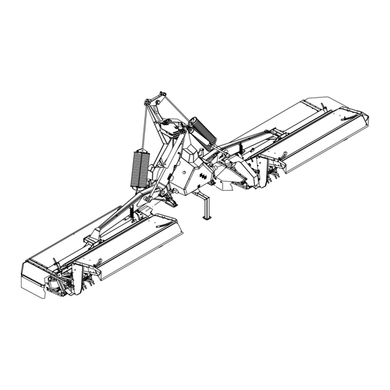
Page 20: Synopsis
About the machine Synopsis Hydraulic cylinder Springs Centre bracket Transmission Guard Deflector plates Support leg Cutterbar Rotor Hydraulic control... -
Page 21: Technical Data
About the machine Technical data Machine dimensions 3000 3400* min. 2885 4000- 4300 2600 1470* 1050 ~ 150* 2900* 2750* 2900* 9490 min. = 1700* max.= 3150* 8720 * Bx equipment is only supplied factory-fitted on basic machines. -
Page 22: Tractor Requirements
About the machine Machine specification Unit 690 T Net weight 3216 PTO (power takeoff) 1000 PTO shaft with friction clutch and freewheel Standard Power requirement kW/HK 155/210 Power requirement, including Bx equipment**, (minimum) kW/HK 162/220 Number of cutting discs parts Number of knives parts RPM, cutting discs... -
Page 23: Preparation
Preparation Preparation Preparing the The machine is divided into its main components for transport to the user. The machine must be assembled in accordance with the specific machine assembly instructions delivered with each machine. The following chapter is for initial assembling, reducing the length of the P.T.O. -
Page 24: Assembly - Attachment
Assembly - attachment Coupling a tractor and a machine together Assembly - attachment When connecting the machine and the tractor there is an increased risk of personal injury. Attention to the safety instructions assures your and others personal safety. Failure to follow the safety instructions may result in serious injuries. Therefore, when connecting the machine and the tractor you should: •... -
Page 25: Attachment Of The Tractor
Assembly - attachment Attachment of the Lock the tractor's lift arms Lock the tractor's lift arms at the correct height. tractor If the lift arms are at the correct height,it will prevent damage to the PTO shaft and injury to persons in the vicinity. Lowering or raising the lift arms can lead to injury and can damage the PTO shaft. - Page 26 Assembly - attachment > All support legs on the machine must be placed in the position Support leg shown and secured with a pin. > Reverse the tractor close to the machine and couple the tractor's lift arms to the machine as shown. Lifter...
- Page 27 Assembly - attachment Hydraulic top link The hydraulic top link can be fitted with two different joints, as different brands of tra ctor have dif ferent mea surements be tween th e lif ting points as shown on the diagram. The joints are used as follows: •...
- Page 28 Assembly - attachment > Fit the hydraulic top link as shown. Hydraulic top link > Lift the machine free of the ground and raise all support legs up to the working position. Support leg...
- Page 29 Assembly - attachment > Tighten up the tractor's stabiliser chains on both sides. Stabiliser chains > Connect the machine's electrical and hydraulic systems. »Electric connection« page 33 »Hydraulic connection« page 33, 34 Hydraulic outlet NB If the tractor ha s op en cen tre hydr aulics, an extra single-acting hydraulic outlet must be used for oil return.
- Page 30 Assembly - attachment > Activate the tractor hydraulics and pull the machine as close to the tractor as possible with the hydraulic top link. > Separate the PTO shaft and fit it as shown. NB When shor tening the P TO shaf t, refer to the manufacturer's instructions and safety directions, delivered with the PTO shaft.
- Page 31 Assembly - attachment Standard setting of the suspension Approximately 200 mm > Check the tension of the machine's springs as shown. > Tighten the springs to the dimension shown, if required. > The tension of the springs is adjusted so that a lifting weight of approximately 40 - 60 kg can raise the machine's cutting units off the ground.
-
Page 32: Hydraulic
Assembly - attachment Hydraulic Safety Only connect the hydraulics when the system is depressurised You should only connect the hydraulic hoses to the tractor's hydraulics when the hydr aulic system on both the tr actor and the machin e is depressurised. -
Page 33: Connection
Assembly - attachment Connection Electric connection Correct connection of electric control box The electrical system must be correctly connected: • The tractor power supply must be 12 V. • The tractor power supply terminals must be turned in the right direction. - Page 34 Assembly - attachment The machine is factory fitted with a hydraulic system suited to tractors with open centre hydraulics. Closed centre hydraulics If the ma chine mu st be used wit h tra ctors with closed centre and LS hydraulics hydraulics or LS hydraulics, please contact your local dealer for further information.
-
Page 35: First Start-Up Of Machine
Assembly - attachment Control valves The function of the control valves is as follows: Function Valve Centre linkage up/down Double-acting Pendulum brake for linkage Double-acting Raising/lowering right-hand cutting unit Double-acting Raising/lowering left-hand cutting unit Double-acting Bypass or oil pressure Double-acting Shifting side* right/left Double-acting Front lift device*... - Page 36 Assembly - attachment Friction clutch Bleeding Only carried out when staring for the first time The friction clutch on the rear cutting unit is bled as follows: > Use a suitable tool and remove the end of the PTO shaft with the friction clutch.
- Page 37 Assembly - attachment > Block the cutter bar by placing a wooden block between the two cutting discs. > Start the tractor and connect the tractor's PTO outlet. > Let the clutch rotate for approx. 5 seconds at the lowest speed possible.
- Page 38 Assembly - attachment The machine in its Check the surrounding area before starting to use the machine Before driving and using the machine the surrounding area should be transport position checked. This prevents persons and animals in the vicinity from being harmed. If the surrounding area is not checked, it may result in serious injuries to persons or animals.
- Page 39 Assembly - attachment > The machine's cutting units are secured with a mechanical lock on both sides as shown. Mechanical lock > Activate the tractor's hydraulic top link and pull the machine against the tractor as shown. • When the machine is pulled over the tractor, as much weight as possible is placed on the tractor's steered wheel.
-
Page 40: Transport On Public Roads
Transport on public roads Transport on public roads Safety Read the safety instructions carefully before driving on public road Before dr iving o n p ublic ro ad, yo u m ust re ad th e sa fety in structions carefully. -
Page 41: Checking The Machine
Transport on public roads Checking the Before travelling on the road the mac hine should be checked according to this check list: machine • Is the machine in the transport position? • Are the tractor's lift arms lowered so that the machine's total height is minimised as much as possible? •... -
Page 42: Operation
Operation Operation Safety Read the safety instructions before using the machine Before using the ma chine, th e ope rator shou ld re ad the safety instructions carefully. »Safety« page 5 Attention to the safety instructions assures your and others personal safety. -
Page 43: Operation
Operation Operation Safety The operator should be instructed carefully before the machine is put into use The ma chine should only b e used if the op erator h as be en g iven thorough instructions. Thorough machine instruction allows safe usage. Insufficient instructions can result in wrong usage of the machine and accidents. - Page 44 Operation Control box Electric functions Operation of the control box functions is described below. 000000 000000 79.228.100 Pos. Action Function Pressure The cutting units are shifted to the left Pressure The cutting units are centred Pressure The cutting units are shifted to the right Variable position Belt speed, left-hand side Variable position...
- Page 45 Operation Electric signals Operation of the control box functions is described below. 000000 000000 79.228.100 Pos. Indicator Function Shifting the cutting units to the left Shifting the cutting units to the right Left-hand belt in working position Right-hand belt in working position Hour counter with trip function which can be reset Hour meter - total hours All hydraulic functions are locked for transportation...
- Page 46 Operation Setting Conditioner plate Handle The distance b etween th e cond itioner pla te and th e r otor ca n be adjusted using the handle. The conditioner plate is adjusted in the following way: > Pull the handle in the direction shown. >...
- Page 47 Operation Rotor The rotor has a set speed of 900 rpm. As optional equipment, the rotor can be set to 600 RPM. The recommended rpm for the rotor should be as follows: Type of crop Rotor Pulley on the Pulley on transmission the rotor Normal, clean grass crops and crops with moderate amounts of...
- Page 48 Operation > Completely loosen the bolt on the spring. > Remove the V-belts. V-belt > Remove the bolt for the pulley. > Remove the pulley. Bolt Pulley > Remove the pulley > Fit the pulley for 600 rpm. > Fit the bolt for the pulley. Bolt Pulley...
- Page 49 Operation > Fit the V-belts V-belt > Tighten the springs until the target shown. 80 mm > Attach the PTO shaft to the bevel gear. > Fit the guard around the V belt transmission. Guard...
- Page 50 Operation Deflector plates The machine is fitted with deflector plates, making it possible to adjust the cutting swath so it can later be processed by a chopper. The cutting swath can be set in two ways: • With deflector plates fitted on the machine: The crop is collected into a compact swath.
- Page 51 Operation Suspension The springs contain a very large amount of stored energy Always proceed with the utmost care and consideration when working with the springs. The springs are loaded with very large amounts of energy which can be released very suddenly. Failure to take due care may result in serious injuries or death.
- Page 52 Operation Working in the field Check the surrounding area before starting to use the machine Before driving and using the machine the surrounding area should be checked. This prevents persons and animals in the vicinity from being harmed. If the surrounding area is not checked, it may result in serious injuries to persons or animals.
- Page 53 Operation > Press and hold the indicated switch. Joystick • The electronic lock is removed from the cutting units. > Move the joystick down. 000000 000000 • When both cutting units are lowered by approximately 45 degrees, the activation device is removed from the electronic lock. >...
- Page 54 Operation Machine start-up > Carefully connect the tractor's PTO outlet. • The indicator light in the control box comes on to indicate that the PTO shaft is rotating 000000 000000 > Carefully increase the speed of the PTO outlet to 1000 RPM. >...
- Page 55 Operation Turning at headlands Front lift device* * Optional equipment. * Only in conjunction with the front cutting unit. »Optional equipment« page 131 Turning at the headland is performed in the following way: Switch > Press the indicated switch. 000000 000000 >...
- Page 56 Operation Rear cutting unit Turning at the headland is performed in the following way: Joystick > Move the control box joystick up. > Release the joystick straight away. 000000 000000 • Both of the machine's cutting units are raised by 15 degrees and stop automatically.
- Page 57 Operation Individual operation of the cutting unit Right-hand cutting unit Joystick The right-hand cutting unit is raised in the following way: > Move the joystick to the right. 000000 000000 > Release the joystick straight away. • The right-hand cutting unit is raised by 15 degrees and stops automatically.
- Page 58 Operation Left-hand cutting unit The left-hand cutting unit is raised in the following way: Joystick > Move the joystick to the left. > Release the joystick straight away. 000000 000000 • The left-hand cutting unit is raised by 15 degrees and stops automatically.
- Page 59 Operation Shifting the position of the cutting units Only available as extra »Optional equipment« page 131 equipment Cutting unit to the right Switch The cutting units are shifted to the right in the following way: > Press and hold the indicated switch. •...
- Page 60 Operation Cutting unit to the left The cutting units are shifted to the left in the following way: Switch > Press and hold the indicated switch. • The machine now shifts to the left. 000000 000000 • The control box indicator light comes on and indicates that the machine is shifted to the left.
- Page 61 Operation Operating the Bx equipment Bx equipment is only supplied factory-fitted on basic machines Raising the right-hand belt Switch The right-hand belt is raised as follows: > Press and hold the indicated switch. • 000000 000000 The belt is raised. •...
- Page 62 Operation Raising the left-hand belt Switch The left-hand belt is raised as follows: > Press and hold the indicated switch. • The belt is raised. 000000 000000 • The indicator light on the control box goes out. > Release the switch when the belt is completely raised. 79.228.100 NB The belt stops automatically when it is raised.
- Page 63 Operation The crop is left in 3 swaths The crop is left in 3 swaths. • All 3 cutting units are operating with deflector plates. • The width of the swaths is approximately 1.4 metres. Width of the swath: approx. 1.4 metres The crop is spread The crop is spread out over the machine's entire working width.
- Page 64 Operation Using Bx belt equipment Bx equipment is only supplied factory-fitted on basic machines. »Operating the Bx equipment« page 61 The crop is left in 1 swath. • The crop from the 9 metres is collected into 1 swath using the Bx belt equipment which throws the crop in towards the centre.
-
Page 65: Cleaning
Cleaning Cleaning Before cleaning Higher risk when cleaning the equipment When cleaning, there is an increased risk of injury. Attention wh en car rying ou t clea ning wo rk pr otects yo ur own an d others safety. Failure to follow the safety instructions may result in serious injuries. Therefore, do the following before cleaning: •... -
Page 66: Cleaning
Cleaning Cleaning Use the correct cleaning agents Use only PH neutral cleaning agents when cleaning the machine. PH neutral cleaning agents give your machine maximum protection. Cleaning agents with either high or low PH value can be corrosive on plastic, rubber and varnished surfaces. •... - Page 67 Cleaning • The conditioner plate drops down onto the rotor. > Clean between the conditioner plate and the upper plate on both cutting units. After cleaning the conditioner plate, carry out the following: > Check that the handle is in the bottom position. >...
-
Page 68: After Cleaning
Cleaning > Pull the handle back to the required position. > Release the handle. > Check that the handle is securely locked. > Fit the bolt. > This procedure is carried out on both cutting units. Bolt • After cleaning Let the remaining water run off for about 1 hour. -
Page 69: Parking And Storage
Parking and Storage Parking and Storage Before storage At the end of the season, the machine should be prepared for storage: > Check and tighten all bolts. »Torque moment« page 143 > Repair any damaged components. > Replace any defective components. >... - Page 70 Parking and Storage Hydraulic Only disconnect hydraulics when system is depressurised You sh ould on ly d isconnect the h ydraulic ho ses fr om the tractor 's hydraulics if the hydraulic systems on both tractor and machine are depressurised. There is a risk that the machine will move accidentally.
- Page 71 Parking and Storage > All support legs on the machine must be placed in the position shown and secured with a pin. > Set the machine down on the surface. Support leg NB If the machine is fitted with high skids, wooden blocks 50-60 mm high must be placed under both the right and left-hand side plates on both cutting units when the machine is uncoupled.
- Page 72 Parking and Storage > Remove the P.T.O. shaft from the machine. PTO shaft > Remove the tractor's hydraulic top link from the machine. Hydraulic top link > Remove the tractor's lift arms from the machine. Lifter > Remove the machine's control box from the tractor cab. 000000 000000 79.228.100...
- Page 73 Parking and Storage Control box When the control box has been removed from the tractor cab it should be stored in a dry environment. 000000 000000 79.228.100 PTO shaft Friction clutch When the PTO shaft is removed from the machine, it must be stored in a dry environment.
-
Page 74: Storage
Parking and Storage Storage When the season is over , the machine should be readied for winter storage: Carry out the following: • Clean the machine thoroughly. »Cleaning« page 65 • Change the oil in the transmission cases. »Changing oil« page 113, 114 ... -
Page 75: Maintenance
Maintenance Maintenance For your own Comply with the service and maintenance intervals given in the instructions safety Comply with the intervals for service and maintenance as given in the instructions. By co mplying with the m aintenance inter vals yo u a ssure that th e machine will operate wit hout malfunctions and give max imum... -
Page 76: General Instructions
Maintenance General These instru ctions concern g eneral ma intenance wo rk. S pecific maintenance work proc edures for each mac hine will be des cribed instructions later. When performing all main tenance wo rk the machine must be secured in th e tr ansport po sition. - Page 77 Maintenance Maintenance inter- vals • • Hydraulic hoses, every 4 years • Cutting disc after 1 hour of use • • Cutting disc • Cutting disc after 1 hour of use • • Knives • • Universal joint • • Friction clutch •...
- Page 78 Maintenance • • Rotor • • • • • • Accumulator* • • • • Control box (fuse) • • • • Cleaning the conditioner plate *May only be carried out by authorised service personnel.
-
Page 79: Pto Shaft Check
Maintenance Safety in connection with maintenance work on the machine When w orking on th e m achine the tractor m ust b e st opped a nd secured. This prevents the PTO shaft from suddenly starting to rotate. If the tractor and the PTO shaft have not been connected following the instructions, serious accidents causing damage to limbs can occur. -
Page 80: Lubrication
Maintenance Lubrication Every day Rotor bearing The left bearing on the ro tor o n bo th cu tting un its is lub ricated as follows: > Press the nozzle on the grease gun over the grease nipples. > Pump 1, max. 2 times with the grease gun. ... - Page 81 Maintenance Lifting cylinder The lifting cylinder bearings are lubricated as follows: > Press the nozzle on the grease gun over the grease nipples. > Pump 1, max. 2 times with the grease gun. »Maintenance intervals« page 77 »Lubricants« page 143 58.237.000 Top connecting link The fr ont be arings on the top connecting links ar e lubr icated as...
- Page 82 Maintenance Bearings for the arms The top bearings on the top connecting links are lubricated as follows: > Press the nozzle on the grease gun over the grease nipples. > Pump 1, max. 2 times with the grease gun. »Maintenance intervals« page 77 ...
- Page 83 Maintenance Left-hand arm The left-hand arm for the cutting unit is lubricated as follows: > Press the nozzle on the grease gun over the grease nipple. > Pump 1, max. 2 times with the grease gun. »Maintenance intervals« page 77 ...
- Page 84 Maintenance Every 80 hours of use Spring bracket The spring bracket is lubricated as follows: > Press the nozzle on the grease gun over the grease nipples. 58.237.000 > Pump 1, max. 2 times with the grease gun. »Maintenance intervals« page 77 ...
-
Page 85: Service - Check
Maintenance Service - check Safety concerning maintenance work on the cutting unit When wo rking on the cutting un it the tractor mu st be sto pped an d secured. This prevents the machine from suddenly starting to rotate. If the tractor and the PTO shaft have not been connected following the instructions, serious accidents causing damage to limbs can occur. - Page 86 Maintenance > Check the position of the cutterb ar with a spirit level and, if needed, adjust its position with a wooden block. Spirit level > Locate the oilplug on the left-hand side of the cutterbar. > Use a suitable tool to remove it. •...
- Page 87 Maintenance Transmission Pay attention when carrying out oil change Use barrier cream or protective gloves when changing oil. It will protect your hands against skin injuries. Direct contact with the oil could lead to serious skin injuries. Use the correct oil type Always use the correct oil type for the transmission.
- Page 88 Maintenance Bevel gear Checking the oil level Every 80 hours of use The oil level is checked as follows: NB The machine must be horizontal. > Remove the dipstick. > Check that the oil level is up to the “max.” indication on the dipstick. Dipstick NB The o il le vel on the m ain gear m ust always be b etween “...
- Page 89 Maintenance Knives Safety concerning maintenance work on the cutterbar When wor king o n the cutte rbar, th e tr actor m ust be stopped an d secured. This prevents the machine from suddenly starting to rotate. If the tractor and the PTO shaft have not been connected following the instructions, serious accidents causing damage to limbs can occur.
- Page 90 Maintenance > Turn the cutting discs by hand until the knife is in the position shown. 95 Nm +/- 5 > Inspect the condition of the knives for wear. > Inspect the bolt for damage or wear. • If the bolt is damaged or worn, it must be changed. NB The minimum diameter of the bolt must not be less than 16 mm.
- Page 91 Maintenance Cutting disc Safety concerning maintenance work on the cutterbar When wor king o n the cutte rbar, th e tr actor m ust be stopped an d secured. This prevents the machine from suddenly starting to rotate. If the tractor and the PTO shaft have not been connected following the instructions, serious accidents causing damage to limbs can occur.
- Page 92 Maintenance Cones Safety concerning maintenance work on the cutterbar When working on the cu tterbar, the tr actor mu st be sto pped a nd secured. This prevents the machine from suddenly starting to rotate. If the tractor and the PTO shaft have not been connected following the instructions, serious accidents causing damage to limbs can occur.
- Page 93 Maintenance > Close the machine's guard. Internal inspection Every season > Open the machine's guard. > Use a suitable tool and remove the guard around the cutterbar's transmission. • Right-hand cutting unit: guard on the left-hand side of the cutterbar. •...
- Page 94 Maintenance > Remove the cone's top cover. Top cover > Clean the inside of the cone. > Fit the cone's top cover. > Fit the guard around the cutterbar's transmission. > Remove the top cover on the cones that are found on the opposite side of the transmission.
- Page 95 Maintenance Universal joint Safety concerning maintenance work on the cutting unit When wo rking on the cutting un it the tractor mu st be sto pped an d secured. This prevents the machine from suddenly starting to rotate. If the tractor and the PTO shaft have not been connected following the instructions, serious accidents causing damage to limbs can occur.
- Page 96 Maintenance > Remove the cone's top cover. Top cover > Inspect both universal joints for wear. Universal joint Bolts > Check for broken or loose bolts. > Replace the broken bolts. > Apply Loctite 242 to the bolts. > Fit the bolts and tighten to the torque shown. 79 Nm Loctite 242...
- Page 97 Maintenance If there are loose bolts the following procedure should be followed: Bolts > Remove and clean the bolts. > Apply Loctite 242 to the bolts. > Fit the bolts and tighten to the torque shown. > Fit the cone's top cover. >...
- Page 98 Maintenance Stone guard and counter knife Every 40 hours of use »Maintenance intervals« page 77 The stone guard and counter knife are inspected as follows: ! The machine is mo unted on the tra ctor an d place d in th e tra nsport position as follows >...
- Page 99 Maintenance > Carry out a visual inspection of the machine's stone guard and counter knife for wear. NB Stone guards and counter knives with visible holes caused by heavy wear must be replaced immediately. »Stone guard and counter knife« page 120 >...
- Page 100 Maintenance Rotor Safety concerning maintenance work on the cutting unit When wor king on the cu tting unit th e tr actor must be stopped and secured. This prevents the machine from suddenly starting to rotate. If the tractor and the PTO shaft have not been connected following the instructions, serious accidents causing damage to limbs can occur.
- Page 101 Maintenance Transmission After 10 hours of use, thereafter every 40 hours »Maintenance intervals« page 77 of use The V-belts on the rotor must be regularly checked. The V-belt for the rotor transmission is checked in the following way: > Use a tape measure or similar to measure the springs as shown. >...
- Page 102 Maintenance Friction clutch Safety concerning maintenance work on the transmission When working on the transmission the tractor must be stopped and secured. This prevents the machine from suddenly starting to rotate. If the tractor and the PTO shaft have not been connected following the instructions, serious accidents causing damage to limbs can occur.
- Page 103 Maintenance > Open the machine's guard. > Block the cutter bar by placing a wooden block between the two cutting discs. > Start the tractor and connect the tractor's PTO outlet. > Let the clutch rotate for approx. 5 seconds at the lowest speed possible.
- Page 104 Maintenance Control box fuse Disconnect the power source when working on the electrical systems Always disconnect the power source before you start working on the electric system. This will prevent short circuits and damage to the electric circuit. There is a r isk o f bu rns a nd o ther serious in juries if th e e lectrical systems short circuit.
- Page 105 Maintenance Accumulator Very high amount of accumulated pressure in the accumulator Do not attempt to take the accumulator apart. The accumulator contains very high accumulated pressure and may only be taken apart by authorised service personnel. Attempting to take the accumulator apart can lead to serious or fatal injury.
-
Page 106: Replacement
Maintenance Replacement Safety concerning maintenance work on the cutterbar When working on the cu tterbar, the tr actor mu st be sto pped a nd secured. This prevents the machine from suddenly starting to rotate. If the tractor and the PTO shaft have not been connected following the instructions, serious accidents causing damage to limbs can occur. - Page 107 Maintenance Changing oil After 10 hours of use Thereafter every 200 hours of use or once a year Right-hand cutting unit »Maintenance intervals« page 77 Joystick The oil in the cutterbar is changed as follows: > Move the joystick to the right. 000000 000000 >...
- Page 108 Maintenance > Locate the drain plug and remove it. > Let the oil flow into a suitable container. > Allow the last of the oil to drip out of the cutterbar for approx. 10 - 15 minutes. > Fit the drain plug into the cutterbar and tighten it fully. Joystick >...
- Page 109 Maintenance > Check the position of the cutterbar with a spirit level and, if needed, adjust its position with a wooden block. > Check that the cutterbar is also roughly horizontal in the direction of travel. Correct the setting of the cutterbar by adjusting the length of the top link.
- Page 110 Maintenance Left-hand cutting unit > Activate the tractor's lift arms and raise the machine as high as possible. > Position a support under the right-hand side of the cutterbar. NB It is imp ortant th at th e machin e is correctly s ecured w ith a sturdy support before work is started.
- Page 111 Maintenance > Activate the tractor lift arms, raise the machine up and remove the support. > Activate the tractor's lift arms and lower the machine down onto a flat surface. > Open the machine's guard. > Check the position of the cutterbar with a spirit level and, if needed, adjust its position with a wooden block.
- Page 112 Maintenance > Remove the oilplug for filling with oil. > Fill up with the new oil until the oil level is as shown. > Check the oil level with a measuring instrument and top it up if necessary. • Amount of oil: approximately 4.1 litres. ...
- Page 113 Maintenance Transmission Safety concerning maintenance work on the transmission When working on th e transmission the tractor must be stop ped and secured. This prevents the machine from suddenly starting to rotate. If the tractor and the PTO shaft have not been connected following the instructions, serious accidents causing damage to limbs can occur.
- Page 114 Maintenance Bevel gear Changing oil Every season »Maintenance intervals« page 77 Quantity of oil during oil change: 1 litre The oil is changed as follows: Oilplug > Use a suitable tool to remove the oilplug. > Let the oil flow into a suitable container. >...
- Page 115 Maintenance Knives Safety concerning maintenance work on the cutting unit When wo rking on the cutting un it the tractor mu st be sto pped an d secured. This prevents the machine from suddenly starting to rotate. If the tractor and the PTO shaft have not been connected following the instructions, serious accidents causing damage to limbs can occur.
- Page 116 Maintenance Cutting disc Safety concerning maintenance work on the cutting unit When wor king on the cu tting unit th e tr actor must be stopped and secured. This prevents the machine from suddenly starting to rotate. If the tractor and the PTO shaft have not been connected following the instructions, serious accidents causing damage to limbs can occur.
- Page 117 Maintenance > Fit the knife and bolt on the new cutting disc. 95 Nm +/- 5 > Tighten up the bolt with a torque wrench to the torque shown. Bolt Bolt 80 Nm +/- 5 Loctite 242 > Apply Loctite 242 or a similar product to all bolts. >...
- Page 118 Maintenance Universal joint Safety concerning maintenance work on the cutting unit When wor king on the cu tting unit th e tr actor must be stopped and secured. This prevents the machine from suddenly starting to rotate. If the tractor and the PTO shaft have not been connected following the instructions, serious accidents causing damage to limbs can occur.
- Page 119 Maintenance > Remove the cone's top cover. Top cover Bolts > Remove the bolts and replace the PTO shaft. > Clean the bolts. > Apply Loctite 242 to the bolts. > Fit the bolts and tighten to the torque shown. >...
- Page 120 Maintenance Stone guard and Safety concerning maintenance work on the cutting unit When wor king on the cu tting unit th e tr actor must be stopped and counter knife secured. This prevents the machine from suddenly starting to rotate. If the tractor and the PTO shaft have not been connected following the instructions, serious accidents causing damage to limbs can occur.
- Page 121 Maintenance > The machine's cutting units are secured with a mechanical lock on both sides as shown. Mechanical lock > Remove the worn stone guard and counter knife. > Fit the new stone guard and counter knife. NB Stone guards and counter knives with visible holes caused by heavy wear must be replaced immediately.
- Page 122 Maintenance > Make sure that there are no persons in the surrounding area. > Remove both mechanical locks from the cutting units. > Connect the tractor hydraulics. Mechanical lock > Press and hold the indicated switch. • The electronic lock is removed from the cutting units. 000000 000000 >...
- Page 123 Maintenance Rotor Safety concerning maintenance work on the cutting unit When wo rking on the cutting un it the tractor mu st be sto pped an d secured. This prevents the machine from suddenly starting to rotate. If the tractor and the PTO shaft have not been connected following the instructions, serious accidents causing damage to limbs can occur.
- Page 124 Maintenance Transmission As required »Maintenance intervals« page 77 The V-belts are replaced as follows: > Use a suitable tool to remove the guard around the V belt transmission. > Remove the PTO shaft from the bevel gear. Guard > Completely loosen the bolt on the spring. >...
- Page 125 Maintenance > Fit the V-belts V-belt > Tighten the springs until the target shown. NB On a new machine, or when fitting new V-belts, the V-belts should be checked after a few hours of use. 80 mm > Attach the PTO shaft to the bevel gear. >...
- Page 126 Maintenance Friction clutch Safety concerning maintenance work on the transmission When working on the transmission the tractor must be stopped and secured. This prevents the machine from suddenly starting to rotate. If the tractor and the PTO shaft have not been connected following the instructions, serious accidents causing damage to limbs can occur.
- Page 127 Maintenance > Remove all the bolts on the friction clutch. > Take the friction clutch apart. > Clean all surfaces in contact with the friction discs if deemed necessary. NB All contact surfaces must be clean and free from grease and oil. >...
- Page 128 Maintenance > Fit and tighten both PTO shafts on the machine. Friction clutch PTO shaft NB Take care to fit the PTO shafts correctly, as shown in the illustration. Friction clutch...
- Page 129 Maintenance Control box fuse Disconnect the power source when working on the electrical systems Always disconnect the power source before you start working on the electric system. This will prevent short circuits and damage to the electric circuit. There is a risk of bu rns a nd other serious in juries if th e e lectrical systems short circuit.
- Page 130 Maintenance Accumulator Very high amount of accumulated pressure in the accumulator Do not attempt to replace the accumulator. The accumulator contains very high accumulated pressure and may only be taken apart by authorised service personnel. Attempting to replace th e accumu lator can l ead to ser ious o r fat al injury.
-
Page 131: Optional Equipment
Optional equipment Optional equipment Spreading device Spreading device The machine ca n b e fitted with a flip- over spr eading de vice that ensures a perfect spreading of the crop. The spreading device is simple to use and can be swung round when in use. -
Page 132: Throwing Wings
Optional equipment Throwing wings Fitting throwing wings is recommended to rectify any stripe problems with crops, caused by grass blocking the cutting discs. NB The th rowing wing s a re sp ecifically ma de fo r clockwise and anti- clockwise cutting discs. -
Page 133: Pto Shaft
Optional equipment PTO shaft 6-, 20- and 21-splined universal joint The PTO shaft on the machine can be fitted with a universal joint with the following number of splines: • 6 splines. • 20 splines. • 6-, 20- or 21-splined 21 splines. -
Page 134: Oil Cooler For Bx Equipment
Optional equipment Oil cooler for Bx equipment An oil cooler can be fitted to Bx equipment, for efficient cooling of the hydraulic oil. The oil cooler is recommended when working in warm climates. NB It ca n o nly be fitt ed to a m achine s upplied fac tory-fitted with Bx equipment. -
Page 135: A-Frame
Optional equipment A-frame A category 2 A-frame can be provided as extra equipment for coupling the machine. A-frame, category 2 Front lift device equipment Front lift device Tractors with a fr ont lif t de vice ca n be fitted with e quipment fo r operating the front lift device with the control box. -
Page 136: Straw Divider
Optional equipment Straw divider The machine can be fitted with straw dividers on both the left and right- hand side of the machine. The straw divider is to be used for mowing grass seed crop as well as long matted grass. Straw divider... -
Page 137: Troubleshooting
Troubleshooting Troubleshooting Electric and hydraulic system Fault Possible cause Remedy Page Electrical system No response Check the control box fuse Check the tractor's 12 V current supply Hydraulic system The machine's hydraulic functions do Check that the hydraulic hoses are not work correctly connected to the tractor's outlet... - Page 138 Troubleshooting Fault Possible cause Remedy Page Conditioning too The distance between the conditioner Move the conditioner plate closer to weak plate and the rotor is too great the rotor The rotor's Y-fingers are worn down Replace the Y-fingers The rotor rpm is too low Increase the speed of rotation to 900 rpm.
-
Page 139: Warranty
Warranty Warranty Guidelines for The wa rranty per iod for our pr oduct is 1 2 mon ths fro m the date of purchase. The warranty does not include the parts subject to wear. warranty Warranty claims can be made with Kverneland warranty application which must be filled out by your local Kverne land dealer where your machine/equipment was purchased. -
Page 140: Disposal
Disposal When th e ma chine r eaches the e nd of it s service life it must be Disposal disposed of in the correct way. Observe the following: Metal parts Send u sable p arts to an a uthorised r ecycling station. Larger scrap parts must be taken to an authorised breaker's yard where they can be processed in accordance with current regulations. -
Page 141: Eu Declaration Of Conformity
EU declaration of conformity EU declaration of conformity EU Directive 98/37/ Kverneland Group Kerteminde AS EC and 2006/42/ Taarupstrandvej 25 DK - 5300 Kerteminde Denmark hereby declare under our sole responsibility that the following product: 690 T and ancillary equipment Applicable as from machine No: KT 415.946 which the declaration refers to complies with the fundamental safety... -
Page 142: Notes
Notes Notes... -
Page 143: Technical Information
Technical information Technical information Conversion table Basic unit: SI - unit Conversion figures: Length 39.4 in = 3.3 ft = 1.1 yd = 0.00062 miles (US) Area 1.2 yd = 10.8 ft = 0.00025 acre = 0.0001 ha Volume 1 dm (1 l) 61 in = 0.035 ft... -
Page 144: Index
Index Index Maintenance Lubrication Assembly - attachment Maintenance intervals Attachment of the tractor Replacement The machine in its transport position Service - check Working position Attachment of the tractor Notes Before the machine is connected Bevel gear Changing oil Operation Checking the oil level Electrical hydraulic controls Optional equipment... - Page 145 Index Cones Control box fuse Cutting disc Friction clutch Knives Oil, bevel gear Oil, cutterbar Oil, main gear Stone guard and counter knife Universal joint Y-fingers Setting Conditioner plate Deflector plate Rotor Suspension Spare parts Standard setting of the suspension Storage Control box PTO shaft...
Need help?
Do you have a question about the EXTRA 690 T and is the answer not in the manual?
Questions and answers