
Related Manuals for Vicon EXTRA 632 T


Summary of Contents for Vicon EXTRA 632 T
- Page 1 EXTR∆ 632 T Operator's Manual Translation of the original operator’s manual Date of publication 12/2009 Date printed 12/2009 Language Valid as from serial No.: 403.218 Reference No: 90000502EN Index 119-12...
- Page 2 Identification of machine So that your dealer can help you as quickly as possible, he needs to have some information about your ma- chine. Enter your information here. EXTR∆ 632 T Description Working width 3.2 m Weight 1200 kg Machine number Accessories Dealer address...
-
Page 3: Table Of Contents
Contents Contents Contents ............4 Replacement Instruction manual target group Extra equipment..........89 The meaning of the symbols Lighting kit Safety ..............5 Hydraulic device for the deflector plate For your own safety Skids Who can operate the machine? Chain for locking the lift arms Connecting Throwing wings Load capacity... -
Page 4: Contents
Contents Contents Instruction man- This instruction manual is intended for trained farmers and others who are qualified to work in agriculture and who are familiar with assem- ual target group bling equipment. For your own safety Read this instruction manual thoroughly before use and mounting. By doing this you have optimal working conditions and you can work in safety. -
Page 5: For Your Own Safety
Safety Safety For your own This chapter includes general safety instructions. Furthermore, each chapter in the instruction manual includes specific safety instructions safety that are not described here. The safety instructions must be complied with • In terms of your own safety. •... - Page 6 Safety Safety symbols On the machine you will find labels that serve your safety. These la- bels must not be removed. If the labels become illegible or fall off, you can order some new labels and affix them to the relevant areas. STOP...
- Page 7 Safety The meaning of the sym- bols Stop the tractor before working on the machine Be attentive! The tractor engine must ALWAYS be stopped and the ig- nition key removed before carrying out repairs, cleaning, lubricating or maintaining the machine. Read and observe the instruction manual Be attentive! Read and understand the instruction manual before the machine is put into service.
- Page 8 Safety Standing between the tractor and the tool can be dangerous There is a high risk of becoming trapped if you get in between the trac- tor and the tool. During connection and disconnection of the tool, peo- ple should always remain outside of the hazard area, and the tractor's handbrake should always be applied.
-
Page 9: Who Can Operate The Machine
Safety Who can operate Operators of this machine should only be educated farmers and per- sons who in other ways are qualified to perform agricultural work and the machine? who have knowledge on installing the equipment. Untrained or unauthorised members of staff may not use this machine. Connecting Correct attachment of the machine Coupling must be carried out in the proper manner according to the... -
Page 10: Load Capacity
Safety Only connect hydraulics when system is without pressure You should only connect the hydraulic hoses to the tractor's hydraulics when the hydraulic system on both tractor and machine is depressu- rised. There is a risk that the machine will move unintentionally. Unintentional movement of the machine may result in serious injuries. -
Page 11: Transport On Public Roads
Safety Transport on pub- Control that the machine meets the Road Traffic Act's require- ments concerning its condition. lic roads When driving on public roads, the machine must live up to the Road Traffic Act's current requirements. This ensures traffic safety both for you and other road users. Not meeting the requirements can result in accidents. -
Page 12: Use
Safety The operator should be instructed carefully before the machine is put into use Only use the machine when the operator has been given thorough in- structions. Thorough machine instruction results in safe usage. 95-002-1 fr Insufficient instructions can result in wrong usage of the machine and accidents. - Page 13 Safety Check the surrounding area before taking machine into use Before driving and using the machine the surrounding area should be checked. This prevents persons and animals around the machine from being exposed to danger. If the surrounding area is not checked, it may result in serious injuries to persons or animals.
-
Page 14: Disconnection
Safety Disconnection Heightened risk of personal injury when disengaging There is an increased risk of personal injury when disengaging the machine from the tractor. Attention to the above instruction points will protect you and others 95-038 fr from injury. Failure to follow the above instructions may result in serious injuries. Therefore, when disconnecting: •... -
Page 15: Maintenance
Safety Maintenance Comply with the service and maintenance intervals given in the instructions Comply with the intervals for service and maintenance as given in the instructions. By complying with the maintenance intervals you assure that the ma- chine will operate without malfunctions and give maximum protection to the surroundings. - Page 16 Safety Be careful when cleaning with high pressure cleaner Only clean bearings, hydraulic hoses, plastic components, electrical control boxes and electrical equipment with low water pressure. By cleaning with low water pressure you will protect sensitive equip- ment on the machine. Cleaning with high water pressure could damage vital parts of the ma- chine.
-
Page 17: Further Safety Instructions
Safety Further safety in- Follow the instructions when working on the machine The machine safety instructions should always be complied with. structions It will protect you and others from personal injury. Failure to follow the safety instructions may result in serious injuries. Apart from the safety instructions the following should be complied with: 95-005 fr... -
Page 18: About The Machine
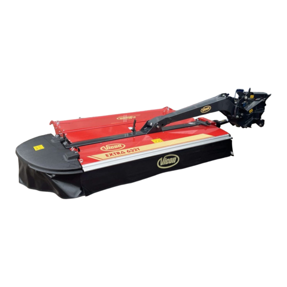
About the machine This chapter includes general information about your machine. Fur- About the machine thermore, following information are included: • The machine application area. • The machine characteristics. • View of the machine. • Technical data. The field of appli- 632 T is a swather intended to lay common grass and cereal crops in swathes. -
Page 19: Synopsis
About the machine Synopsis Hydraulic cylinder Suspension Guard Compartment for extra knives Hydraulic cylinder P.T.O. shaft Spreading device Cutterbar... -
Page 20: Technical Data
About the machine Technical data Machine dimensions All measurements are given in mm. -
Page 21: Tractor Requirements
About the machine Machine specifica- tion Unit 632 T Net weight 1200 P.T.O. Power take off 1000 Power requirement, minimum kW/HK 65 / 90 Number of cutting discs Number of knives RPM, cutting discs 3000 RPM, rotors* 600 / 940 Stubble height 35 - 50 Cutting width... -
Page 22: Preparation
Preparation Preparation Preparing the ma- For transporting the user the machine is divided into main compo- nents. The machine is assembled according to the specific assembly chine instructions delivered with each machine. The following chapter is for initial assembling, reducing the length of the P.T.O. - Page 23 Preparation Adjusting the linkage pins Category II linkage pin The machine is fitted with 2 types of linkage pin: • Category II linkage pin. • Category III linkage pin. The linkage pins are factory-fitted as shown. Category III linkage pin To change the setting of the linkage pins, perform the following: >...
-
Page 24: Assembly - Attachment
Assembly - attachment Coupling a tractor and a machine together Assembly - attachment There is an increased risk of personal injury when coupling the ma- chine and the tractor. Attention will assure yours and others safety. Failure to follow the safety instructions may result in serious injuries. Therefore, when connecting the machine and the tractor you should: •... -
Page 25: Attachment Of The Tractor
Assembly - attachment Attachment of the Lock the tractor's lift arms Lock the tractor's lift arms at the correct height. tractor Having the lifting device at the correct height prevents damage to the P.T.O shaft and injury to persons in the vicinity. Lowering or raising the lifting device can lead to personal injury and can damage the P.T.O shaft. - Page 26 Assembly - attachment > Mount the machine onto the tractor's lift arms. > Raise the machine clear of the ground. > Check that the tractor lift arms are at the same height. • Parking stand If not, lower the machine down to the ground and adjust the tractor lift arms.
- Page 27 Assembly - attachment Attaching the machine When attaching the machine there is an increased risk of personal in- jury. Attention will assure yours and others safety. Failure to follow the safety instructions may result in serious injuries. Therefore, when connecting the machine you should be sure that: •...
- Page 28 Assembly - attachment Adjusting the suspen- sion It is important that the suspension of the machine is in the correct height above the ground. It is set to the correct height in the following way: > Activate the tractor's hydraulics. >...
-
Page 29: Hydraulic
Assembly - attachment Hydraulic Safety Only connect hydraulics when the system is not pressurised You should only connect the hydraulic hoses to the tractor's hydraulics when the hydraulic system on both tractor and machine is depressu- rised. There is a risk that the machine will move unintentionally. Unintentional movement of the machine may result in serious injuries. - Page 30 Assembly - attachment Hydraulic connection Red marking The tractor must be fitted with 1 set of double-acting outlets and a sin- gle-acting hydraulic outlet, which are connected as follows: Blue marking Hydraulic outlets on Function Colour marking of the tractor the hydraulic hoses Double-acting hydrau- Machine in transport and working position...
-
Page 31: First Start-Up Of Machine
Assembly - attachment First start-up of The initial test drive of the machine is important When the machine is connected to the tractor for the first time it must machine be test driven. Attention will assure yours and others safety. Failure to follow the safety instructions may result in serious injuries. - Page 32 Assembly - attachment Adjusting the cutting After fitting the machine on the tractor, the cutting unit must be set for unit when it is lifted when turning on the headland. Bolt ! This adjustment must be carried out when the machine is first fitted to Pos.
-
Page 33: Machine In Transport Position
Assembly - attachment Machine in trans- Check the surrounding area before taking machine into use Before driving and using the machine the surrounding area should be port position checked. This prevents persons and animals around the machine from being exposed to danger. If the surrounding area is not checked, it may result in serious injuries to persons or animals. - Page 34 Assembly - attachment > Activate the tractor hydraulics and swing the machine's cutting unit up to the transport position. • It is recommended that the tractor lift arms are fitted with shock ab- sorbing dampers during transport, see the instruction manual for the tractor.
- Page 35 Assembly - attachment Adjusting the trans- The transport lock ensures that the machine remains locked in the port lock transport position when being transported when the tractor's hydraulic system is in neutral. The machine's transport lock is adjusted in the following way: >...
-
Page 36: Transport On Public Roads
Transport on public roads Transport on public roads Safety Read the safety instructions carefully before driving on public road Before driving on public road, you must read the safety instructions carefully. This assures that you avoid dangerous situations and accidents. Lack of information can lead to an accident. -
Page 37: Operation
Operation Operation Safety Read the safety instructions before using the machine Before using and loading the machine the operator should read the safety instructions carefully. → »Safety« Page 5. Attention will assure yours and others safety. Failure to follow the instructions may result in serious injuries. Work on the machine should only be carried out by persons who have been thoroughly instructed The machine should only be operated when the operator has been... -
Page 38: Operation
Operation Operation Safety The operator should be instructed carefully before the machine is put into use Only use the machine when the operator has been given thorough in- structions. Thorough machine instruction results in safe usage. Insufficient instructions can result in wrong usage of the machine and accidents. -
Page 39: Before Operating
Operation Before operating Make sure that the initial start of the machine is unhindered Be aware of the area around the machine before start up. Paying attention to the area around the machine will prevent injuring persons or animals. Insufficient attention to the area around the machine can result in se- rious injuries. - Page 40 Operation Setting Conditioner plate Pos. II Pos. III Pos. I The distance between the conditioner plate and the rotor can be ad- justed using the handle. The conditioner plate is adjusted in the following way: > Pull out the lock. >...
- Page 41 Operation Rotor There is a risk that the protection may drop and harm someone The protection must be secured so that it cannot drop and harm per- sons in the vicinity of the machine. The protection can accidentally drop and harm persons in the vicinity of the machine.
- Page 42 Operation > Take the bolts previously removed and fit them as shown to both sides of the machine. > Check that the protection is secured so that it cannot drop. ! This ensures that the protection is secured so that it will not drop and strike anyone during maintenance, cleaning or servicing work on the rotor.
- Page 43 Operation Deflector plates The machine is fitted with 2 deflector plates, making it possible to ad- just the swath width for the following collection with chopper. The cutting swath should be as broad and even as possible. The deflector plates are equipped with adjustable plates as shown. >...
- Page 44 Operation Spreading device The machine is fitted with a spreading device, that can set the spread direction as required. The spreading device is fitted with two handles which should be used when adjusting the spread. The direction of the spread is adjusted in the following way: >...
- Page 45 Operation Ground pressure Valve Manometer The ground pressure is set in the following way: > Open the valve shown. Valve open > Activate the tractor's hydraulics and raise the machine's cutting unit until the manometer shows 140-150 bar. Valve closed Manometer >...
- Page 46 Operation > Activate the tractor hydraulics and lower the cutting unit of the ma- chine > Continue to activate the tractor's hydraulic system. ! The tractor's hydraulic system must be in the floating position or the MPORTANT lowering position. Valve >...
- Page 47 Operation Working in the field Check the surrounding area before taking machine into use Before driving and using the machine the surrounding area should be checked. This prevents persons and animals around the machine from being exposed to danger. If the surrounding area is not checked, it may result in serious injuries to persons or animals.
-
Page 48: Before Cleaning
Cleaning Cleaning Before cleaning Higher risk when cleaning the equipment When cleaning, there is a higher risk of personal injury. Attention when carrying out cleaning work protects your own and oth- ers safety. Failure to follow the safety instructions may result in serious injuries. Therefore, do the following before cleaning: •... -
Page 49: Cleaning
Cleaning Cleaning Use the proper cleaning agents Use only PH neutral cleaning agents when cleaning the machine. PH neutral cleaning agents give your machine a maximum protection. Cleaning agents with either high or low PH value can be corrosive on plastic, rubber and painted surfaces. -
Page 50: Parking And Storage
Parking and Storage Parking and Storage Before storage When the season has come to an end the machine should be pre- pared for storage: > Check and tighten all bolts. → »Torque moment« Page 97. > Repair all damaged components. >... - Page 51 Parking and Storage > Check that the machine is in the working position. Parking stand > Turn the parking stands out as shown. Parking stand > Turn the parking stand out as shown. > Fold the parking stand up as shown. >...
-
Page 52: Storage
Parking and Storage Storage When the season is over, the machine should be readied for winter storage: Carry out the following: • Clean the machine thoroughly. → »Cleaning« Page 48. • Change the oil in the transmission case. → »Lubricants« Page 97. •... -
Page 53: Maintenance
Maintenance Maintenance For your own Comply with the service and maintenance intervals given in the instructions safety Comply with the intervals for service and maintenance as given in the instructions. By complying with the maintenance intervals you assure that the ma- chine will operate without malfunctions and give maximum protection to the surroundings. -
Page 54: General Instructions
Maintenance General instruc- These instructions concern general maintenance work. Specific main- tenance work procedures for each machine will be described later. tions When performing all maintenance work the machine must be secured in the transport position. If the working position is necessary for per- forming maintenance work, you will find appropriate instructions con- cerning this work. - Page 55 Maintenance Maintenance inter- vals • Hydraulic hoses every 4 years • • Bearing/Universal joint • • • Cutting disc • • • • • • • • Knives • • • • • • • Cones • • • • Conditioner •...
-
Page 56: P.t.o. Shaft Check
Maintenance Safety in connection with maintenance work on the machine When working on the machine the tractor must be stopped and se- cured. This prevents the PTO shaft from suddenly starting to rotate. If the tractor and the PTO shaft have not been connected according to the instructions serious accidents resulting in torn off limbs can occur. -
Page 57: Lubrication
Maintenance Lubrication Every day P.T.O. shaft > Press the nozzle on the grease gun over the grease nipple. 58.237.000 > Pump 1, max. 2 times with the grease gun. → »Maintenance intervals« Page 55. → »Lubricants« Page 97. > Press the nozzle on the grease gun over the grease nipple. >... - Page 58 Maintenance > Turn the cone until the grease nipple is visible in the hole shown. > Press the nozzle on the grease gun over the grease nipple. 58.237.000 > Pump 1, max. 2 times with the grease gun. > Remove the grease gun from the grease nipple. →...
- Page 59 Maintenance Cutterbar Be aware, when using oil Use protective cream or protective gloves when handling oil. It will protect your hands against skin injuries. Direct contact with the oil could lead to serious skin injuries. Use the correct oil type Always use the correct oil type for the transmission.
- Page 60 Maintenance > Check that the cutterbar is roughly horizontal both longitudinally and in the direction of travel. Correct the cutterbar's position by ad- justing the top link on the machine. > Locate the oilplug on the cutterbar and remove it. •...
-
Page 61: Cutterbar
Maintenance Changing oil Correct support of the machine is necessary to prevent injury The machine must be properly supported when work is being carried out underneath it. If the machine is not correctly supported, there is a high risk that it may overturn, causing injury. - Page 62 Maintenance > Remove the ring nut shown Ring nut > Open the machine's first protection. > Check that the cutterbar is roughly horizontal both longitudinally and in the direction of travel. Correct the cutterbar's position by ad- justing the top link on the machine. >...
- Page 63 Maintenance > Close the guard around the machine's cutterbar. > Fit the ring nut and fasten it. > Bleed the handbrake. Ring nut...
-
Page 64: Bevel Gear
Maintenance Gearbox Pay attention when performing oil change Use protective cream or protection gloves when changing oil. It will protect your hands against skin injuries. Direct contact with the oil could lead to serious skin injuries. Use the correct oil type Always use the correct oil type for the transmission. -
Page 65: 2-Speed Transmission
Maintenance 2-speed transmission Checking the oil level The oil level is checked as follows: → »Maintenance intervals« Page 55. > Remove oilplug 4. > Check that the oil is filled all the way up to the hole. > When topping up, remove oilplug 3. >... - Page 66 Maintenance Changing oil Correct support of the machine is necessary to prevent injury The machine must be properly supported when work is being carried out underneath it. If the machine is not correctly supported, there is a high risk that it may overturn, causing injury.
-
Page 67: Service - Check
Maintenance Service - check Knives Check the machine knives on a regular basis The machine's knives must be regularly inspected. Worn or damaged knives can unbalance the rotating parts. Vibrations can cause damage on the machine. The knives are checked in the following way: Ring nut →... - Page 68 Maintenance > Close the guard around the machine's cutterbar. > Fit the ring nut and fasten it. Ring nut...
-
Page 69: Cutting Disc
Maintenance Cutting disc The cutting discs are checked as follows: → »Maintenance intervals« Page 55. Ring nut > Remove the ring nut shown. > Open the machine's first protection. > Undertake an inspection of the state of the cutting discs for defor- mation and cracks. -
Page 70: Cones
Maintenance Cones Check the machine cones on a regular basis The machine's cones must be checked and cleaned regularly. Build up of plant waste can cause imbalance in the rotating parts. Vibrations can cause damage on the machine. External inspection An external check of the cones is carried out in the following way: →... - Page 71 Maintenance > Close the guard around the machine's cutterbar. > Fit the ring nut and fasten it. Ring nut Internal inspection An internal check of the cones is carried out in the following way: → »Maintenance intervals« Page 55. Ring nut >...
- Page 72 Maintenance > Use a suitable tool and remove the protection on the left-hand side and the top covers of the cones on both sides. > Carry out an internal inspection of the cones on the right and left- hand side for dirt. >...
- Page 73 Maintenance Universal joint The universal joint between the transmission and the cutterbar is checked in the following way: → »Maintenance intervals« Page 55. Ring nut > Remove the ring nut shown. > Open the machine's first protection. > Undertake an inspection of the state of the cutting discs for defor- mation and cracks.
- Page 74 Maintenance If there are loose bolts the following procedure should be followed: > Remove and clean the bolts. > Apply Loctite 242 to the bolts. > Mount and tighten up the bolts. → »Torque moment« Page 97. > Fit the cone cover and fasten it. >...
-
Page 75: Conditioner
Maintenance Y-fingers There is a risk that the protection may drop and harm someone The protection must be secured so that it cannot drop and harm per- sons in the vicinity of the machine. The protection can accidentally drop and harm persons in the vicinity of the machine. - Page 76 Maintenance Left-hand side > Take the bolts previously removed and fit them as shown to both sides of the machine. > Check that the protection is secured so that it cannot drop. ! This ensures that the protection is secured so that it will not drop and strike anyone during maintenance, cleaning or servicing work on the rotor.
- Page 77 Maintenance > Remove the bolts shown on both sides of the machine. Left-hand side Right-hand side > Carefully lower the rear protection of the machine down as shown. ! Be careful of the weight of the rear protection when it lowers down into position.
- Page 78 Maintenance > Fit the bolts shown on both sides of the machine. Left-hand side Right-hand side...
-
Page 79: Friction Clutch
Maintenance Friction clutch Only to be carried out af- ter prolonged standstill Bleeding of the friction clutch is carried out in the following way: → »Maintenance intervals« Page 55. > Remove the end of the P.T.O. shaft with the friction clutch. >... -
Page 80: Replacement
Maintenance Replacement Safety concerning maintenance work with the transmission When working on the transmission the tractor must be stopped and secured. This prevents the machine from suddenly starting to rotate. If the tractor and the PTO shaft have not been connected according to the instructions serious accidents resulting in torn off limbs can occur. - Page 81 Maintenance > Close the guard around the machine's cutterbar. > Fit the ring nut and fasten it. Ring nut Cutting disc The cutting discs are replaced in the following way: → »Maintenance intervals« Page 55. Ring nut > Remove the ring nut shown. >...
- Page 82 Maintenance > Mount the cutting disc on the cutterbar. Bolt > Tighten up the bolt with a torque wrench to the torque shown. 80 Nm +/- 5 Loctite 242 > Close the guard around the machine's cutterbar. > Fit the ring nut and fasten it. Ring nut...
- Page 83 Maintenance Universal joint The universal joint is replaced as shown here: → »Maintenance intervals« Page 55. Ring nut > Remove the ring nut shown. > Open the machine's first protection. > Use a suitable wrench and remove the cone cover. >...
- Page 84 Maintenance Y-fingers There is a risk that the protection may drop and harm someone The protection must be secured so that it cannot drop and harm per- sons in the vicinity of the machine. The protection can accidentally drop and harm persons in the vicinity of the machine.
- Page 85 Maintenance > Take the bolts previously removed and fit them as shown to both Left-hand side sides of the machine. > Check that the protection is secured so that it cannot drop. ! This ensures that the protection is secured so that it will not drop and strike anyone during maintenance, cleaning or servicing work on the rotor.
- Page 86 Maintenance Left-hand side > Remove the bolts shown on both sides of the machine. Right-hand side > Carefully lower the rear protection of the machine down as shown. ! Be careful of the weight of the rear protection when it lowers down into position.
- Page 87 Maintenance > Fit the bolts shown on both sides of the machine. Left-hand side Right-hand side...
-
Page 88: Friction Disc
Maintenance Friction clutch When the friction clutches' torque is felt to be too low, the friction disc should be replaced. The friction discs are replaced in the following way: → »Maintenance intervals« Page 55. > Remove the P.T.O. shaft from the machine. >... -
Page 89: Extra Equipment
Extra equipment Extra equipment Lighting kit The machine can be fitted with a lighting kit together with a reflex set. Hydraulic device for the deflector plate The machine can be fitted with a hydraulic device for operating the machine's left-hand deflector plate, so that the crop can be directed away from the edge of the unmown crop. -
Page 90: Chain For Locking The Lift Arms
Extra equipment Chain for locking the lift arms A chain is available as extra equipment to prevent the tractor's lift arms from lowering. The chain is fitted between the highest point on the tractor and one of the lift arms. Throwing wings Fitting throwing wings is recommended to rectify any stripe problems with spring crops, caused by grass blocking the cutting discs. -
Page 91: Troubleshooting
Troubleshooting Troubleshooting Hydraulic system Fault Possible cause Remedy Page The machine hangs There is too much downward pressure Adjust the ground pressure directly to the rear from the cutterbar during mowing Hydraulic The machine's hydraulic functions do Check that the hydraulic hoses are not work correctly connected to the tractor's outlet... - Page 92 Troubleshooting Fault Possible cause Remedy Page Stripes in the stub- The cutterbar does not have an ideal Adjust the angle for the cutterbar angle for a particular crop Increase speed Build up of crops on the cutting discs Increase speed Set the rotor's RPM to 940 Fit throwing wings Stubble too high...
-
Page 93: Guidelines For Guarantee
Guarantee Guarantee Guidelines for The guarantee period for our product is 12 months from the date of purchase. The guarantee does not include the wearing parts. guarantee Guarantee claims can be made with Kverneland guarantee applica- tion which must be filled out by your local Kverneland dealer where your machine/equipment was purchased. -
Page 94: Disposal
Disposal Disposal When the machine is worn out, it must be correctly disposed of, ob- serving the following: Metal parts Deliver usable parts to an authorised recycling plant. The larger scrap parts must be taken to an authorised breaker's yard where they can be processed in accordance with current regulations. -
Page 95: Eu Declaration Of Conformity
EU declaration of conformity EU declaration of conformity The EU Directive. Kverneland Group Kerteminde AS 98/37/EG and 2006/ Taarupstrandvej 25 42/EC* DK - 5300 Kerteminde Denmark declare that we alone are responsible that the product: CE plate and type plate EXTR∆... - Page 96 Notes Notes...
- Page 97 Technical information Technical information Conversion table Basic unit: SI - unit Conversion figures: Length 39.4 in = 3.3 ft = 1.1 yrd = 0.00062 miles (US) Area 1.2 yd = 10.8 ft = 0.00025 acre = 0.0001 ha Volume 1 dm (1 l) 61 in = 0.035 ft...
- Page 98 Index Index Accumulator P.T.O. Parking /disconnection of the machine. Preparing the machine Before the machine is connected Replacement Accumulator Cleaning Cutting disc Conversion table Friction clutch Crane lifting Knives Universal joint Y-fingers Disposal Electronic parts Hydraulic oil Service - check Metal parts Accumulator Plastic...
Need help?
Do you have a question about the EXTRA 632 T and is the answer not in the manual?
Questions and answers