
Related Manuals for RME Audio M-32 AD Pro II-D


Summary of Contents for RME Audio M-32 AD Pro II-D
- Page 1 High-end Converter M-32 AD Pro II-D 32-Channel 192 kHz A/D Converter DANTE | MADI with MADI & Dante User’s Guide...
- Page 2 RME M-32 AD Pro II-D User’s Guide...
-
Page 3: Table Of Contents
Table of Contents 1. Safety Precautions ............... ... - Page 4 8.3.2. Unlocking the Device ............ ...
-
Page 5: Safety Precautions
RME M-32 AD Pro II-D User’s Guide WARNING DO NOT OPEN DEVICE - RISK OF ELECTRIC SHOCK The unit has non-isolated live parts inside. No user serviceable parts inside. Refer service to qualified service personnel. WARNING MAGNETIC FIELD The device uses magnets that can be harmful to pacemaker wearers. -
Page 6: Introduction
By integrating Audinate’s Dante® IP Core on a custom built RME FPGA platform, RME is not only delivering a highly flexible solution but also gets one step closer to achieving a truly universal Audio Networking experience. Any signal reaching the M-32 AD Pro II-D can be routed and streamed over IP networks, including MADI signals! The coaxial MADI port and a slot for a second, independent or redundant optical MADI port (SFP module) can be used for daisy chaining, merging and converting MADI signals with lowest latencies. -
Page 7: Firmware Update
The unit retains all settings, including presets, when the firmware is upgraded. 2.2. Use of the Display and Encoder The M-32 AD Pro II-D can be controlled directly at the unit. For this purpose, a display and an encoder provide access to all features. -
Page 8: Tabs
RME M-32 AD Pro II-D User’s Guide To access the INPUT section: 1. Rotate the encoder to highlight the "STATE" section 2. Rotate the encoder to highlight the "INPUT" section 3. Push the encoder to open the "INPUT" section. 2.2.2. Tabs The STATE, INPUT and OUTPUT sections are further divided into tabs, which are shown when the section is opened. -
Page 9: Hardware
RME M-32 AD Pro II-D User’s Guide 3. Hardware Section 3.4, “Standby Switch” Section 3.6, “Channel Labels with Integrated Metering” Section 3.9, “Control Section” Section 3.17, “Word Clock” Section 3.16, “MIDI Connector” Section 3.14, “MADI Coaxial and SFP” Section 3.11, “Analog Line Input Connectors”... -
Page 10: Hardware Specifications
3.3. Power On The M-32 AD Pro II-D has a power off switch at the rear and a standby switch at the front. Perform the following steps to power on the M-32 AD Pro II-D: 1. Ensure either or both power inlets are properly connected to a power source. -
Page 11: Standby Switch
RME M-32 AD Pro II-D User’s Guide 3.4. Standby Switch The standby switch is used to power off the device when it is not in use. While in standby mode, the device is completely powered down except for a red ring illumination. No signals are processed or passed on. -
Page 12: Channel Labels With Integrated Metering
The use of customized channel labels helps in recurring and permanent installations. They inform the user where the analog connections terminate. The M-32 AD Pro II-D features 32 fields on the front panel, one for each analog input. Integrated backlight in shades of green, yellow, and red represents the current level for each channel. -
Page 13: Control Section
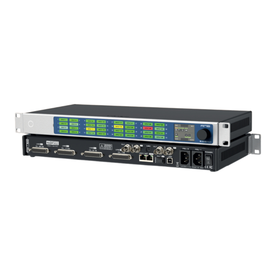
3.10. Power Supplies The M-32 AD Pro II-D has two internal power supplies (PSUs) that are connected via IEC C14 inlets labeled "PSU 1" and "PSU 2" at the rear of the device. The power supplies are designed with a wide-input voltage range, accommodating a variety of power sources. -
Page 14: Analog Line Input Connectors
3.11. Analog Line Input Connectors The rear of the M-32 AD Pro II-D features four 25-pin D-sub connectors labeled "LINE IN" with Tascam®- pinout. These analog inputs are servo-balanced, allowing balanced and unbalanced signals to be connected without a difference in level. -
Page 15: Ad Converter Specifications
• Channel separation: > 110 dB 3.14. MADI Coaxial and SFP The rear of the M-32 AD Pro II-D features coaxial and SFP MADI (AES10-2003) I/O. Each input receives up to 64 audio channels. Auto Input (see Section 9.2.2, “Connecting Two Identical MADI Signals for Redundancy”) can be activated to treat both inputs as one. -
Page 16: Network Connection
CLOCK section. 3.15. Network Connection On the rear of the M-32 AD Pro II-D, two RJ45 connectors labeled NET (PRI) and NET (SEC) provide ethernet connectivity. The supported link speeds are 1 Gb/s and 100 Mb/s. A green LED (left, LINK) signals a successful link. A yellow LED (right, ACT) signals network traffic (blinking). -
Page 17: Combine Ethernet Ports
Dante Redundancy. If both ports are connected to the same network, for example to create a daisy-chain of several M-32 AD Pro II-D devices, then the setting must be changed to Switched. In the default mode, the device is configured so that each port connects to one of two separate networks (Redundancy). -
Page 18: Usb 2.0 Type B Jack
3.18. USB 2.0 Type B Jack The USB jack at the rear of the M-32 AD Pro II-D provides an alternative connection method for web remote control when a network connection is not available. -
Page 19: Mounting The Rack Adapter Brackets
RME M-32 AD Pro II-D User’s Guide The USB port cannot be used to stream audio signals. 3.19. Mounting the Rack Adapter Brackets When the device should be mounted in a 19" rack, the rack adapter brackets must be mounted first. -
Page 20: Accessories
RME M-32 AD Pro II-D User’s Guide 4. Accessories RME offers several optional components for the M-32 AD Pro II-D: Part Number Description Analog breakout cables AI25-8XPro3 Analog breakout cable 25-pin D-sub to 8 x XLR female, 3 m (9.9 ft) AI25-8XPro5 Analog breakout cable 25-pin D-sub to 8 x XLR female, 5 m (16.4 ft) -
Page 21: Dante Connectivity
Dante controller. When the M-32 AD Pro II-D is leader, it can either use its internal clock oscillator as a reference, or one of the incoming MADI or word clock signals. -
Page 22: Changing The Device Name
To use device identification with the web remote: 1. Open the M-32 AD Pro II-D web remote in a browser (see Section 8.5.1, “Finding the Device on a Network”) 2. Press the identify icon. The icon will start rotating and the front panel level meters of the controlled device will show an animation. -
Page 23: Quick Start (Dante)
RME M-32 AD Pro II-D User’s Guide 6. Quick Start (Dante) Follow this procedure to get running quickly! 1. Load Preset 16 (Factory settings) from the STATE section 2. In the CLOCK section, choose a sample rate and verify that Dante is chosen as the current clock source. - Page 24 RME M-32 AD Pro II-D User’s Guide Further relevant information: State • Section 8.1.1, “Notification of Single Power Failure” • Section 8.2.2, “Loading Presets” • Section 8.3.1, “Locking the Device” • Section 8.4.1, “Dark Mode” • Section 8.5.2, “Web Remote”...
-
Page 25: Warranty And Support
The distributor does not accept claims for damages of any kind, especially consequential damage. Liability is limited to the value of the M-32 AD Pro II-D. The general terms of business drawn up by the distributor apply at all times. -
Page 26: Support Contacts
RME M-32 AD Pro II-D User’s Guide 7.3. Support Contacts Additionally, the following global service centers can provide support assistance: Europe Audio AG, Germany support@rme-audio.de Synthax U.K. info@synthax.co.uk Asia/Australia RME Trading Ltd., Hong Kong support@rme-trading.hk Americas Synthax Inc., U.S.A. tech.support@synthax.com Global support@rme-audio.de... -
Page 27: State Section
RME M-32 AD Pro II-D User’s Guide 8. STATE Section The STATE section contains states and settings that are unrelated to audio I/O and clock. It can be used to configure power supply warnings, presets, dark mode, level meters, and remote control. -
Page 28: Presets
Any change in the device configuration is persistent. After a power loss, the device will revert back to its last state. Additionally, the M-32 AD Pro II-D can save fifteen states in presets numbered 1-15. After a preset is loaded, any change in the configuration will result in an unsaved changes state. -
Page 29: Loading Presets
3. Press the Save button 8.2.2. Loading Presets Up to 15 custom presets can be loaded from the internal storage of the M-32 AD Pro II-D. Loading a preset cannot be undone. Ensure that any important configuration has been ... -
Page 30: Loading Factory Default Settings
STATE section. 8.3. Device Lock The M-32 AD Pro II-D can be secured against both accidental and intentional changes to its configuration. Locking the device, with or without code, protects against changes on the device itself. -
Page 31: Unlocking The Device
8.4. Front Panel Illumination The M-32 AD Pro II-D features a unique concept for its front panel illumination, which consists of: • A ring illumination around the standby switch that shows the overall state of the device. • 32 channel labels with integrated backlight metering (peak or RMS). - Page 32 RME M-32 AD Pro II-D User’s Guide To turn off illumination on the device: 1. Open the visual feedback tab in the STATE section. 2. Change any of the following: a. Power to Off to turn off the standby switch ring illumination.
-
Page 33: Changing The Meters To Peak Or Rms Mode
RME M-32 AD Pro II-D User’s Guide State of Visual Feedback Front Panel Dark Mode Global Metering Options Peak/Over Hold Reset 2. Use the corresponding toggle switches on the web remote to switch off device lighting. 8.4.2. Changing the Meters to Peak or RMS Mode Depending on the application, instantaneous peak level metering or a slower, averaged RMS metering may be preferred. -
Page 34: Signals
RME M-32 AD Pro II-D User’s Guide 2. Change OVR Hold to either: ◦ 5s to notify for five seconds ◦ On to notify until manually reset ◦ Off to deactivate over notifications. To reset infinite full scale notifications: 1. Open the visual feedback tab in the STATE section. -
Page 35: Remote Control Overview
When opening the ports, larger levelmeters are shown with precise levels. 8.5. Remote Control Overview The M-32 AD Pro II-D can be remote controlled. Remote control is activated by default and is not affected by preset changes or device lock. -
Page 36: Web Remote
8.5.2. Web Remote An integrated web server provides an easy-to-use remote control interface for the M-32 AD Pro II-D. It requires a network connection from a desktop or tablet computer with a current browser version. Due to the amount of features, the web remote manual has been separated from this ... - Page 37 RME M-32 AD Pro II-D User’s Guide • Firefox 97 • Edge 98 or newer with support for WebGL. 8.5. Remote Control Overview | 33...
-
Page 38: Json(Osc) Remote Control
Control protocol. Detailed background information on the underlying technology can be found on the Sennheiser® website. The M-32 AD Pro II-D can be remote controlled with HTTP POST requests. Each request carries a data payload that contains a JSON object modeled after the open sound control (OSC) protocol. - Page 39 RME M-32 AD Pro II-D User’s Guide For example, if the device is connected to a computer that can run cURL in a terminal application (Microsoft Windows™ PowerShell or Apple macOS™ Terminal), the following command will request the entire device schema as a JSON object: Request: curl --header "Content-Type: application/json"...
-
Page 40: Json(Osc) Implementation Chart
It is recommended to first improve overall ambient temperature and airflow around the unit, especially at its bottom and sides, to minimize fan noise. When using the M-32 AD Pro II-D in a hot environment, the Cool fan profile can be used to improve air flow. In silent environments, the Off profile can be used to only start the fans when the device is overheating. - Page 41 RME M-32 AD Pro II-D User’s Guide 3. Select the preferred fan profile. To change the current fan profile on the web remote: 1. Open the menu (see: Section 8.5.1, “Finding the Device on a Network”) 2. Use the encoder to open the Temperature/Fan tab: 3.
-
Page 42: Device Information
RME M-32 AD Pro II-D User’s Guide 8.7. Device Information The information tab is located in the STATE section. It shows the current firmware version. The information tab is only available on the device itself. 38 | 8.7. Device Information... -
Page 43: Input Section
9.1. Analog Inputs The line level inputs of the M-32 AD Pro II-D accept levels of up to +24 dBu. Each individual channel has its own line level setting of +13/+19/+24 dBu which can also be adjusted remotely. Additionally, the AD converters can be globally set to standby (mute). -
Page 44: Madi Inputs
3. Press one of the buttons for +13 dBu, +19 dBu or +24 dBu below the selection. The selected value is shown within the level meter. 9.2. MADI Inputs The M-32 AD Pro II-D accepts up to two MADI signals, one electrical (BNC input) and one optical via SFP option (LC input). To connect a MADI signal: 1. -
Page 45: Connecting Two Identical Madi Signals For Redundancy
2. Toggle the switch "Auto Input" to ON. 9.3. Dante Input Connections to the M-32 AD Pro II-D are created and inspected using the Dante® Controller. It can be downloaded as described here: Dante Connectivity. On the web remote, the Dante input is shown as an expandable tile with all incoming audio levels:... - Page 46 RME M-32 AD Pro II-D User’s Guide Routes from any incoming Dante channel can be internally connected to any output channel. The current routings are indicated as lines between inputs and outputs. The signals that are received via Dante are shown within the input section: It is not possible to see where the signals are routed from the input section on the device.
-
Page 47: Output Section
10.1. Routing Signals to the Outputs Each output channel of the M-32 AD Pro II-D can receive any input signal. The factory default preset does not contain any routing. A routing immediately activates input monitoring for a corresponding digital input and ... -
Page 48: Madi Outputs
10.2. MADI Outputs The MADI outputs of the M-32 AD Pro II-D are always active. If no routing is configured, an empty stream is sent that can be used for clocking. The state without routing is represented with a light-green Status Indicator. -
Page 49: Madi Daisy Chains
The latency of the MADI I/O is four samples. The M-32 AD Pro II-D creates an entirely new output signal and does not pass on any embedded information. One exception are SysEx messages (incl. MIDI over MADI) that are passed on between the ports chosen in the MIDI Remote settings. -
Page 50: Output
The receiving device usually ignores the audio contents of the two MADI signals. Therefore, the redundancy may appear to be set up even though the M-32 AD Pro II-D sends different audio signals on both ports. Always ensure that the routing is correct for both output ports. -
Page 51: Clock Section
11.2. Leader Clock In its default state, the M-32 AD Pro II-D uses an internal reference clock for its audio signals. When connected to other Dante® devices, one device is elected the Leader Clock, and the other devices... - Page 52 When receiving MADI signals from other devices, these signals must use the same reference clock as the M-32 AD Pro II-D. This is usually achieved by connecting a MADI or Word Clock signal from the M-32 AD Pro II-D to the other MADI device. The other device must then be configured to use that signal as a reference clock signal.
-
Page 53: Synchronizing To External
1. In the Clock panel, locate the button for the corresponding clock and click it. 2. Within the dropdown, press Set as external clock preference . 11.3. Sample Rates Overview The M-32 AD Pro II-D supports the following sample rates: Supported sample rates Single speed 44.1 kHz, 48 kHz... -
Page 54: Number Of Channels
11.3.3. Effects of Sample Rate Changes on Existing Routing The M-32 AD Pro II-D saves one routing table per preset, regardless of sample rate. A change of sample rate or MADI frame mode can reduce the number of input and output channels available for routing. This does not alter the routing table. -
Page 55: Set Word Clock Output To Single Speed
RME M-32 AD Pro II-D User’s Guide enables the channels. Example: A routing is created at 96 kHz with 32 channels, sending the MADI coaxial Input 1-32 to optical MADI Output 1-32. If the sample rate is now changed to 176.4 kHz and the 56 Ch frame is activated, only the first 14 channels of MADI coaxial input are routed to the optical output. -
Page 56: Annex
RME M-32 AD Pro II-D User’s Guide 12. Annex Trademarks and Copyright All trademarks, registered or otherwise, are the property of their respective owners. RME is a registered trademark of RME Intelligent Audio Solutions. SyncCheck, SteadyClock, ICC, Intelligent Clock Control and Digiface are trademarks of RME Intelligent Audio Solutions. -
Page 57: Glossary
RME M-32 AD Pro II-D User’s Guide Glossary 96k frame MADI sources with a sample rate of 88.2kHz or 96kHz can be configured to use the so-called 96k frame. If this frame is used, a sample rate of 88.2 or 96 kHz can be detected on the receiver side automatically. -
Page 58: Note On Disposal
Responsible Party in USA: Synthax United States, 6600 NW 16th Street, Suite 10, Ft Lauderdale, FL 33313 T.:754.206.4220 Trade Name: RME, Model Number: M-32 AD Pro II-D 12.1.3. Note on Disposal According to the guide line RL2002/96/EG (WEEE – Directive on Waste Electrical and Electronic Equipment), valid for all european countries, this product has to be recycled at the end of its lifetime.
Need help?
Do you have a question about the M-32 AD Pro II-D and is the answer not in the manual?
Questions and answers