
Related Manuals for RME Audio M-32 AD Pro


Summary of Contents for RME Audio M-32 AD Pro
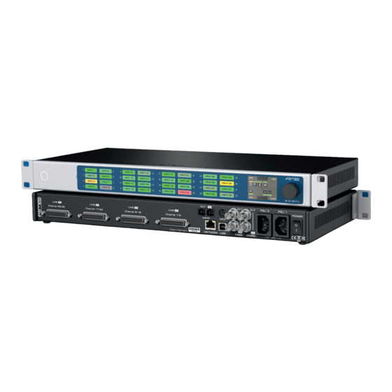
- Page 1 High-end Converter M-32 AD Pro 32-Channel 192 kHz A/D Converter with MADI & AVB I/O User‘s Guide...
- Page 2 RME M-32 AD Pro User’s Guide...
-
Page 3: Table Of Contents
Table of Contents 1. Safety Precautions .............. ... - Page 4 8.3.2. Unlocking the Device ............ ...
-
Page 5: Safety Precautions
RME M-32 AD Pro User’s Guide 1. Safety Precautions WARNING DO NOT OPEN DEVICE - RISK OF ELECTRIC SHOCK The unit has non-isolated live parts inside. No user serviceable parts inside. Refer service to qualified service personnel. WARNING MAGNETIC FIELD The device uses magnets that can be harmful to pacemaker wearers. -
Page 6: Introduction
Each analog channel can be individually adjusted to three different sensitivities that are perfectly matched to the converter’s range. While this is usually implemented with digital 'trims', the M-32 AD Pro does the adjustment in the analog domain, ensuring that the converter’s signal to noise ratio is not reduced when adapting to common line levels. -
Page 7: Use Of The Display And Encoder
The unit retains all settings, including presets, when the firmware is upgraded. 2.2. Use of the Display and Encoder The M-32 AD Pro can be controlled directly at the unit. For this purpose, a display and an encoder provide access to all features. -
Page 8: Tabs
RME M-32 AD Pro User’s Guide 1. Rotate the encoder to highlight the "STATE" section 2. Rotate the encoder to highlight the "INPUT" section 3. Push the encoder to open the "INPUT" section. 2.2.2. Tabs The STATE, INPUT and OUTPUT sections are further divided into tabs, which are shown when the section is opened. -
Page 9: Hardware
RME M-32 AD Pro User’s Guide 3. Hardware Section 3.4, “Standby Switch” Section 3.6, “Channel Labels with Integrated Metering” Section 3.9, “Control Section” Section 3.11, “Analog Line Input Connectors” Section 3.13, “MADI Connectors” Section 3.15, “MIDI Connector” Section 3.16, “Word Clock”... -
Page 10: Hardware Specifications
3.3. Power On The M-32 AD Pro has a power off switch at the rear and a standby switch at the front. Perform the following steps to power on the M-32 AD Pro: 1. Ensure either or both power inlets are properly connected to a power source. -
Page 11: Standby Switch
RME M-32 AD Pro User’s Guide 3.4. Standby Switch The standby switch is used to power off the device when it is not in use. While in standby mode, the device is completely powered down except for a red ring illumination. No signals are processed or passed on. -
Page 12: Channel Labels With Integrated Metering
The use of customized channel labels helps in recurring and permanent installations. They inform the user where the analog connections terminate. The M-32 AD Pro features 32 fields on the front panel, one for each analog input. Integrated backlight in shades of green, yellow, and red represents the current level for each channel. -
Page 13: Control Section
3.10. Power Supplies The M-32 AD Pro has two internal power supplies (PSUs) that are connected via IEC C14 inlets labeled "PSU 1" and "PSU 2" at the rear of the device. Both are hi-performance switch mode power supplies that accept 90V to 264V AC. -
Page 14: Analog Line Input Connectors
3.11. Analog Line Input Connectors The rear of the M-32 AD Pro features four 25-pin D-sub connectors labeled "LINE IN" with Tascam®- pinout. These analog inputs are servo-balanced, allowing balanced and unbalanced signals to be connected without a difference in level. -
Page 15: Ad Converter Specifications
• Channel separation: > 110 dB 3.13. MADI Connectors The rear of the M-32 AD Pro features independent optical and coaxial MADI (AES10-2003) I/O. Each input receives up to 64 audio channels. Auto Input (see Section 9.2.2, “Connecting Two Identical MADI Signals for Redundancy”) can be activated to treat both inputs as one. -
Page 16: Network Connection
• remote status/control with HTTP over IP routed networks. The current link state is also shown on the display of the M-32 AD Pro. A small network port icon between the STATE and INPUT tabs can display the following states:... -
Page 17: Word Clock
3.17. USB 2.0 Type B Jack The USB jack at the rear of the M-32 AD Pro provides an alternative connection method for web remote control when a network connection is not available. -
Page 18: Mounting The Rack Adapter Brackets
RME M-32 AD Pro User’s Guide When connecting the M-32 AD Pro with a standard ("printer") USB 2.0 cable to a current Microsoft Windows™ or Apple macOS™ operating system, a network adapter will be automatically installed. This does not require additional drivers. The device can then be remotely controlled by opening the URL http://172.20.0.1. -
Page 19: Accessories
RME M-32 AD Pro User’s Guide 4. Accessories RME offers several optional components for the M-32 AD Pro: Part Number Description Analog breakout cables AI25-8XPro3 Analog breakout cable 25-pin D-sub to 8 x XLR female, 3 m (9.9 ft) AI25-8XPro5 Analog breakout cable 25-pin D-sub to 8 x XLR female, 5 m (16.4 ft) -
Page 20: Avb Connectivity
RME M-32 AD Pro User’s Guide 5. AVB Connectivity Network Control The M-32 AD Pro is an AVB endpoint device that can be configured with the IEEE Standard for Device Discovery, Connection Management, and Control Protocol for IEEE 1722™ Based Devices, in short: AVDECC. -
Page 21: Changing The Device Name
AVB switch along its way ensures that the audio channels can pass in time, with a higher priority than other network traffic. The M-32 AD Pro supports a total of four streams. Each stream can have a size of 4, 8, 12, and 16 channels. The most common stream size is 8 Channels. -
Page 22: Adjusting The Network Latency
The M-32 AD Pro acts both as a talker with a specified offset of 2 ms, adjustable down to 0.3 ms, and as a listener - where the latency depends on the talker. -
Page 23: Quick Start (Madi)
RME M-32 AD Pro User’s Guide 6. Quick Start (MADI) Follow this procedure to get running quickly! 1. Load Preset 16 (Factory settings) from the STATE section 2. In the CLOCK section, choose a sample rate and verify that the device is clock master or that the chosen clock source is in sync. - Page 24 RME M-32 AD Pro User’s Guide Further steps to enhance your start: State • Section 8.1.1, “Notification of Single Power Failure” • Section 8.2.2, “Loading Presets” • Section 8.3.1, “Locking the Device” • Section 8.4.1, “Dark Mode” • Section 8.5.2, “Web Remote”...
-
Page 25: Warranty And Support
The distributor does not accept claims for damages of any kind, especially consequential damage. Liability is limited to the value of the M-32 AD Pro. The general terms of business drawn up by the distributor apply at all times. - Page 26 RME M-32 AD Pro User’s Guide support@rme-trading.hk Americas Synthax Inc., U.S.A. tech.support@synthax.com Global support@rme-audio.de 7.3. Support Contacts | 22...
-
Page 27: State Section
RME M-32 AD Pro User’s Guide 8. STATE Section The STATE section contains states and settings that are unrelated to audio I/O and clock. It can be used to configure power supply warnings, presets, dark mode, level meters, and remote control. -
Page 28: Presets
Any change in the device configuration is persistent. After a power loss, the device will revert back to its last state. Additionally, the M-32 AD Pro can save fifteen states in presets numbered 1-15. After a preset is loaded, any change in the configuration will result in an unsaved changes state. -
Page 29: Loading Presets
3. Press the Save button 8.2.2. Loading Presets Up to 15 custom presets can be loaded from the internal storage of the M-32 AD Pro. Loading a preset cannot be undone. Ensure that any important configuration has been saved to another preset before proceeding. -
Page 30: Loading Factory Default Settings
STATE section. 8.3. Device Lock The M-32 AD Pro can be secured against both accidental and intentional changes to its configuration. Locking the device, with or without code, protects against changes on the device itself. When locked, the display shows a lock symbol. -
Page 31: Front Panel Illumination
8.4. Front Panel Illumination The M-32 AD Pro features a unique concept for its front panel illumination, which consists of: • A ring illumination around the standby switch that shows the overall state of the device. • 32 channel labels with integrated backlight metering (peak or RMS). -
Page 32: Changing The Meters To Peak Or Rms Mode
RME M-32 AD Pro User’s Guide 1. Connect to the device remotely (see: Section 8.5.1, “Finding the Device on a Network”). Status Indicator State of Visual Feedback Front Panel Dark Mode Global Metering Options Peak/Over Hold Reset 2. Use the corresponding toggle switches on the web remote to switch off device lighting. -
Page 33: Persistent Clipping Notifications
RME M-32 AD Pro User’s Guide 3. Push the "Peak" or "RMS" button in the global metering settings. 8.4.3. Persistent Clipping Notifications In multi-channel applications, it can be important to find out which channel clipped. A clipping is detected when three consecutive samples are digital full scale (0 dBFS). The duration of how long a clipping ("over") event is shown can be manually changed to either five seconds or infinite. -
Page 34: Remote Control Overview
RME M-32 AD Pro User’s Guide 8.5. Remote Control Overview The M-32 AD Pro can be remotely controlled. Remote control is activated by default and is not affected by preset changes or device lock. The network controls over HTTP and AVDECC operate simultaneously. Two or more controller instances are synchronized. -
Page 35: Web Remote
8.5.2. Web Remote An integrated web server provides an easy-to-use remote control interface for the M-32 AD Pro. It requires a network connection from a desktop computer with a current browser version. Compatible browsers: •... - Page 36 RME M-32 AD Pro User’s Guide Web Remote Overview Section 8.1, “Power State” Section 8.2, “Presets” Section 8.4, “Front Panel Illumination” Section 11.1, “Clock status” Section 5.1, “Identifying a Device Remotely” Settings: Device name, Firmware update, etc. Section 5.2, “Changing the Device Name”...
-
Page 37: Device Information
RME M-32 AD Pro User’s Guide 8.6. Device Information The information tab is located in the STATE section. It shows the current firmware version and gPTP Grandmaster ID. 8.6. Device Information | 33... -
Page 38: Input Section
9.1. Analog Inputs The line level inputs of the M-32 AD Pro accept levels of up to +24 dBu. Each individual channel has its own line level setting of +13/+19/+24 dBu which can also be adjusted remotely. Additionally, the AD converters can be globally set to standby (mute). -
Page 39: Adc Converter Mute
2. Toggle the ADC Standby switch to 9.2. MADI Input The M-32 AD Pro accepts up to two MADI signals, one electrical (BNC input) and one optical (SC input). To connect a MADI signal: 1. Ensure that you have set the correct sample rate and clock source in the CLOCK section. -
Page 40: Connecting Two Identical Madi Signals For Redundancy
SYNC and LOCK states are evaluated to confirm the current input state. It is therefore possible to send two different signals to the M-32 AD Pro as long as they are in sync. To create MADI redundancy: 1. Switch on "enable MADI redundancy" in the coaxial tab of the INPUT section. The port will be renamed to MADI Auto Input. -
Page 41: Avb Input Streams
2. Toggle the switch "Auto Input" to ON. 9.3. AVB Input Streams The AVB streams received by the M-32 AD Pro are referred to as "input streams". For these streams, the device acts as an AVB Listener. To establish a connection between a talker and a listener, an AVDECC Controller is required. The M-32 AD Pro does not include an AVDECC Controller. - Page 42 RME M-32 AD Pro User’s Guide 3. Rotate the encoder to configure a new stream size and confirm by pressing the encoder again. To change the amount of channels in the incoming AVB stream with the web remote: 1. Connect the device by USB or network cable and open the web remote.
-
Page 43: Output Section
Example: In the OUTPUT section, MADI Optical 1-12 is chosen as source for AVB Stream 2. The M-32 AD Pro is clock master, but the incoming MADI signal is not correctly synchronized. This causes a warning in the INPUT section. -
Page 44: Madi Outputs
RME M-32 AD Pro User’s Guide 10.1. MADI Outputs The MADI outputs of the M-32 AD Pro are always active. If no routing is configured, an empty stream is sent that can be used for clocking. This state is represented with a light-green Status Indicator. -
Page 45: Madi Daisy Chains
BNC coaxial and SC optical ports. The M-32 AD Pro features independent routing for both MADI output ports. For this reason, a "mirroring" of the signal must be manually created. In order to do this, the routing of the two MADI outputs should be configured to contain the same routing. -
Page 46: Avb Output Streams
This is set per default to 2 ms. The output streams of the M-32 AD Pro are by default empty, containing a clock signal but no audio signal. To send audio with AVB, a routing must be created for each outgoing stream. - Page 47 RME M-32 AD Pro User’s Guide 2. Open an AVB port in the routing area and use the up and down arrows to adjust the stream size 3. Click Apply. Changing a stream size briefly interrupts all incoming and outgoing AVB streams.
-
Page 48: Clock Section
11.2. Master Clock In its the default state, the M-32 AD Pro uses an internal clock signal (master). This means that any connected device must synchronize to it (slave). Alternatively, one of the digital inputs (word clock, MADI optical, MADI coaxial, and each of the four AVB... -
Page 49: Selecting A Master Clock
Intelligent Clock Control (ICC) automatically changes the clock source when the chosen master clock fails. Using the feedback of SyncCheck™, the M-32 AD Pro will change to another source signal that is in sync, maintaining the slave mode and current sample rate. If no other source is available, the device will fall back to its internal clock until the chosen master has recovered. -
Page 50: Slave Mode
RME M-32 AD Pro User’s Guide 11.3.1. Slave Mode When the device is slave, certain deviations are automatically accepted to avoid interruption of the outgoing audio signal when the sample rate changes. This is called Intelligent Clock Control (ICC). It also handles deriving a sample rate of double or quad speed based on an incoming rate. -
Page 51: Number Of Channels
RME M-32 AD Pro User’s Guide Word Clock 44.1, 88.2, 176.4 176.4 176.4 Word Clock 44.1, 88.2, 176.4 176.4 with warning Word Clock 44.1 48 with warning Word Clock Word Clock 48, 96 88.2 96 with warning Word Clock 48, 96... -
Page 52: Selecting A Sample Rate
11.3.4. Effects of Sample Rate Changes on Existing Routing The M-32 AD Pro saves one routing table per preset, regardless of sample rate. A change of sample rate or MADI frame mode can reduce the number of input and output channels available for routing. This does not alter the routing table. - Page 53 RME M-32 AD Pro User’s Guide Sample Rate Word Clock Full Speed (default) Word Clock Single Speed (option) 96 kHz 96 kHz 48 kHz 176.4 kHz 176.4 kHz 44.1 kHz 192 kHz 192 kHz 48 kHz To set the Word Clock output to single speed on the device: 1.
-
Page 54: Annex
RME M-32 AD Pro User’s Guide 12. Annex Trademarks and Copyright All trademarks, registered or otherwise, are the property of their respective owners. RME is a registered trademark of RME Intelligent Audio Solutions. SyncCheck, SteadyClock, ICC, Intelligent Clock Control and Digiface are trademarks of RME Intelligent Audio Solutions. -
Page 55: Table
RME M-32 AD Pro User’s Guide Format: F0 00 20 0D 32 (bank no. / dev ID) 10 F7 This string triggers a complete dump of all value response data bytes including the level meter data. Set Value Sets any number of parameters. nn / oo can be repeated freely. - Page 56 RME M-32 AD Pro User’s Guide Name Val. Data bytes Val. Resp level ch 18 (see below) level ch 19 (see below) level ch 20 (see below) level ch 21 (see below) level ch 22 ...
- Page 57 RME M-32 AD Pro User’s Guide settings byte 1 MSB / 7 follow clock: 0 = off, 1 = on MSB / 1 clock state: 0 = single speed, 1 = ds, 2 = qs ...
- Page 58 RME M-32 AD Pro User’s Guide level meter data LSB / LSB / Level level steps: ...
-
Page 59: Declarations Of Conformity
Responsible Party in USA: Synthax United States, 6600 NW 16th Street, Suite 10, Ft Lauderdale, FL 33313 T.:754.206.4220 Trade Name: RME, Model Number: M-32 AD Pro 12.2.3. Note on Disposal According to the guide line RL2002/96/EG (WEEE – Directive on Waste Electrical and Electronic Equipment), valid for all european countries, this product has to be recycled at the end of its lifetime.
Need help?
Do you have a question about the M-32 AD Pro and is the answer not in the manual?
Questions and answers