
Related Manuals for RME Audio M-32 MIDI DA Pro


Summary of Contents for RME Audio M-32 MIDI DA Pro
- Page 1 High-end Converter M-32 DA Pro 32-Channel 192 kHz D/A Converter with MADI & AVB I/O User‘s Guide...
- Page 2 RME M-32 DA Pro User’s Guide...
-
Page 3: Table Of Contents
Table of Contents 1. Safety Precautions .............. ... - Page 4 8.3.2. Unlocking the Device ............ ...
-
Page 5: Safety Precautions
RME M-32 DA Pro User’s Guide 1. Safety Precautions WARNING DO NOT OPEN DEVICE - RISK OF ELECTRIC SHOCK The unit has non-isolated live parts inside. No user serviceable parts inside. Refer service to qualified service personnel. WARNING MAGNETIC FIELD The device uses magnets that can be harmful to pacemaker wearers. -
Page 6: Introduction
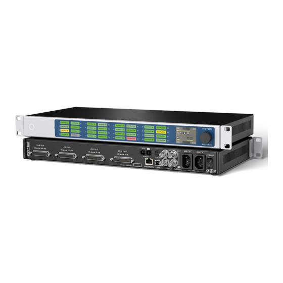
RME M-32 DA Pro User’s Guide 2. Introduction Thank you for purchasing the M-32 DA Pro. The M-32 DA Pro is a versatile multichannel format converter with exceptional audio quality across each of its channels. State-of-the art components from audiophile grade converters have been carefully aligned to fit into a compact, 1 HU 19"... -
Page 7: Use Of The Display And Encoder
RME M-32 DA Pro User’s Guide 5. Within the Firmware Update section, press the Select .swu Firmware File button and locate the unpacked file. 6. Press Start Firmware Update. The unit retains all settings, including presets, when the firmware is upgraded. 2.2. -
Page 8: Tabs
RME M-32 DA Pro User’s Guide 1. Rotate the encoder to highlight the "STATE" section 2. Rotate the encoder to highlight the "INPUT" section 3. Push the encoder to open the "INPUT" section. 2.2.2. Tabs The STATE, INPUT and OUTPUT sections are further divided into tabs, which are shown when the section is opened. -
Page 9: Hardware
RME M-32 DA Pro User’s Guide 3. Hardware Section 3.4, “Standby Switch” Section 3.6, “Channel Labels with Integrated Metering” Section 3.9, “Control Section” Section 3.11, “Analog Line Output Connectors” Section 3.13, “MADI Connectors” Section 3.15, “MIDI Connector” Section 3.16, “Word Clock” Section 3.14, “Network Connection”... -
Page 10: Hardware Specifications
RME M-32 DA Pro User’s Guide 3.1. Hardware Specifications RME M-32 DA Pro 42 6012336 322 2 Dimensions 440 x 44 x 243 mm (17.3 x 1.7 x 9.6 inches) Weight 2.8 kg (6.2 lbs) Package 560 x 315 x 115 mm (22.1 x 12.4 x 4.5 inches) Conformity CE, FCC, WEEE, RoHS Power supplies... -
Page 11: Standby Switch
RME M-32 DA Pro User’s Guide 3.4. Standby Switch The standby switch is used to power off the device when it is not in use. While in standby mode, the device is completely powered down except for a red ring illumination. No signals are processed or passed on. -
Page 12: Channel Labels With Integrated Metering
RME M-32 DA Pro User’s Guide 3.6. Channel Labels with Integrated Metering The use of customized channel labels helps in recurring and permanent installations. They inform the user where the analog connections terminate. The M-32 DA Pro features 32 fields on the front panel, one for each analog output. Integrated backlight in shades of green, yellow, and red represents the current level for each channel. -
Page 13: Control Section
RME M-32 DA Pro User’s Guide 2. Remove the current label sheet that is held between cover and device. 3. Place a new label sheet onto the cover. 4. Put the cover back into its place, aligning the centered metal plate first. It snaps into place magnetically. -
Page 14: Analog Line Output Connectors
RME M-32 DA Pro User’s Guide The inlets are labeled in the sequence they appear when looking from the front of the device. This helps identifying the active power source on the display. The power switch next to the two inlets internally disconnects the line connection of the C14 inlets to the power supplies. -
Page 15: Da Converter Specifications
RME M-32 DA Pro User’s Guide When set to +24, analog outputs comply with RP 155:2014 - SMPTE Recommended Practice. 3.12.1. DA Converter Specifications Line Out 1-32: • Resolution: 24 bit • Output level switchable per channel +24 dBu, +19 dBu, +13 dBu @ 0 dBFS •... -
Page 16: Network Connection
RME M-32 DA Pro User’s Guide 3.14. Network Connection On the rear of the M-32 DA Pro, an RJ45 connector labeled NETWORK provides a connection to ethernet. Two link speeds are supported: 100 Mb/s and 1 Gb/s. A green LED (left) signals network traffic (blinking). A yellow LED (right) signals a successful link. Both straight and crossover cables can be used (Auto MDI-X). -
Page 17: Word Clock
RME M-32 DA Pro User’s Guide MIDI Breakout Cable Wiring Diagram The M-32 DA Pro does not serve as a MIDI to/from MIDI over MADI converter. It does not pass on incoming MIDI signals except for SysEx remote control information. 3.16. -
Page 18: Mounting The Rack Adapter Brackets
RME M-32 DA Pro User’s Guide When connecting the M-32 DA Pro with a standard ("printer") USB 2.0 cable to a current Microsoft Windows™ or Apple macOS™ operating system, a network adapter will be automatically installed. This does not require additional drivers. The device can then be remotely controlled by opening the URL http://172.20.0.1. -
Page 19: Accessories
RME M-32 DA Pro User’s Guide 4. Accessories RME offers several optional components for the M-32 DA Pro: Part Number Description Analog breakout cables AO25-8XPro3 Analog breakout cable 25-pin D-sub to 8 x XLR male, 3 m (9.9 ft) AO25-8XPro5 Analog breakout cable 25-pin D-sub to 8 x XLR male, 5 m (16.4 ft) AO25-8XPro10 Analog breakout cable 25-pin D-sub to 8 x XLR male, 10 m (33 ft) -
Page 20: Avb Connectivity
RME M-32 DA Pro User’s Guide 5. AVB Connectivity Network Control The M-32 DA Pro is an AVB endpoint device that can be configured with the IEEE Standard for Device Discovery, Connection Management, and Control Protocol for IEEE 1722™ Based Devices, in short: AVDECC. -
Page 21: Changing The Device Name
RME M-32 DA Pro User’s Guide 1. Open an M-32 DA Pro web remote in a browser 2. Press the identify icon. The front panel level meters of the controlled device will show an animation. Depending on the controller, the animation may persist infinitely or stop after a short period of time. -
Page 22: Adjusting The Network Latency
RME M-32 DA Pro User’s Guide The receiver compares the incoming presentation time of each sample to the current time and buffers the sample until the presentation time is has come. The offset (maximum transit time) is specified by the AVB standard as 2 ms for class A traffic, which is enough time for the signal to pass through a very large network under full load with up to seven 100 MBit/s switches along the way. -
Page 23: Quick Start (Madi)
RME M-32 DA Pro User’s Guide 6. Quick Start (MADI) Follow this procedure to get running quickly! 1. Load Preset 16 (Factory settings) from the STATE section 2. In the CLOCK section, choose a sample rate and verify that the device is clock master or that the chosen clock source is in sync. - Page 24 RME M-32 DA Pro User’s Guide Further steps to enhance your start: State • Section 8.1.1, “Notification of Single Power Failure” • Section 8.2.2, “Loading Presets” • Section 8.3.1, “Locking the Device” • Section 8.4.1, “Dark Mode” • Section 8.5.2, “Web Remote” •...
-
Page 25: Warranty And Support
RME M-32 DA Pro User’s Guide 7. Warranty and Support 7.1. Warranty Each individual M-32 DA Pro undergoes comprehensive quality control and a complete test before shipping. The usage of high grade components should guarantee a long and trouble-free operation of the unit. - Page 26 RME M-32 DA Pro User’s Guide support@rme-trading.hk Americas Synthax Inc., U.S.A. tech.support@synthax.com Global support@rme-audio.de 7.3. Support Contacts | 22...
-
Page 27: State Section
RME M-32 DA Pro User’s Guide 8. STATE Section The STATE section contains states and settings that are unrelated to audio I/O and clock. It can be used to configure power supply warnings, presets, dark mode, level meters, and remote control. A warning (red) is shown when PSU redundancy is activated but only one power supply is active. -
Page 28: Presets
RME M-32 DA Pro User’s Guide Power loss at PSU 2 To activate the warning on the device: 1. Open the power tab in the STATE section. 2. Toggle the switch Redundancy to On. The warning signals only the current state. To activate the warning on the web remote: 1. -
Page 29: Loading Presets
RME M-32 DA Pro User’s Guide 2. Push and rotate the encoder to choose a preset number. 3. Push Save to save the preset. To save a preset using the web remote: 1. Open the web remote and locate the preset tab. Status Indicator Current preset and state Preset drop-down menu... -
Page 30: Loading Factory Default Settings
RME M-32 DA Pro User’s Guide 3. Press the Load Button 8.2.3. Loading Factory Default Settings The factory default settings are saved internally as Preset 16 and cannot be overwritten. To load the factory defaults, load Preset 16. Loading the factory defaults does not delete any saved presets. It also does not affect the lock settings in the STATE section. -
Page 31: Front Panel Illumination
RME M-32 DA Pro User’s Guide 2. (if a code was set) Enter the code and choose "Done". The device will lock again after a timeout of one minute. To unlock the device permanently: 1. Proceed as above, then 2. Open the lock tab in the STATE section 3. -
Page 32: Changing The Meters To Peak Or Rms Mode
RME M-32 DA Pro User’s Guide 1. Connect to the device remotely (see: Section 8.5.1, “Finding the Device on a Network”). Status Indicator State of Visual Feedback Front Panel Dark Mode Global Metering Options Peak/Over Hold Reset 2. Use the corresponding toggle switches on the web remote to switch off device lighting. 8.4.2. -
Page 33: Persistent Clipping Notifications
RME M-32 DA Pro User’s Guide 3. Push the "Peak" or "RMS" button in the global metering settings. 8.4.3. Persistent Clipping Notifications In multi-channel applications, it can be important to find out which channel clipped. A clipping is detected when three consecutive samples are digital full scale (0 dBFS). The duration of how long a clipping ("over") event is shown can be manually changed to either five seconds or infinite. -
Page 34: Remote Control Overview
RME M-32 DA Pro User’s Guide 8.5. Remote Control Overview The M-32 DA Pro can be remotely controlled. Remote control is activated by default and is not affected by preset changes or device lock. The network controls over HTTP and AVDECC operate simultaneously. Two or more controller instances are synchronized. -
Page 35: Web Remote
RME M-32 DA Pro User’s Guide 2. The current IP address is displayed. 3. Enter the IP address in the address bar. Connecting to the Remote Interface without IP address Instead of using the IP address, the device name can be entered in the browser window, followed by .local./. - Page 36 RME M-32 DA Pro User’s Guide Web Remote Overview Section 8.1, “Power State” Section 8.2, “Presets” Section 8.4, “Front Panel Illumination” Section 11.1, “Clock status” Section 5.1, “Identifying a Device Remotely” Settings: Device name, Firmware update, etc. Section 5.2, “Changing the Device Name” Section 10.1, “Analog Outputs”...
-
Page 37: Device Information
RME M-32 DA Pro User’s Guide 8.6. Device Information The information tab is located in the STATE section. It shows the current firmware version and gPTP Grandmaster ID. 8.6. Device Information | 33... -
Page 38: Input Section
RME M-32 DA Pro User’s Guide 9. INPUT Section The input section is used to inspect and configure the audio inputs of the device. A warning is displayed when an input is not present but selected as clock master, or routed to an output and is either not present or not in sync to the clock master. -
Page 39: Connecting Two Identical Madi Signals For Redundancy
RME M-32 DA Pro User’s Guide samples for channel 2, and so forth. The amount of channels corresponds to the same as the 96k frame. This format cannot be automatically detected at the receiver side. Quad Speed (176.4 kHz, 196 kHz) Quad speed MADI does not have a standardized frame format. -
Page 40: Change Avb Input Stream Size
RME M-32 DA Pro User’s Guide To establish a connection between a talker and a listener, an AVDECC Controller is required. The M-32 DA Pro does not include an AVDECC Controller. AVB input streams are monitored as follows: Description Indicator Possible solution Disabled grey... - Page 41 RME M-32 DA Pro User’s Guide 3. Adjust the stream size to 4, 8, 12 or 16 channels and click 'Apply'. Changing a stream size briefly interrupts all incoming and outgoing AVB streams. 9.2. AVB Input Streams | 37...
-
Page 42: Output Section
RME M-32 DA Pro User’s Guide 10. OUTPUT Section The output section represents the internal routing matrix and state of the outputs. Routing is performed by selecting an output and assigning any input to it. When a routing is active, its input is automatically monitored for lock and sync in the input section. -
Page 43: Analog Outputs
RME M-32 DA Pro User’s Guide 10.1. Analog Outputs The line level outputs of the M-32 DA Pro operate at +13 dBu, +19 dBu, or +24 dBu. Each individual channel has its own line level setting, which can be adjusted remotely. Additionally, channels can be muted globally or individually. -
Page 44: Mute Analog Outputs
RME M-32 DA Pro User’s Guide 5. Rotate the encoder to change the setting and confirm by pushing the encoder again. To adjust the output line level on the web remote: 1. Select either a single channel or two channels by clicking the corresponding level meter. All inputs between the two selected channels will be automatically included in the selection. -
Page 45: Setting The Output Channel Format And Frame Pattern
RME M-32 DA Pro User’s Guide 10.2.1. Setting the Output Channel Format and Frame Pattern Depending on the requirements of the receiver, it is possible to change the channel format and frame pattern of the outgoing MADI streams. To change the channel format of both MADI outputs on the device: 1. -
Page 46: Madi Daisy Chains
RME M-32 DA Pro User’s Guide 3. Press the encoder to open the routing. The cursor will highlight the first available channel block. 4. Either rotate the encoder to select the next available channel block or press it to start assigning the source signal. -
Page 47: Avb Output Streams
RME M-32 DA Pro User’s Guide 10.3. AVB Output Streams The AVB streams leaving the M-32 DA Pro are described as "output streams". In this case, the device acts as a talker. The talker defines the presentation time and therefore the latency across the network. This is set per default to 2 ms. - Page 48 RME M-32 DA Pro User’s Guide 3. Click Apply. Changing a stream size briefly interrupts all incoming and outgoing AVB streams. 10.3. AVB Output Streams | 44...
-
Page 49: Clock Section
RME M-32 DA Pro User’s Guide 11. CLOCK Section The CLOCK section is used to inspect and configure the clock source and sample rate of the M-32 DA Pro. Web remote Status Indicator Selected Master (frame) Word Clock Output Single Speed Setting Current Master (white) Current Master and Sample Rate Master Selection Dropdown... -
Page 50: Selecting A Master Clock
RME M-32 DA Pro User’s Guide streams) can be chosen as clock reference. This activates SteadyClock™ FS, a technology that extracts a low jitter clock signal from the incoming signal. Intelligent Clock Control (ICC) automatically changes the clock source when the chosen master clock fails. -
Page 51: Slave Mode
RME M-32 DA Pro User’s Guide 11.3.1. Slave Mode When the device is slave, certain deviations are automatically accepted to avoid interruption of the outgoing audio signal when the sample rate changes. This is called Intelligent Clock Control (ICC). It also handles deriving a sample rate of double or quad speed based on an incoming rate. -
Page 52: Number Of Channels
RME M-32 DA Pro User’s Guide Word Clock 44.1, 88.2, 176.4 176.4 176.4 Word Clock 44.1, 88.2, 176.4 176.4 with warning Word Clock 44.1 48 with warning Word Clock Word Clock 48, 96 88.2 96 with warning Word Clock 48, 96 Word Clock 48, 96, 192 176.4... -
Page 53: Selecting A Sample Rate
RME M-32 DA Pro User’s Guide Since there are two independent MADI ports, the total supported number of channels can be multiplied by two. Since there are four independent AVB streams, the total supported number of channels can be multiplied by four. The analog channel count is always 32 regardless of sample rate. - Page 54 RME M-32 DA Pro User’s Guide Sample Rate Word Clock Full Speed (default) Word Clock Single Speed (option) 96 kHz 96 kHz 48 kHz 176.4 kHz 176.4 kHz 44.1 kHz 192 kHz 192 kHz 48 kHz To set the Word Clock output to single speed on the device: 1.
-
Page 55: Annex
RME M-32 DA Pro User’s Guide 12. Annex Trademarks and Copyright All trademarks, registered or otherwise, are the property of their respective owners. RME is a registered trademark of RME Intelligent Audio Solutions. SyncCheck, SteadyClock, ICC, Intelligent Clock Control and Digiface are trademarks of RME Intelligent Audio Solutions. -
Page 56: Table
RME M-32 DA Pro User’s Guide Format: F0 00 20 0D 32 (bank no. / dev ID) 10 F7 This string triggers a complete dump of all value response data bytes including the level meter data. Set Value Sets any number of parameters. nn / oo can be repeated freely. Value Response After being triggered by receiving a request value command, device sends a string of all value response data bytes. - Page 57 RME M-32 DA Pro User’s Guide Name Val. Data bytes Val. Resp level ch 18 (see below) level ch 19 (see below) level ch 20 (see below) level ch 21 (see below) level ch 22 (see below) level ch 23 ...
- Page 58 RME M-32 DA Pro User’s Guide settings byte 1 MSB / 7 follow clock: 0 = off, 1 = on MSB / 1 clock state: 0 = single speed, 1 = ds, 2 = qs ...
- Page 59 RME M-32 DA Pro User’s Guide level meter data LSB / LSB / Level level steps: ...
-
Page 60: Declarations Of Conformity
RME M-32 DA Pro User’s Guide 12.2. Declarations of conformity 12.2.1. CE Compliance This device has been tested and found to comply with the limits of the European Council Directive on the approximation of the laws of the member states relating to electromagnetic compatibility according to RL2014/30/EU, and European Low Voltage Directive RL2014/35/EU.
Need help?
Do you have a question about the M-32 MIDI DA Pro and is the answer not in the manual?
Questions and answers