Table of Contents
Advertisement
Quick Links
Advertisement
Table of Contents

Related Manuals for DFI EC531


Summary of Contents for DFI EC531
- Page 1 EC531/532-SD User’s Manual A-457-M-2008 www.dfi.com...
-
Page 2: Trademarks
Product names or trademarks appearing in this manual are for identification purpose only and Shielded interface cables must be used in order to comply with the emission limits. are the properties of the respective owners. www.dfi.com... -
Page 3: Table Of Contents
S/PDIF Connector ..................28 Specifications ................7 LPC Connector .................... 28 Expansion Slots ..................29 Getting to Know the EC531/EC532-SD ........8 12V DC-out ....................30 Digital I/O Connector (daughter board) ............31 Mechanical Dimensions ............9 COM (Serial) Ports (daughter board) ............31 Chapter 2 - Getting Started ........ -
Page 4: About This Manual
About this Manual Static Electricity Precautions An electronic file of this manual can be obtained from the DFI website at www.dfi.com. It is quite easy to inadvertently damage your PC, system board, components or devices even To download the user’s manual from our website, please go to “Support” > “Download Center.”... -
Page 5: Safety Precautions
• Unplug the power cord before removing the system chassis cover for installation or servic- ing. After installation or servicing, cover the system chassis before plugging the power cord. • 1 EC531/EC532-SD system unit • 1 Quick Installation Guide • Danger of explosion if battery incorrectly replaced. -
Page 6: Chapter 1 -Introduction
Chapter 1 Chapter 1 -Introduction Key Features Overview Model Name EC531/EC532-SD Processor ® 6th Generation Intel Core processors Chipset Intel H110 Chipset or Intel Q170 Chipset ® ® 2 LAN ports 6 COM ports Display DVI (DVI-D signal) HDMI or DP (DP available upon request) 8 USB 3.0 Type A ports... -
Page 7: Specifications
Standards and IEC68-2-64 Certifications Notes: This HDMI or DP port is only available for the Intel Q170 Chipset. ® Please contact your sales representative for more information on the mounting kit, which is not included in the standard model. www.dfi.com... -
Page 8: Getting To Know The Ec531/Ec532-Sd
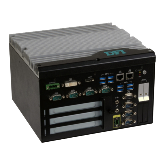
Chapter 1 Getting to Know the EC531/EC532-SD Front I/O Ports Power Button with LED (Green) Front View Press to power on or power off the system. HDMI DVI-I Reset Button (DVI-D signal) DC-in USB 3.0 Press to reset the system. -
Page 9: Mechanical Dimensions
Chapter 1 Mechanical Dimensions Chassis Dimensions Motherboard Dimensions 209.55 Rear View Gold finger PCIE X4 Gold finger PCIE X16 mini PCIe Left View Right View Front View www.dfi.com... -
Page 10: Chapter 2 - Getting Started
Please refer to your operating system manual for instructions on installing an operating system. Installing the Drivers The system requires you to install drivers for some devices to operate properly. Refer to the Supported Software chapter for instructions on installing the drivers. www.dfi.com... -
Page 11: Chapter 3 - Installing The Devices
SATA 2 SATA 1 Notes: The slot is desgined to exactly fit a 2.5" SATA drive with 7mm thickness; it cannot fit SATA drives with other sizes. Do not force to close the drive bay if the HDD is not correctly inserted. www.dfi.com... - Page 12 Expansion Slots Sequence EC531-SD Below figure shows the expansion slots of PCIe, PCI, PCI (from top to bottom) Slot Plate PCIe 1 (x16) PCI 1 PCI 2 Mounting Screw and Bracket EC532-SD Below figure shows the expansion slots of PCIe, PCI, PCI (from top to bottom)
-
Page 13: Removing The Chassis Cover
The 4 mounting screws on the bottom of the system are used to secure the cover to the chassis. Remove these screws and put them in a safe place for later use. Mounting screw Mounting screw Supporting bracket Lift the cover upward to open the system. SODIMM socket www.dfi.com... -
Page 14: Installing A Mini Pcie Or Msata Card
Notes: The system supports dual-channel configuration. To enable dual-channel, populate both SODIMM sockets. The SODIMM sockets can only accept DDR4 memory modules. Please do not install other types of memory modules. 0.82mm www.dfi.com... -
Page 15: Installing A Pci Or Pcie Expansion Card
1. PCI and PCIe slots on the riser card inside the system are used to install the expansion cards. To install the expansion cards, you need to first remove the slot plates and bracket by uninstalling the mounting screws on the front chassis. Slot plate Mounting screw and bracket www.dfi.com... -
Page 16: Installing A Cpu
2. Keep the protective cap. RMA requests will be accepted and processed only if the LGA 1151 socket comes with the protective cap. 5. Unlock the socket by pushing the load lever down, move it sideways until it is released from the retention tab, and then lift the load lever up. www.dfi.com... - Page 17 9. Insert the CPU into the socket. The gold triangular mark on the CPU must align with the corner of the CPU socket as shown below. The CPU’s notch will at the same time fit into the socket’s alignment key. Alignment key Gold triangular mark www.dfi.com...
- Page 18 4 mounting holes around the socket. 3. Orient the heat sink such that the CPU fan’s cable is nearest the CPU fan con- nector. www.dfi.com...
-
Page 19: Chapter 4 - Jumper Settings
1. Power-off the system and unplug the power cord. 2. Set the jumper pins 2 and 3 to On. Wait for a few seconds and set the jumper back to its default setting: 1-2 On. 3. Now plug the power cord and power on the system. www.dfi.com... -
Page 20: Com1/Com2 Rs232 Power Select (Maindboard)
RS232 or RS232 with power. The pin assignments (Pin 1: optional 12V and COM1 and COM2 will vary according to JP3’s and JP2’s setting respectively. Pin 9: optional 5V) of COM4 and COM5 will vary according to JP7’s and JP11’s setting respec- tively. www.dfi.com... -
Page 21: Com1 /Com2 /Com3 Rs232/422/485 Select (Mainboard)
1. When COM1 RS232/422/485 is selected, JP5 and JP12 must be set in accordance to JP6. 2. When COM2 RS232/422/485 is selected, JP7 and JP14 must be set in accordance to JP13. 3. When COM3 RS232/422/485 is selected, JP8 and JP15 must be set in accordance to JP9. www.dfi.com... -
Page 22: Com4 /Com5 /Com6 Rs232/422/485 Select (Daughter Board)
RS422 Full Duplex/RS485 RS232 (default) 2. When COM 5 RS232/422/485 is selected, JP9 and JP10 must be set in accordance to JP8. 3. When COM 6 RS232/422/485 is selected, JP13 and JP14 must be set in accordance to JP12. www.dfi.com... -
Page 23: Chapter 5 - Ports And Connectors
BIOS. Refer to Chapter 7 for more information. • Storage: two SATA drive bays The front panel I/O consists of the following ports from the daughter board: • USB: four USB 3.0 ports • Serial: three serial COM ports • Digital input/output: one 8-bit DIO port www.dfi.com... -
Page 24: Com (Serial) Ports (Mainboard)
• BIOS Setting Configure the serial ports with advanced options such as the RS485 auto flow mechanism in the Advanced menu (“Super IO Configuration” submenu) of the BIOS. Refer to Chapter 7 for more information. www.dfi.com... -
Page 25: Rj45 Lan Ports
Install the LAN drivers. Refer to Chapter 8 for more information. BIOS Setting Configure the display devices in the Advanced menu (“Video Configuration” submenu) of the BIOS. Refer to Chapter 7 for more information. Driver Installation Install the graphics driver. Refer to Chapter 8 for more information. www.dfi.com... -
Page 26: I/O Connectors
(Extended Capabilities Port) transfer rate. Allows bidirectional parallel port operation at BIOS Setting maximum speed. (Enhanced Parallel Port) Configure the Serial ATA drives in the Advanced menu (“SATA Confiuration” submenu) of the BIOS. Refer to Chapter 7 for more information. www.dfi.com... -
Page 27: Sata (Serial Ata) Power Connectors
SATA power connector and the other end to your storage device. one to act as a master by initiating data transfer. www.dfi.com... -
Page 28: Cooling Fan Connectors
Digital I/O Connector The Super IO menu (“PC Health Status” submenu) of the BIOS will display the current speed Pins of the cooling fans. Refer to Chapter 7 for more information. DIO7 DIO6 DIO5 DIO4 DIO3 DIO2 DIO1 DIO0 www.dfi.com... -
Page 29: Audio Connector
This jack is used to connect an external microphone. Pin Pin Assignment Pin Pin Assignment Driver Installation HDD Power LED Power HDD-LED Install the audio driver. Refer to Chapter 8 for more information. Signal LED Power PWR-LED Ground Signal RST Signal Ground RESET SW ATX-SW N.C. Signal www.dfi.com... -
Page 30: S/Pdif Connector
24MHz LPC bus clock. For more information about LPC bus, please refer to the Intel Low Pin ® Count Interface Specification Revision 1.1’. The table below indicates the pin functions of the LPC connector. Pin Assignment Pin Assignment L_CLK L_AD1 L_RST# L_AD0 L_FRAME# L_AD3 L_AD2 INT_SERIRQ 5VSB www.dfi.com... -
Page 31: Expansion Slots
PCI Express x16 Slot/PCI Express x4 Connector DPB_HPD Reserved The system offers two types of riser cards. The EC531-SD is pre-installed with the H320- DPB_LAN3_n LPC_FRAME# 2P1E riser card that provides one PCIe x16 and two PCI slots. Whereas the EC532-SD is pre-... -
Page 32: 12V Dc-Out
SATA_TXp 4-pin power GND1 PCIE_ECX_TX3p Reserved GND2 PCIe x16 (PCIE1) DC-in PCIe x4 (PCIE2) SMB_CLK_RESUME DFI Board ID_0 SMB_DATA_RESUME DFI Board ID_1 INT_GPIO# DFI Board ID_2 PCIe_Wake# SATA_RXn INT_SERIRQ SATA_RXp The 4-pin vertical type connector (optional) provides low power output. -
Page 33: Digital I/O Connector (Daughter Board)
Configure the serial ports with advanced options such as the RS485 auto flow mechanism in DIO9 the Advanced menu (“Super IO Configuration” submenu) of the BIOS. Refer to Chapter 7 for more information. DIO10 DIO11 DIO12 DIO13 DIO14 DIO15 www.dfi.com... -
Page 34: Usb Ports (Daughter Board)
The daughter board provides 4 extra USB 3.0 ports to the system. USB 3.0 can transfer data up to 5 Gbps. • BIOS Setting Configure the onboard USB in the Advanced menu (“USB Configuration” submenu) of the BIOS. Refer to Chapter 7 for more information. www.dfi.com... -
Page 35: Chapter 6 - Mounting Options
The following illustration shows the location and dimension of the holes for mounting the device 1. The wall mounting holes are located on the bottom of the system unit. onto a wall or rack . Mounting hole Mounting hole www.dfi.com... -
Page 36: Chapter 7 - Bios Setup
“Reset” button. You may also additional options are available for that field. To display the submenu, move the highlight to restart the system by pressing the <Ctrl> <Alt> and <Del> keys simultaneously. that field and press <Enter>. www.dfi.com... -
Page 37: Main
The time format is <hour>, <minute>, <second>. The time is based on the 24-hour military-time clock. For example, 1 p.m. is 13:00:00. Hour displays hours from 00 to 23. Minute displays minutes from 00 to 59. Second displays seconds from 00 to 59. www.dfi.com... - Page 38 The system appears to be off when power is re-applied after AC power loss. Wake on RTC Automatically power the system on at a particular time every day from the Real-time clock battery. Specify the wake up time of the day below: <hour> (00~23), <minute> (00~59), <second> (00~59). www.dfi.com...
- Page 39 H110 Chipset. Note that this option only ap- ® pears when the boot type selected is dual or legacy boot type. Internal Graphics Enable, disable or to automatically detect internal graphics. Always Enabled PEG Enable or disable the PCIe graphics function. www.dfi.com...
- Page 40 The high-definition audio will be enabled if present and disabled otherwise. Intel Q170 Chipset. ® Serial ATA Port 0, 1 and 2 Enable or disable each serial ATA port: SATA Port 0 controls SATA3_0 SATA Port 1 controls SATA3_1 SATA Port 2 controls the half-size Mini PCIe slot www.dfi.com...
- Page 41 PCIe Root Port 8 controls PCIE2 (x4) connector Disable the USB keyboard/mouse/storage support. PCIe Speed Enabled Select the speed of the PCI Express Root Port: Auto, Gen1, Gen2 or Gen3. Enable the USB keyboard/mouse/storage support. UEFI Only Enable the USB keyboard/mouse/storage support only under UEFI environment. www.dfi.com...
- Page 42 Me Fw Image Re-Flash Intel AMT Support Enable or disable flashing of the Intel ME region. ® Enable or disable Intel Active Management Technology BIOS extension. ® Un-Configure ME Clears all ME related configurations without requiring a password on the next boot. www.dfi.com...
- Page 43 1, the system or CPU fan should be turned on and operate at the designated speed. The range of the temperature is from 0 to 127 Fan Speed Count 1 to Fan Speed Count 4 Set the fan speed. The range is from 0 (fan stop)-100% (full speed). www.dfi.com...
- Page 44 Set the AC power loss to Always off or Always on. When it is set to Always off, the system’s status will be power-off after an AC power loss event. When it is set to Al- ways on, the system’s status will be power-on after an AC power loss event. www.dfi.com...
-
Page 45: Security
Set the administrative password. The length of the password must be greater than one character and less than or equal to 10 characters. Depending on the state of power-on password selected, the supervisor password may be required during POST or www.dfi.com... -
Page 46: Boot
USB Boot Enable or disable the booting to USB boot devices. Note: If the boot type is set to UEFI, the method for RAID volume creation will be different. Please refer to Chapter 9 ̵ - RAID for more information. www.dfi.com... - Page 47 For the advanced menu type: Use + and - keys to arrange the priority of the detected ing system’s boot files. boot devices. For normal menu type: Select the "Boot Type Order", "Hard Disk Drive" or USB cat- egory to view and arrange the order of the listed devices. www.dfi.com...
-
Page 48: Exit
Select this field and then press <Enter> to exit the BIOS setup and save your changes. Load Optimal Defaults Select this field and then press <Enter> to load optimal defaults. Discard Changes Select this field and then press <Enter> to exit the BIOS setup without saving your changes. www.dfi.com... - Page 49 Insyde H20FFT (Flash Firmware Tool) Version (SEG) 100.00.08.10 Copyright(c) 2012 - 2016, Insyde Software Corp. All Rights Reserved. Initializing Current BIOS Model name: SD263 New BIOS Model name: SD263 Current BIOS version: 65.05A New BIOS version: 65.05A Updating Block at FFFFF000h 100% 100% C:\SD263>_ www.dfi.com...
-
Page 50: Chapter 8 - Supported Software
“Setup”. If your product package does not include a CD/DVD, you can download the latest drivers from the DFI Download Center: http://www.dfi.com/DownloadCenter Once you are in the Download Center page, select your product or type the model name and click "Search"... - Page 51 Intel chipset can be recognized and configured properly in the system. To install the utility, click “Intel Chipset Software Installation Utility” on the main menu. 1. Setup is ready to install the utility. Click “Next” to continue. 2. Read the license agreement and then click “Yes”. www.dfi.com...
- Page 52 1 to 2 minutes (while WinSAT is running) before the Windows 7/Windows 8.1/Windows 10 desktop appears. The “blank screen” period is the time Windows is testing the graphics performance. 2. Read the license agreement and then click “Yes”. www.dfi.com...
- Page 53 “Finish”. Restarting the system will allow the new software installation to take effect. 5. Click “Yes, I want to restart this computer now” and then click “Finish”. Restarting the system will allow the new software installation to take effect. www.dfi.com...
- Page 54 2. Read and License Agree- ment and click “I accept the terms in the license agreement” if you agree the terms in the agree- ment, and then click “Next”. 3. Select the program features you want to install and then click “Next”. www.dfi.com...
- Page 55 3. Click “Restart Now” to restart your computer when To install the driver, click “Kernel Mode Driver Framework” on the main menu. the installation is complete. 1. Click “Yes“ to install the update. 2. The update is being in- stalled now. www.dfi.com...
- Page 56 2. Read and License Agree- ment and click “I accept the terms in the license agreement” if you agree with the terms in the agreement, and then click “Next”. 5. After the installation is complete, click “Finish” to exit setup. www.dfi.com...
- Page 57 1. Setup is ready to install the driver. 4. The wizard is ready to start the installation. Click “Install”. 2. Click “Next” to continue. 5. Please wait while the program features are being installed. www.dfi.com...
- Page 58 The screenshot displayed above is for illustrative purpose only, and may not resemble the actual screen. The EC531/532-SD Utility features the following tabs: Information, HW Health, HW Healthset, Watchdog, and DIO. Click on the tabs to access each function. www.dfi.com...
- Page 59 4. Setup is currently installing the driver. After the installation is complete, click “Next”. 2. Read the license agreement and then click “Yes” if you agree with the terms in the agreement. 5. After the installation is complete, click “Finish”. www.dfi.com...
- Page 60 4. Setup is ready to install the driver. Click “Next” to begin the installa- tion. 2. Read the license agreement care- fully. Click “I accept the terms in the License Agreement” if you agree with the terms in the agreement and then click “Next”. www.dfi.com...
- Page 61 6. Click “Finish” to exit setup. 2. Read the license agreement care- fully. Click “I have read and accept the terms of the License Agree ment” if you agree with the terms in the agreement and then click “Next”. www.dfi.com...
- Page 62 1. The setup program is preparing to install the driver. Please exit all programs before continuing with the installation. 4. Click “Finish” to exit setup. 2. Read the license agreement carefully, accept the terms of the License Agreement, then click “Next” to continue. www.dfi.com...
- Page 63 3. Click “I accept the terms in the click “Finish.” license agreement” if agree with the terms in the agreement and Restarting the system will then click “Next”. allow the new software installation to take effect. www.dfi.com...
- Page 64 Click “Install”. 5. Select the setup type and then 8. The setup program is currently click “Next”. installing the Microsoft Visual C++ package. 9. Click “Finish” to exit setup. 6. Click “Install” to start the installation. www.dfi.com...
- Page 65 To install the reader, click “Adobe Acrobat Reader 9.3” on the main menu. 1. Click Next to install or click Change Destination Folder to select another folder. 2. Click “Install” to begin instal- lation. 3. Click “Finish” to exit setup. www.dfi.com...
-
Page 66: Chapter 9 - Raid
Block-level data striping with 4. Save the changes in the “Save & Exit” menu. RAID 5 Single Drive Failure distributed parity 5. Reboot the system. Note: The Intel RST is only available for the Intel Q170 Chipset. ® ® www.dfi.com... - Page 67 6. Press <Enter>. 7. Use the up or down arrow keys to select the strip size and press <Enter>. 8. Enter the volume size and press <Enter>. 9. At the prompt, press <Y> to confirm volume creation. www.dfi.com...
- Page 68 6. Click Next to install to the default folder or click change to choose another destination folder. 4. Read the license agree- ment and click “I accept the terms in the License Agreement.“ Then, click Next. 7. Confirm the installation and click Next. www.dfi.com...
- Page 69 8. Click “Yes, I want to restart this computer now” to complete the installation and then click Finish. www.dfi.com...
-
Page 70: Chapter 10 - Intel Amt Settings
3. In the “Active Management Technology Support” menu, select “Enabled” for “Intel AMT Support”. Note: The Intel AMT is only available for the Intel Q170 Chipset. ® ® www.dfi.com... - Page 71 Intel(R) Management Engine BIOS Extension v11.0.0.0005/Intel(R) ME v11.0.0.1205 Copyright(C) 2003-15 Intel Corporation. All Rights Reserved. MAIN MENU MEBx Login > Intel (R) ME General Settings > Intel (R) AMT Configuration MEBx Exit Intel(R) ME Password [↑↓] = Move Highlight [Enter] = Select Entry [Esc]= Exit www.dfi.com...
- Page 72 Intel(R) Management Engine BIOS Extension v11.0.0.0005/Intel(R) ME v11.0.0.1205 Copyright(C) 2003-15 Intel Corporation. All Rights Reserved. MAIN MENU > Intel (R) ME General Settings > Intel (R) AMT Configuration MEBx Exit [↑↓] = Move Highlight [Enter] = Select Entry [Esc]= Exit www.dfi.com...
- Page 73 < Enabled> > SOL/Storage Redirection/KVM > User Consent Password Policy <Anytime> > Network Setup Activate Network Access Unconfigure Network Access <Full Unprovision> > Remote Setup And Configuration > Power Control [↑↓] = Move Highlight [Enter] = Select Entry [Esc]= Exit www.dfi.com...
- Page 74 Activate Netwok Access Unconfigure Network Access <Full Unprovi- Disabled sion> Enabled > Remote Setup And Configuration > Power Control [↑↓] = Move Highlight [Enter] = Select Entry [Esc]= Exit [↑↓] = Move Highlight [Enter] = Complete Entry [Esc]= Discard Changes www.dfi.com...
- Page 75 Opt-in Configurable from Remote IT < Enabled> Storage Redirection <Enabled> KVM Feature Selection <Enabled> NONE Disabled Enabled [↑↓] = Move Highlight [Enter] = Complete Entry [Esc]= Discard Changes [↑↓] = Move Highlight [Enter] = Complete Entry [Esc]= Discard Changes www.dfi.com...
- Page 76 <Full Unprovision> > Remote Setup And Configuration > Power Control Default Password Only During Stepup And Configuration Anytime [↑↓] = Move Highlight [Enter] = Select Entry [Esc]= Exit [↑↓] = Move Highlight [Enter] = Complete Entry [Esc]= Discard Changes www.dfi.com...
- Page 77 Shared/ Dedicated FQDN <Shared> Shared/ Dedicated FQDN <Shared> Dynamic DNS Update <Disabled> Dynamic DNS Update <Disabled> Computer Domain Name Disabled Enabled [Enter] = Complete Entry [Esc]= Discard Changes [↑↓] = Move Highlight [Enter] = Complete Entry [Esc]= Discard Changes www.dfi.com...
- Page 78 Activate Network Access <Full Unprovision> Unconfigure Network Access > Remote Setup And Configuration Full Unprovision > Power Control [↑↓] = Move Highlight [Enter] = Complete Entry [Esc]= Discard Changes [↑↓] = Move Highlight [Enter] = Complete Entry [Esc]= Discard Changes www.dfi.com...
- Page 79 Provisioning Server FQDN > RCFG > RCFG > TLS PKI > TLS PKI Provisioning Mode: PKI Provisioning server address [↑↓] = Move Highlight [Enter] = Select Entry [Esc]= Exit [↑↓] = Move Highlight [Enter] = Select Entry [Esc]= Exit www.dfi.com...
- Page 80 Remote Configuration** < Enabled> PKI DNS Suffix > Manage Hashes This will activate Remote Condigura- tion. Continue: (Y/N) Disabled Enabled [↑↓] = Move Highlight [Enter] = Select Entry [Esc]= Exit [↑↓] = Move Highlight [Enter] = Select Entry [Esc]= Exit www.dfi.com...
- Page 81 > Network Setup Activate Network Access Unconfigure Network Access <Full Unprovision> > Remote Setup And Configuration > Power Control [↑↓] = Move Highlight [Enter] = Select Entry [Esc]= Exit [↑↓] = Move Highlight [Enter] = Select Entry [Esc]= Exit www.dfi.com...
- Page 82 This configurations are effective only after AMT provisioning has started Intel (R) ME ON in Host Sleep States <Mobile: ON in S0, ME Wake in S3, S4-5 (AC only)> Idle Timeout 65535 Timeout Value (1-65535) 65535 <ENTER> = Complete Entry [ESC]= Discard Changes www.dfi.com...
Need help?
Do you have a question about the EC531 and is the answer not in the manual?
Questions and answers