
Related Manuals for Pfeiffer Vacuum CCR 351


Summary of Contents for Pfeiffer Vacuum CCR 351
- Page 1 ERATING IN NSTRUCT IONS nslation of the original instructio R 351, CCR R 352, CCR R 353 Ceramic c Capacitance Gaug...
-
Page 2: Product Identification
Validity This document t applies to the pro oducts with the ar ticle numbers: PT R27 55 CCR 351 … 1000 Torr (F .S.) PT R27 56 CCR 352 … 100 Torr (F.S PT R27 57 CCR 353 …... -
Page 3: Intended Use
Intended use The Ceramic Capacitance Gauges of the CCR 35x series are vacuum gauges and allow total pressure measurement of gases in different measuring ranges (→ 2). Functional principle The CCR gauge consists of a ceramic capacitive sensor and an electronic, which converts the capacity into a direct voltage output signal. -
Page 4: Table Of Contents
Contents Product identification Validity Intended use Functional principle Trademark Patents Scope of delivery Safety 1.1 Used Symbols 1.2 Personnel qualification 1.3 General safety instructions 1.4 Liability and warranty Technical Data Installation 3.1 Vacuum connection 3.2 Electrical connection Operation 4.1 Calibrating the gauge Removal Maintenance, Repair Returning the product... -
Page 5: Safety
Safety Used Symbols Information on preventing any kind of physical injury. Information on preventing extensive equipment and environmental damage. Information on correct handling or use. Disregard can lead to malfunctions or minor equipment damage. Notice <…> Labelling Personnel qualification Skilled personnel All work described in this document may only be carried out by persons who have suitable technical training and the necessary experience or who have been instructed by the end-... -
Page 6: General Safety Instructions
Communicate the safety instructions to all other users. Liability and warranty Pfeiffer Vacuum assumes no liability and the warranty becomes null and void if the end-user or third parties • disregard the information in this document • use the product in a non-conforming manner •... -
Page 7: Technical Data
Technical Data Measurement range → "Validity" Accuracy ≤0.5% of reading Temperature effect on zero 0.02% F.S./ °C Temperature effect on span 0.02% of reading/ °C 0.05% F.S. Resolution Gas type dependance none Output signal analog (measurement signal) Signal range -0.2 … +5.12 V Measurement range 0 …... - Page 8 Supply The gauge may only be connected to power supplies, instruments or control devices that conform to the requirements of a grounded protective extralow voltage (PELV) and limited power source (LPS), Class 2. The connection to the gauge has to be fused. Supply voltage at the gauge +12 …...
- Page 9 Materials exposed to vacuum Flange, tube Stainless steel AISI 316L Sensor, Feedthrough Ceramic (Al ≥99.5%) Internal volume ≤6.1 cm Max. pressure (absolute) ≥500 Torr/mbar (F.S.) 400 kPa 50 … 200 Torr/mbar (F.S.) 300 kPa 10 … 30 Torr/mbar (F.S.) 200 kPa Bursting pressure (absolute) 600 kPa Compensated temperature range...
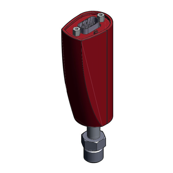
- Page 10 Dimensions [ [mm] External threa Weight ≤159 g BG 5140 (2017-09)
- Page 11 Relation Measuring signal analog - pressure Pressure p Measurement signal U p = (U / 5 V) × c (F.S.) Conversion Torr ↔ Pascal Torr 1013.25 / 760 = 101325 / 760 = 1.00 1.3332… 133.3224… Example: Gauge with 10 Torr F.S. Measurement signal U = 3 V p = (3 V / 5 V) ×...
-
Page 12: Installation
Installation WARNING: Fragile components Impacts can damage the ceramic sensor. Do not drop the product and prevent shocks. Vacuum connection DANGER: Overpressure in the vacuum system >1 bar Injury caused by released parts and harm caused by escaping process gases can result if clamps are opened while the vacuum system is pressurized. - Page 13 DANGER: Protective ground Products that are not correctly connected to ground can be extremely hazardous in the event of a fault. Electrically connect the gauge to the grounded vacuum chamber. This connection must conform to the requirements of a protective connection according to EN 61010: •...
- Page 14 Mount the gauge so that no vibrations occur. The gauge may be mounted in any orientation. To keep condensates and particles from getting into the measuring chamber preferably choose a horizontal to upright position. If adjustment should be possible after the gauge has been installed, be sure to install it so that the buttons can be accessed with a pin.
-
Page 15: Electrical Connection
Electrical connection Make sure that the gauge is properly connected to the vacuum system. The gauge may only be connected to power supplies, instruments or control devices that conform to the requirements of a grounded protective extralow voltage (PELV) and limited power source (LPS), Class 2. - Page 16 If you do not have a measurement cable, configure a measurement cable according to the following scheme. Connect the measurement cable (Cable → 8). Meas. signal Electrical connection Pin 1 Output signal (measuring signal) Pin 2 n.c. Pin 3 n.c.
-
Page 17: Operation
Operation Put the gauge in operation. Warm-up time of the gauge: approximately 1 Minute. Calibrating the gauge The gauge is factory calibrated in “standing upright” position and is maintenance-free. Installation position, long time operation and contamination can lead to a zero drift and a zero adjustment will become necessary. - Page 18 Evacuate the gauge to a pressure according to the following table: Recommended final pressure F.S. for zero adjustment <5×10 Torr <7×10 <7×10 mbar 1000 Torr 100 Torr <5×10 Torr <7×10 <7×10 mbar <5×10 Torr <7×10 <7×10 mbar 10 Torr If the final pressure is too high for a zero adjustment (>25% of F.S.), zero cannot be reached.
-
Page 19: Removal
Removal WARNING: Fragile components Impacts can damage the ceramic sensor. Do not drop the product and prevent shocks. DANGER: Contaminated parts Contaminated parts can be detrimental to health and environment. Before beginning to work, find out whether any parts are contaminated. Adhere to the relevant regulations and take the necessary precautions when handling contaminated parts. - Page 20 Caution: Dirt sensitive area Touching the product or parts thereof with bare hands increases the desorption rate. Always wear clean, lint-free gloves and use clean tools when working in this area. Vent the vacuum system. Put the gauge out of operation. ...
-
Page 21: Maintenance, Repair
Gauge failures due to contamination are not covered by the warranty. We recommend checking zero regularly. Pfeiffer Vacuum assumes no liability and the warranty becomes null and void if any repair work is carried out by the end-user or third parties. -
Page 22: Returning The Product
Contaminated products (e.g. radioactive, toxic, caustic or microbiological hazard) can be detrimental to health and environment.. Products returned to Pfeiffer Vacuum should preferably be free of harmful substances. Adhere to the forwarding regulations of all involved countries and forwarding companies and enclose a duly completed declaration of contamination *). -
Page 23: Disposing Of The Product
Disposing of the product DANGER: Contaminated parts Contaminated parts can be detrimental to health and environment. Before beginning to work, find out whether any parts are contaminated. Adhere to the relevant regulations and take the necessary precautions when handling contaminated parts. WARNING: Substances detrimental to the environment Products or parts thereof (mechanical and electric... -
Page 24: Conversion Table
Conversion table mbar Torr mm HG mbar 1×10 0.75 1×10 1×10 1×10 0.01 1×10 0.01 1×10 7.5×10 1×10 0.75 0.01 1×10 Torr 1.332 1.332×10 133.32 1.3332 0.1332 mm HG 1 Pa = 1 N/m BG 5140 BEN (2017-09) -
Page 25: Ec Declaration Of Conformity
Ceramic C Capacitance Gauge CCR 351, CC CR 352, CCR 353 Standards Harmonized an nd international / n national standards s and specifications: • EN 61000-6... - Page 26 Notes BG 5140 BEN (2017-09)
- Page 27 Notes BG 5140 BEN (2017-09)
- Page 28 VACUUM SOLUTIONS FROM A SINGLE SOURCE Pfeiffer Vacuum stands for innovative and custom vacuum solutions worldwide, technological perfection, competent advice and reliable service. COMPLETE RANGE OF PRODUCTS From a single component to complex systems: We are the only supplier of vacuum technology that provides a complete product portfolio.
Need help?
Do you have a question about the CCR 351 and is the answer not in the manual?
Questions and answers