Pfeiffer Vacuum TPG 362 Operating Instructions Manual
Singlegauge, dualgauge, single- and dual-channel measurement and control unit for activeline transmitter
Hide thumbs
Also See for TPG 362:
- Operating instructions manual (72 pages) ,
- Translation of the original instructions (40 pages)

Related Manuals for Pfeiffer Vacuum TPG 362


Summary of Contents for Pfeiffer Vacuum TPG 362
- Page 1 A P A S S I O N F O R P E R F E C T I O N TPG 361, TPG 362 SingleGauge, DualGauge Single- and Dual-Channel Measurement and Control Unit for ActiveLine Transmitter Operating Instructions...
-
Page 2: Product Identification
(→ 45). If not indicated otherwise in the legends, the illustrations in this document correspond to the unit TPG 362 (DualGauge). They apply to TPG 361 (SingleGauge) by analogy. We reserve the right to make technical changes without prior notice. -
Page 3: Intended Use
Intended Use The TPG 361 and TPG 362 are used together with Pfeiffer Vacuum ActiveLine transmitter (in this document referred to as gauges) for total pressure measure- ment. All products must be operated in accordance with their respective Operating Instructions. -
Page 4: Table Of Contents
Contents Product Identification Validity Intended Use Scope of Delivery Trademark 1 Safety 1.1 Symbols Used 1.2 Personnel Qualifications 1.3 General Safety Instructions 1.4 Liability and Warranty 2 Technical Data 3 Installation 3.1 Personnel 3.2 Installation, Setup 3.2.1 Rack Installation 3.2.2 Installation in a control panel 3.2.3 Use as Desk-Top Unit 3.3 Mains Power Connector 3.4 Gauge Connectors sensor 1, sensor 2... -
Page 5: Safety
1 Safety 1.1 Symbols Used Symbols for residual risks DANGER Information on preventing any kind of physical injury. WARNING Information on preventing extensive equipment and environmental damage. Caution Information on correct handling or use. Disregard can lead to malfunctions or minor equipment damage. -
Page 6: General Safety Instructions
EN 61010-1 Communicate the safety instructions to all other users. 1.4 Liability and Warranty Pfeiffer Vacuum assumes no liability and the warranty is rendered null and void if the end-user or third parties • disregard the information in this document •... -
Page 7: Technical Data
2 Technical Data Mains specifications Voltage 100 … 240 VAC ±10% Frequency 50 … 60 Hz Power consumption TPG 361 ≤45 VA TPG 362 ≤65 VA Overvoltage category Protection class Connection European appliance connector IEC 320 C14 Ambience Temperature storage –20 …... - Page 8 Calibration factor 0.10 … 10.00 A/D converter resolution 0.001% F.S. Switching functions Number TPG 361 TPG 362 4 (user-assignable) Reaction delay ≤10 ms, if switching threshold close to meas- urement value (for larger differences consider filter time constant). Adjustment range depending on gauge (→...
- Page 9 (→ 38) Control connector Amphenol C91B appliance connector, female, 7-pin (pin assignment → 15) Analog outputs Number TPG 361 TPG 362 2 (1 per channel) Voltage range 0 … +10 V(dc) Deviation from display value ±10 mV Output resistance <50 Ω...
- Page 10 Dimensions [mm] ≈285 70.8 68.1 55.9 ø3.5 For incorporation into a rack or control panel or as a desk-top unit Weight 1.1 kg BG 5500 BEN (2014-08) TPG36x.oi...
-
Page 11: Installation
3 Installation 3.1 Personnel Skilled personnel The unit may only be installed by persons who have suitable technical training and the necessary experience or who have been instructed by the end-user of the product. The unit is suited for incorporation into a 19" rack or a control panel or for use as a 3.2 Installation, Setup desk-top unit. -
Page 12: Installation In A Control Panel
Height 3 rack chassis adapter Secure the rack adapter in the rack frame. The maximum admissible ambient temperature (→ 7) must not be exceeded and the air circulation must not be obstructed. Rack chassis adapter Height 3 Slide the TPG 36x into the rack chassis adapter …... -
Page 13: Use As Desk-Top Unit
For reducing the mechanical strain on the front panel of the TPG 36x, preferably support the unit. Slide the TPG 36x into the cut-out of the control panel … … and secure it with four M3 or equivalent screws. 3.2.3 Use as Desk-Top Unit The TPG 36x may also be used as a desk-top unit. -
Page 14: Mains Power Connector
3.3 Mains Power Connector DANGER DANGER: line voltage Incorrectly grounded products can be extremely hazardous in the event of a fault. Use only a 3-conductor power cable with protective ground. The mains power connector may only be plugged into a socket with a protective ground. -
Page 15: Control Connector
Pin assignment Gauge connector sensor 2 is not present in TPG 361. sensor 1, sensor 2 Pin assignment of the two female 6-pin Amphenol C91B appliance connectors: Signal Identification Supply +24 V(dc) Supply common GND Signal input (measuring signal 0 … +10 V(dc)) Signal common (measuring signal–) Screening 3.5 Control Connector... -
Page 16: Relay Connector
3.6 Relay Connector This connector allows to use of the floating switching contacts for an external control system. Connect the peripheral components to the relay connector on the rear of the unit using your own, screened (electromagnetic compatibility) cable. Pin assignment, Contact positions relay Pin assignment of the female 15-pin D-Sub... -
Page 17: Interface Connector Rs485
3.7 Interface Connector The RS485 interface allows for operating the TPG 36x via a HOST or terminal RS485 (→ [19]). Integration into a bus system is possible with the use of a Y distributor. Connect the serial interface to the RS485 connector on the rear of the unit using a screened (electromagnetic compatibility) cable. -
Page 18: Interface Connector Ethernet
Pin assignment USB Type A Pin assignment of the 4-pin USB Type A appliance connector: Signal VBUS (5 V) 3.10 Interface Connector The ethernet interface allows direct communication with the TPG 36x via a computer. Ethernet Connect the ethernet cable to the connector on the rear of the unit. -
Page 19: Operation
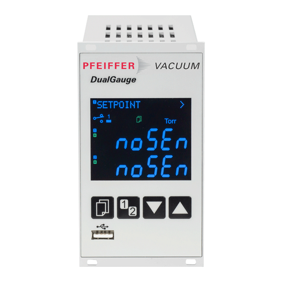
4 Operation 4.1 Front panel TPG 361 TPG 362 Display Operator keys connector Display TPG 36x Parameter or bar graph Schaltpunkte, Parametermenü, Set points, parameter mode, Pressure unit or voltage Eingabesperre keylock Status measurement channel 1 Measurement channel 1: Measurement value in... -
Page 20: Turning The Tpg 36X On And Off
Bar graph with set point measurement channel 1 Measurement channel 2 Pressure vs. time, trend measurement channel 1 Measurement channel 2 Set points 1 … 4 Parameter mode activated Set points, parameter mode, keylock Relay on Relay off Keylock on Measurement channel Measurement channel Error... -
Page 21: Operating Modes
4.3 Operating Modes The TPG 36x works in the following operating modes: • Measurement mode for displaying measurement values or statuses (→ 22) • Parameter mode for displaying and editing parameters (→ 24) − Switching function parameter group SETPOINT >... -
Page 22: Measurement Mode
Adjusting bar graph If required a bar graph may be displayed (→ 42). Changing measurement The unit alternates between measurement channels one channel (TPG 362 only) and two. The number of the selected measurement channel lights up. Turning the gauge on/off... - Page 23 Measurement range If the unit is operated with linear gauges (CMR 261 … 375, APR 250 … 267), negative pressures may be indicated. Possible causes: • negative drift • activated offset correction. Displaying the gauge Press keys for >0.5 … 1 s: identification For the measurement channel in question the type of the connected gauge is automatically identified and...
-
Page 24: Parameter Mode
4.5 Parameter Mode The Parameter mode is used for displaying, editing and entering parameter values as well as for testing the TPG 36x and for saving measurement data. For ease of operation the individual parameters are divided into groups. Unit switches from measurement mode to para- meter mode. -
Page 25: Switching Function Parameters
One level back < The TPG 361 has two, and the TPG 362 four, switching functions with two adjust- able thresholds each. The status of the switching functions is displayed on the front panel (→ 19, 15) and can be evaluated via the floating contacts at the relay connector. - Page 26 Selecting a parameter The name of the parameter and the currently valid parameter value are displayed. e.g.: SP1-CH DISABLED Switching function 1 turned off Select parameter. The value flashes and can now be edited. Editing and saving the ...
-
Page 27: Gauge Parameters
-4 *) 5×10 1500 Sx TPR/PCR IKR 2x1: 1×10 IKR 36x: 1×10 1×10 Sx IKR IKR 270: 1×10 1×10 1000 Sx PKR 1×10 1000 Sx IMR 5×10 1000 Sx PBR F.S. / 1000 Sx CMR/APR all values in hPa, GAS=nitrogen 5×10 hPa, if RNE-EXT is activated (→... - Page 28 Parameters in this group Cleaning the electrode system. DEGAS Measurement range linear gauges. Measurement value filter. FILTER Offset correction. OFFSET Calibration factor for other gases. Offset correction. Display resolution. DIGITS One level back. < Selecting a parameter The name of the parameter and the currently valid parameter value are displayed.
- Page 29 Value DEGAS Normal operation (Degas blocked) DEGAS OFF Degas: The electron collection grid is DEGAS ON heated to ≈700 °C by electron bombardment and the electrode system is thus cleaned. Duration = 180 s. Editing and saving a ...
- Page 30 Measurement value filter The measurement value filter permits a better evaluation of unstable or disturbed measuring signals. The measurement value filter does not affect the analog output (→ 15). Value FILTER No measurement value filter FILTER OFF Fast: FILTER FAST The TPG 36x responds quickly to fluctua- tions in the measurement value.
- Page 31 Offset correction The offset value is displayed and readjusted according to the actual measurement value. Available for the following gauges: Pirani & Pirani Capacitance Gauge (TPR/PCR) Cold Cathode Gauge (IKR) ® FullRange CC Gauge (PKR) Process Ion Gauge (IMR) ®...
- Page 32 Calibration factor GAS The calibration factor GAS allows • the measured value to be calibrated for the preset gases N , Ar, H , He, Ne, Kr and Xe, or • manual input of the correction factor for other gases (COR). →...
- Page 33 Calibration factor COR The calibration factor COR allows the measured value to be calibrated for other gases (→ characteristic curve in [1] … [14]). Precondition: Parameter "GAS COR" set. This parameter is not available with the measurement unit: Volt. Available for the following gauges: ...
-
Page 34: Gauge Control
4.5.3 Gauge Control The sensor control group is used for displaying, SENSOR-CONTROL > entering and editing parameters which define how the connected gauges are activated/deactivated. If the connected gauges cannot be controlled (→ 35), this group is not available. Parameters in this group Gauge activation S-ON... - Page 35 Gauge deactivation → 36. Automatic activation: S-ON CH 1 The gauge is activated by one of the (TPG 362 only) following gauges connected to measure- ment channel 1: Pirani & Pirani Capacitance Gauge (TPR/PCR) ...
- Page 36 ON threshold Definition of the ON threshold for the gauge to be activated by a gauge connected (TPG 362 only) to the other measurement channel. Available for the following following gauges: Pirani & Pirani Capacitance Gauge (TPR/PCR) Cold Cathode Gauge (IKR) ®...
- Page 37 (→ 38). Cold Cathode Gauge) Automatic deactivation: S-OFF CH 1 The gauge is deactivated by one of the (only TPG 362) following gauges connected to measurement channel 1: Pirani & Pirani Capacitance Gauge (TPR/PCR) Cold Cathode Gauge (IKR) ®...
- Page 38 Save change and return to read mode. OFF threshold Definition of the OFF threshold for the gauge to be deactivated by a gauge (TPG 362 only) connected to the other measurement channel or by itself. Available for the followingi gauges: ...
-
Page 39: General Parameters
4.5.4 General Parameters The General parameters group is used for displaying, GENERAL > entering and editing generally applicable system para- meters. Parameters in this group Measurement unit UNIT Transmission rate USB interface BAUD USB Pirani range extension RNG-EXT Error relay ERR-RELAY Penning underrange PE-UR... - Page 40 Measurement unit Unit of measured values, thresholds etc. See Appendix for conversion table (→ 56). Value UNIT mBar UNIT MBAR hPa (factory setting) UNIT HPASCAL Torr (only available if Torr lock is not UNIT TORR activated → 46) ...
- Page 41 Error sensor 1 and unit error ERR-RELAY CH 1 Error sensor 2 and unit error (only ERR-RELAY CH 2 TPG 362) Underrange control Definition of behaviour in the event of an underrange with Cold Cathode Gauges (Penning underrange control).
- Page 42 Bar graph In the dot matrix a bar graph or the measured pressure as a function of time (p = f ) may be shown. During parameter setting the parameter and the parameter value may be displayed in place of this. Value BARGRAPH ...
- Page 43 1 … 24 ADDRESS 24 Protocol Protocol serial interface (RS485, USB B, ethernet). Value PROTOCOL automatic recognition (factory PROTOCOL AUTO setting) Pfeiffer Vacuum protocol PROTOCOL PV mnemonics protocol PROTOCOL MNE Backlight Value BACKLIGHT e.g. Factory setting BACKLIGHT 60% Adjustable from 0 …...
- Page 44 Default parameter settings All user parameter settings are replaced by the default values (factory settings). Loading of the default parameter settings is irreversible. Value DEFAULT DEFAULT + 2s Press keys at the same time for >2 s to start loading default values ...
-
Page 45: Test Parameters
The value is increased/decreased by the defined parameter increments. Save change and return to read mode. Firmware version The firmware version (program version) is displayed. Version e.g. This information is helpful when contacting SOFTWARE 010100 Pfeiffer Vacuum BG 5500 BEN (2014-08) TPG36x.oi... - Page 46 Hardware version The hardware version is displayed. Hardware e.g. This information is helpful when contacting HARDWARE 010100 Pfeiffer Vacuum Operating hours The operating hours are displayed. Hours e.g. Operating hours RUNHOURS 24 h Watchdog control Behaviour of the system control (watchdog control) in the event of an error.
- Page 47 Test completed, error found. After the test, FLASH ERROR an 8-digit checksum (e.g. FLASH ) is displayed. 0x12345678 If the error persists after repeating the test, please contact your nearest Pfeiffer Vacuum service center. EEPROM test Test of the parameter memory. Test sequence EEPROM + Press keys at the same time to start test ...
-
Page 48: Data Logger Mode
Not all USB memory sticks are automatically recognized by the TPG 36x, as they (in particular cheaper brands) do not always conform to USB standard requirements. Try a different memory stick before contacting your nearest Pfeiffer Vacuum service center. Parameters in this group Current date... - Page 49 Selecting a parameter The name of the parameter and the currently valid parameter value are displayed. e.g.: INTERVAL 1s Display interval Select parameter. The value flashes and can now be edited. Editing and saving a The value is increased/decreased by the defined parameter increments.
-
Page 50: Setup Mode
File name Value Name of the measurement data file, max. FILENAME 7 digits e.g. File ending: CSV FILENAME DATALOG Start / Stop Starting / stopping measurement value display. The number of the respective measurement channel ( , ) flashes during measurement data display. - Page 51 Selecting a parameter The name of the parameter and the currently valid parameter value are displayed. e.g.: SAVE SETUP Saving all parameters Select parameter. The value flashes and can now be edited. Editing and saving a The value is increased/decreased by the defined parameter increments.
- Page 52 Formatting Formatting USB memory stick. Value FORMAT + Press keys at the same time to start formatting Formatting in progress FORMAT RUNNING Formatting completed FORMAT DONE Deleting Deleting all parameter files (ending CSV) from the USB memory stick. Value CLEAR +...
-
Page 53: Maintenance
The product contains a battery (type CR2032, service life >10 years) in order to maintain the data integrity of the real-time clock. Battery replacement is necessary if the real-time clock repeatedly shows an incorrect date. Please contact your local Pfeiffer Vacuum service center. BG 5500 BEN (2014-08) -
Page 54: Troubleshooting
A/D ERROR Acknowledge with the key. Technical support If the problem persists after the message has been acknowledged several times and/or the gauge has been exchanged, please contact your nearest Pfeiffer Vacuum service center. BG 5500 BEN (2014-08) TPG36x.oi... -
Page 55: Repair
7 Repair Return defective products to your nearest Pfeiffer Vacuum service center for repair. Pfeiffer Vacuum assumes no liability and the warranty is rendered null and void if repair work is carried out by the end-user or by third parties. -
Page 56: Appendix
Appendix ConversionTables Weights slug 2.205 68.522×10 35.274 0.454 31.081×10 slug 14.594 32.174 514.785 28.349×10 62.5×10 1.943×10 Pressures , Pa mBar, hPa Torr , Pa 10×10 10×10 7.5×10 9.869×10 100×10 750.062 0.987 mBar, hPa 100 750.062×10 0.987×10 Torr 133.322 1.333×10 1.333 1.316×10 101.325×10 1.013... -
Page 57: B: Firmware Update
Firmware Update If your TPG 36x firmware needs updating, e.g. for implementing a new gauge type, please contact your nearest Pfeiffer Vacuum service center. A firmware update is possible • via a USB memory stick (type A connector on the front of the unit), or •... - Page 58 Start USB UpdateTool, select the COM interface from the menu and click on <Connect>. Successfully connected Click on <Release Notes> to view the software release notes. BG 5500 BEN (2014-08) TPG36x.oi...
- Page 59 Click on <Manage Firmware>, select firmware … • Option <Load from disk>: Download a copy of the firmware from our website www.pfeiffer-vacuum.com. Then, select the appropriate folder. • Option <Load from server>: The update tool connects to the internet. Select the desired firmware version from the selection list.
-
Page 60: C: Ethernet Configuration
(e.g. terminal program, LabView, etc.). Depending on the protocol setting (→ 43), communication with the unit occurs with the Mnemonic or Pfeiffer Vacuum Protocol. Precondition: Windows 7 or 8 operating system (does not work under Windows XP) ... - Page 61 Automatic or manual network setting occurs in the <Network Settings> register. Automatic network setting (DHCP server required) Manual network setting In the <Virtual Serial Port> register a specific COM Port can be assigned to each device, and/or … BG 5500 BEN (2014-08) TPG36x.oi...
-
Page 62: D: Literature
… a new COM Port can be created. Literature [1] www.pfeiffer-vacuum.com Instruction Sheet Compact Pirani Gauge TPR 261 BG 5105 BEN Pfeiffer Vacuum GmbH, D–35614 Asslar, Germany [2] www.pfeiffer-vacuum.com Instruction Sheet Compact Pirani Gauge TPR 265 BG 5177 BEN Pfeiffer Vacuum GmbH, D–35614 Asslar, Germany ... - Page 63 [9] www.pfeiffer-vacuum.com Instruction Sheet Compact Cold Cathode Gauge IKR 270 BG 5115 BEN Pfeiffer Vacuum GmbH, D–35614 Asslar, Germany [10] www.pfeiffer-vacuum.com Operating Instructions Compact Cold Cathode Gauge IKR 360, IKR 361 ® Compact FullRange Gauge PKR 360, PKR 361 BG 5164 BEN Pfeiffer Vacuum GmbH, D–35614 Asslar, Germany...
-
Page 64: Etl Certification
ETL Certification ETL LISTED The products TPG 361 and TPG 362 • conform to the UL Standards UL 61010-1 and UL 61010-2-030 • are certified to the CAN/CSA Standards C22.2 No. 61010-1-12 and C22.2 No. 61010-2-030 4010094 BG 5500 BEN (2014-08) TPG36x.oi... -
Page 65: Ec Declaration Of Conformity
EC Declaration of Conformity We, Pfeiffer Vacuum, hereby declare that the equipment mentioned below com- plies with the provisions of the Directive relating to electrical equipment designed for use within certain voltage limits 2006/95/EC, the Directive relating to electro- magnetic compatibility 2004/108/EC and the Directive on the restriction of the use of certain hazardous substances in electrical and electronic equipment 2011/65/EU. - Page 66 Notes BG 5500 BEN (2014-08) TPG36x.oi...
- Page 67 Notes BG 5500 BEN (2014-08) TPG36x.oi...
- Page 68 A P A S S I O N F O R P E R F E C T I O N Vacuum solutions Pfeiffer Vacuum stands for innovative and custom from a single source vacuum solutions worldwide, technological perfection, competent advice and reliable service.
Need help?
Do you have a question about the TPG 362 and is the answer not in the manual?
Questions and answers
how to fix zero Torr
The provided context does not contain specific instructions for fixing a zero Torr issue on the Pfeiffer Vacuum TPG 362. However, you can try the following general troubleshooting steps:
1. Check Sensor Connection – Ensure the gauge sensor is properly connected to the Amphenol C91B appliance connector.
2. Verify Compatible Gauge – Confirm that the connected gauge is compatible (e.g., Pirani TPR 261, TPR 265, TPR 280, TPR 281, or Pirani Capacitance PCR).
3. Inspect Power Supply – Ensure the device is receiving the correct voltage (100–240 VAC, 50–60 Hz).
4. Check for Firmware Updates – If necessary, contact Pfeiffer Vacuum service for a firmware update.
5. Look for Damage or Contamination – Inspect the sensor for contamination or damage and clean or replace it if needed.
6. Ensure Proper Operating Conditions – Verify that the unit is operating within the specified temperature (5–50°C) and humidity limits (≤80% at 31°C).
If the issue persists, contacting Pfeiffer Vacuum support is recommended.
This answer is automatically generated