Advertisement
Quick Links
Advertisement

Related Manuals for Enwork Cayman CM1001


Summary of Contents for Enwork Cayman CM1001
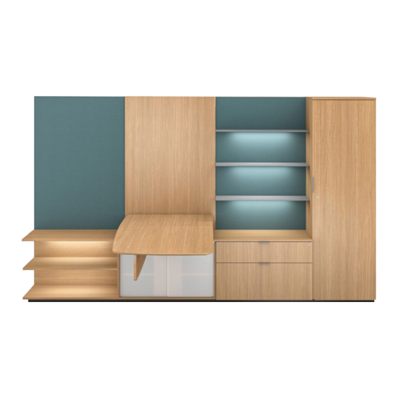
- Page 1 Cayman Installation Guide CM1001 Cayman Installation Guide – Rev 10.23.23...
-
Page 2: Tools And Supplies Required
TOOLS & SUPPLIES REQUIRED DRILL DRILL BIT SET PHILLIPS HEAD DRIVER HEX HEAD DRIVER SQUARE HEAD DRIVER LEVEL MARKER TAPE MEASURE RATCHET SOCKET SET CM1001 - Cayman Installation Guide... - Page 3 INCLUDED PARTS AND FASTENERS (component, size, and quantity may vary depending on Typical) (A) 1/4-20 X 3/4" (B) 3/8 X 2" HEX LAG BOLT (C) 5/16 X 7/8" (D) M8 X 25MM HEX HEAD BOLT HEX SERR FLANGE BOLT HEX SERR FLANGE BOLT (E) HAFELE BUTTON FIX (F) 1/2 DIA X 1/8"...
- Page 4 INCLUDED PARTS AND FASTENERS (component, size, and quantity may vary depending on Typical) M10 X 1.5 X 20MM LEVELER (Q) USPT JOINER PLATE CABINET SUPPORT POST CABINET SUPPORT POST/WALL SUGATSUNE TG-40 (CMM-2001-X) CONNECTION BRACKET (CMM-1045) WALL SUPPORT ANCHOR WALL ANCHOR CONNECTION COLUMN GROMMET CANTILEVER WELDMENT (CMM-1041)
- Page 5 ASSEMPLY OPTIONS (all Typicals shown below are RH configurations; LH will be reversed) A – ADD ON MODULE WORK WALL (OPTIONAL SHELVES) B – ADD ON MODULE LOWER CABINET C – RETURN LOWER CABINET K – CANTILEVER (FIXED OR ADJUSTABLE) Q –...
- Page 6 1 — PLINTH INSTALL ATION FIG 1.1 (SINGLE PIECE PLINTH) FIG 1.2 (MULTI-PIECE PLINTH) Install levelers into the plinth. Install and tighten (O) ZIPBOLT TIGHT JOINT CONNECTORS (2 per seam) to the top side of the plinth. Note: Extra (T) M10 x 13mm insert included with the hardware. Once secured and tightened, Flip the plinth and install (Q) USPT Joiner Plates (2 per seam) to the underside of the plinth using (L) #8 x 3/4"...
- Page 7 2 — CASE ASSEMBLY FIG 2.1 (CASE PLACEMENT) FIG 2.2 (CASE PLACEMENT) Tip: For easier assembly, remove all case doors, drawers and any Cantilever Refer to product labels and page 5 for component location. Case removable panels. Removeable panels are labeled with stickers. To be reassembled later.
- Page 8 2 — CASE ASSEMBLY, 3 — POST TO WALL ATTACHMENT FIG 2.5 (CASE TO PLINTH ATTACHMENT) FIG 3.1 (CABINET SUPPORT POST ATTACHMENT) Attach the cabinets to the plinth using (I) #8 x 1-1/4" Phillips Pan Head wood Pull the case and plinth subassembly away from the wall to access the screws starting with the cantilever case (if present).
- Page 9 3 — POST TO WALL ATTACHMENT FIG 3.4 (WALL SUPPORT ANCHOR) FIG 3.5 (POST TO WALL ATTACHMENT) Install the Wall Support Anchor bolt approximately 19" off of floor. Confirm Loosely attach the Cabinet Support Post/Wall Connection Brackets height of preinstalled connection bracket on back of cantilever cabinet (see (L-brackets) to the outer most Cabinet Support Posts using (C) 5/16 x 7/8"...
- Page 10 4 — TOWER ATTACHMENT, 5 — WALL ATTACHMENT, 6 — TOP ATTACHMENT FIG 4.1 (TOWER ATTACHMENT) FIG 5.1 (WALL ATTACHMENT) Locate and attach the Tower to the plinth and the adjoining case using Locate the wall panel that will be at the end of the installation. Install the (E) the predrilled holes and 9x (I) #10 x 1-1/4"...
- Page 11 6 — TOP ATTACHMENT FIG 6.3 (TABLE COLUMN) FIG 6.4 (OPTIONAL UTILITY TRAY) Attach the Cantilever Weldment to either the height-adjustable or fixed height Install the Power Unit into the Utility Tray using the screws provided column using 4x (D) M8 x 25mm Hex Head bolts. with the unit.
- Page 12 6 — TOP ATTACHMENT, 7 — MODEST Y PANEL ATTACHMENT, 8 — FILLER PANEL ATTACHMENT FIG 6.7 (CANTILEVER INSTALLATION) FIG 7.1 (OPTIONAL LAMINATE MODESTY PANEL) Install Weldment Cover Panel by hooking the front edge over the Cantilever Attach 3x Modesty Panel Mounting Brackets to the Laminate Modesty Panel Weldment and engaging the magnets.
- Page 13 8 — FILLER PANEL ATTACHMENT, 9 — OVERHEAD STOR AGE ATTACHMENT FIG 8.2 (FILLER PANEL ADJUSTMENT) FIG 9.1 (OVERHEAD STORAGE ATTACHMENT) Review Edge Trim Panel fit. If needed, the Edge Trim may be adjusted using Overhead storage case can be installed over the top edge of the wall panel the (C) 5/16 x 7/8"...
- Page 14 10 — HEIGHT-ADJUSTABLE HANDSET FIG 10.1 (SETTING THE LED RETRACTED HEIGHT) Press the DOWN button on the Handset until the base reaches its lowest position. Measure the distance from floor to the top surface of the desktop. If the number on the LED display does NOT match your measurement, follow these steps: Press and hold the DOWN button until the LED display reads "RST".
- Page 15 Cayman Freestanding Installation Addendum CM1001 Cayman Free Standing Installation Addendum...
- Page 16 TOOLS & SUPPLIES REQUIRED, INCLUDED PARTS & FASTENERS DRILL DRILL BIT SET RATCHET SOCKET SET PANEL MOUNTING BRACKET #8 X .75" .375 X 5" CONCRETE ANCHOR (CMM-1044) PHILLIPS PAN HEAD (MCMASTER-CARR 97110A203) CM1001 - Cayman Installation Guide...
-
Page 17: Freestanding Installation
1 — FREESTANDING INSTALL ATION FIG 1.1 FIG 1.2 Freestanding application requires the addition of 2x CMM-1044 Mounting Cayman unit must be level and in its final location. Brackets to the cabinet directly next to the Cantilever Cabinet. FIG 1.3 FIG 1.4 Locate the 3x 3/8"... - Page 18 1 — FREESTANDING INSTALL ATION FIG 1.5 Anchor the case using 3x .375 x 5" Concrete Stud Anchor. Ensure the anchor has a minimum of 1-3/4" of engagement. Tighten the bolts to 25ft-lbs. CM1001 - Cayman Installation Guide...
- Page 19 Cayman LED Light Installation Guide Addendum CM1001 Cayman LED Light Installation Guide Addendum...
- Page 20 INCLUDED PARTS AND FASTENERS (Component, Size, and Quantities May Vary Dependent on Typical) POWER SUPPLY POWER CORD 12V POWER SUPPLY SPLITTER DIMMER SWITCH LED LIGHT CM1001 - Cayman Installation Guide...
- Page 21 1 — LIGHTING ASSEMBLY STEPS FIG 1.1 FIG 1.2 Route the Dimmer Switch wires through the case and out the back Connect the (A) Power Supply Power Cord to the (B) Power Supply. of the case. DO NOT connect to the Power Supply to the Power Strip in the Cayman unit.
- Page 22 3 — LIGHTING ASSEMBLY STEPS FIG 1.5 FIG 1.6 Connect an (E) LED Light Strip (female) to any of the (D) Splitter Additional (E) LED Light Strips may be connected to the any open connector leads (male). leads of the (D) Splitter. All lights will be operated by the (C) Dimmer Switch.
- Page 23 800.815.7251 enwork.com 12900 Christopher Drive Lowell, MI 49331 Specifications subject to change without notice.
Need help?
Do you have a question about the Cayman CM1001 and is the answer not in the manual?
Questions and answers