Table of Contents
Advertisement
Quick Links
Table of contents
Assembly & Operating Instructions
Compact Rotary Modules
Translation of the Original Assembly Instructions EN
CR 12
Order no.: 50112939
◼
CR 12-ZA
Order no.: 50112940
◼
CR 16
Order no.: 50112941
◼
CR 16-ZA
Order no.: 50112942
◼
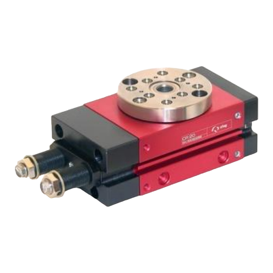
CR 20
Order no.: 50112943
◼
CR 20-ZA
Order no.: 50112945
◼
Assembly instructions EN
CR 12
I
CR 16
◼
CR 12 I CR 16 I CR 20
I
CR 20
◼
◼
12.06.2023
V4.0
1–59
Advertisement
Table of Contents

Related Manuals for Afag CR 20-ZA


Summary of Contents for Afag CR 20-ZA
- Page 1 Order no.: 50112941 ◼ CR 16-ZA Order no.: 50112942 ◼ CR 20 Order no.: 50112943 ◼ CR 20-ZA Order no.: 50112945 ◼ ◼ ◼ ◼ Assembly instructions EN CR 12 I CR 16 I CR 20 12.06.2023 V4.0 1–59...
- Page 2 Your Afag team © Subject to modifications The rotary modules have been designed by Afag Automation AG according to the state of the art. Due to the constant technical development and improvement of our products, we reserve the right to make technical changes at any time.
-
Page 3: Table Of Contents
Table of contents Table of contents General ........................6 Contents and purpose of these assembly instructions ......... 6 Explanation of symbols................. 6 Additional symbols ..................7 Applicable documents .................. 8 Warranty ....................... 8 Liability ......................8 Safety instructions ....................9 General ...................... - Page 4 3.3.2 Technical data CR 20 ................27 3.3.3 Preferred combinations CR 20 ............. 28 3.3.4 Module loads CR 20 ................29 3.3.5 Load diagrams CR 20 ................30 Transport, Packaging and Storage ..............31 Safety instructions for transport ..............31 Scope of supply ..................
- Page 5 Table of contents Maintenance and repair ..................52 General notes ..................... 52 Safety instructions for maintenance and repair .......... 52 Maintenance activities and maintenance intervals ........53 9.3.1 Overview of the maintenance points ............ 53 9.3.2 Compressed air specifications ............. 54 9.3.3 Further maintenance ................
-
Page 6: General
General General 1.1 Contents and purpose of these assembly instructions These assembly instructions contain important information on assembly, commissioning, functioning and maintenance of the rotary modules 20 to ensure safe and efficient handling and operation. Consistent compliance with these assembly instructions will ensure: ▪... -
Page 7: Additional Symbols
General Further warning signs: Where applicable, the following standardised symbols are used in this manual to point out the various potential health risks. Warning - Dangerous electrical voltage. Warning - Risk of injury from contact with hot surfaces. Warning - Risk of hand and finger injury due to uncontrolled movements of components. -
Page 8: Applicable Documents
▪ Wear parts (e.g. shock absorbers) are excluded from the warranty.* The warranty covers the replacement or repair of defective Afag parts. Further claims are excluded. * However, a customer has a right to a defect-free product. This does also apply to defective accessories and wear parts. -
Page 9: Safety Instructions
In the chemical industry and in potentially explosive areas, the use of rotary modules is not permitted without additional safety measures. In such cases, please consult with the Afag technical department. The intended use of the module also includes: ▪ observance of all instructions given in this instructions manual, ▪... -
Page 10: Obligations Of The Operator And The Personnel
▪ the operating company shall be solely responsible for such damage, and ▪ Afag does not accept any liability for damages caused by improper use. 2.4 Obligations of the operator and the personnel 2.4.1... -
Page 11: Obligations Of The Personnel
Safety instructions 2.4.3 Obligations of the personnel All personnel working with the rotary modules are required to: ▪ read and observe these assembly instructions, especially the chapter on safety, ▪ observe the occupational safety and accident prevention regulations, ▪ observe all safety and warning signs on the rotary modules, ▪... -
Page 12: Personal Protective Equipment (Ppe)
2.7 Changes and modifications No changes may be made to the rotary modules which have not been described in these assembly instructions or approved in writing by Afag Automation AG. Afag Automation AG accepts no liability for unauthorised changes or improper assembly, installation, commissioning, maintenance or repair work. -
Page 13: General Hazards / Residual Risks
Safety instructions 2.8 General hazards / Residual Risks Despite the safe design of the machine and the technical protective measures taken, there still remain residual risks that cannot be avoided, and which present a non-obvious residual risk when operating the rotary modules. Observe the safety instructions in this chapter and in the other sections of this manual to avoid damage to property and dangerous situations for the personnel, 2.8.1... -
Page 14: Danger Due To Electricity
Safety instructions CAUTION Risk of injuries due to uncontrolled parts movements! When operating the rotary modules uncontrolled movements may occur which can cause personal injury or property damage. ▪ Only qualified personnel may work with or on the rotary modules. ▪... -
Page 15: Danger Due To Pneumatics
Safety instructions 2.8.4 Danger due to pneumatics WARNING Risks by the pneumatic system! The pneumatic system can pose various hazards that can cause serious or fatal injuries if the work is carried out improperly. ▪ Only qualified personnel may work with or on the pneumatic system! ▪... -
Page 16: Technical Data
Technical data Technical data 3.1 Rotary module CR 12 3.1.1 Dimensional drawing CR 12 Fig. 1 Dimensional drawing - Rotary module CR 12 16 – 59 ◼ ◼ ◼ Assembly instructions EN CR 12 I CR 16 I CR 20 12.06.2023 V4.0... -
Page 17: Technical Data Cr 12
Technical data 3.1.2 Technical data CR 12 Fig. 2 Table technical data CR 12 * In the end position, only half the torque is achieved, since in this position the pressure is exerted by one piston only (chapter Fehler! Verweisquelle konnte nicht gefunden werden.). -
Page 18: Preferred Combinations Cr 12
Technical data 3.1.1 Preferred combinations CR 12 18 – 59 ◼ ◼ ◼ Assembly instructions EN CR 12 I CR 16 I CR 20 12.06.2023 V4.0... -
Page 19: Module Loads Cr 12
Technical data 3.1.2 Module loads CR 12 Fig. 3 Table module loads CR 12 ◼ ◼ ◼ Assembly instructions EN CR 12 I CR 16 I CR 20 12.06.2023 V4.0 19–59... -
Page 20: Load Diagrams Cr 12
Technical data 3.1.3 Load diagrams CR 12 Fig. 4 Load diagrams CR 12 20 – 59 ◼ ◼ ◼ Assembly instructions EN CR 12 I CR 16 I CR 20 12.06.2023 V4.0... -
Page 21: Rotary Module Cr 16
Technical data 3.2 Rotary module CR 16 3.2.1 Dimensional drawing CR 16 Fig. 5 Dimensional drawing - Rotary module CR 16 ◼ ◼ ◼ Assembly instructions EN CR 12 I CR 16 I CR 20 12.06.2023 V4.0 21–59... -
Page 22: Technical Data Cr 16
Technical data 3.2.2 Technical data CR 16 Fig. 6 Table technical data CR 16 * In the end position, only half the torque is achieved, since in this position the pressure is exerted by one piston only). 22 – 59 ◼... -
Page 23: Preferred Combinations Cr 16
Technical data 3.2.3 Preferred combinations CR 16 ◼ ◼ ◼ Assembly instructions EN CR 12 I CR 16 I CR 20 12.06.2023 V4.0 23–59... -
Page 24: Module Loads Cr 16
Technical data 3.2.4 Module loads CR 16 Fig. 7 Table module loads CR 16 24 – 59 ◼ ◼ ◼ Assembly instructions EN CR 12 I CR 16 I CR 20 12.06.2023 V4.0... -
Page 25: Load Diagrams Cr 16
Technical data 3.2.5 Load diagrams CR 16 Fig. 8 Load diagrams CR 16 ◼ ◼ ◼ Assembly instructions EN CR 12 I CR 16 I CR 20 12.06.2023 V4.0 25–59... -
Page 26: Rotary Module Cr 20
Technical data 3.3 Rotary module CR 20 3.3.1 Dimensional drawing CR 20 Fig. 9 Dimensional drawing - Rotary module CR 20 26 – 59 ◼ ◼ ◼ Assembly instructions EN CR 12 I CR 16 I CR 20 12.06.2023 V4.0... -
Page 27: Technical Data Cr 20
Technical data 3.3.2 Technical data CR 20 Fig. 10 Table technical data CR 20 * In the end position, only half the torque is achieved, since in this position the pressure is exerted by one piston only). ◼ ◼ ◼ Assembly instructions EN CR 12 I CR 16 I CR 20 12.06.2023... -
Page 28: Preferred Combinations Cr 20
Technical data 3.3.3 Preferred combinations CR 20 28 – 59 ◼ ◼ ◼ Assembly instructions EN CR 12 I CR 16 I CR 20 12.06.2023 V4.0... -
Page 29: Module Loads Cr 20
Technical data 3.3.4 Module loads CR 20 Fig. 11 Table module stresses CR 20 ◼ ◼ ◼ Assembly instructions EN CR 12 I CR 16 I CR 20 12.06.2023 V4.0 29–59... -
Page 30: Load Diagrams Cr 20
Technical data 3.3.5 Load diagrams CR 20 Fig. 12 Load diagrams CR 20 30 – 59 ◼ ◼ ◼ Assembly instructions EN CR 12 I CR 16 I CR 20 12.06.2023 V4.0... -
Page 31: Transport, Packaging And Storage
Transport, Packaging and Storage Transport, Packaging and Storage This chapter provides information regarding proper transport, packaging and storage of the rotary modules. 4.1 Safety instructions for transport CAUTION Danger of injury when unpacking the rotary modules! The rotary modules are packed in the original packaging (cardboard box). If handled incorrectly, the module may fall out of the box when unpacked and cause limb injuries. -
Page 32: Transport
Transport, Packaging and Storage 4.3 Transport No liability can be assumed for damages caused by improper installation on the part of the operating company. The following conditions must be complied with for transport and storage: ▪ Storage temperature: 0-50 °C ▪... -
Page 33: Storage
Transport, Packaging and Storage 4.5 Storage If the rotary modules are stored for an extended period, observe the following: ▪ Do not store the rotary modules outdoors or expose them to weather conditions. ▪ The storage space must be dry and dust free. ▪... -
Page 34: Structure And Description
Structure and description Structure and description This chapter provides an overview of the rotary modules’ structure and functioning. 5.1 Construction rotary modules Fig. 14 Structure of the rotary module CR 1. Housing 7. Clamping plate 2. Flange 8. Lock nut for positioning pin 3. -
Page 35: Accessories
Max. Energy consumption/h 20,000 Nm Suitable for CR 16, CR 20 You will find more information on the accessories for the rotary modules on our website www.afag.com. ◼ ◼ ◼ Assembly instructions EN CR 12 I CR 16 I CR 20 12.06.2023... -
Page 36: Fields Of Application
Structure and description 5.4 Fields of application The CR rotary modules are exclusively designed for rotational movements for the following payloads ( chapter ▪ CR 12: 10 kg/cm ▪ CR 16: 70 kg/cm ▪ CR 20: 350 kg/cm In combination with other modules the rotary modules can be used as a pick &... -
Page 37: Installation, Assembly & Setting
Installation, assembly & setting Installation, assembly & setting This chapter contains specific safety instructions and information regarding proper installation, assembly and setting of the rotary modules including their connection to the control unit and the pneumatic system. 6.1 Safety instructions for installation & assembly CAUTION Danger of injury when connecting the rotary modules to the control unit and the compressed-air system! -
Page 38: Installation And Assembly
Assembly and attachment In order to ensure high and repetitive accuracy of fit during assembling, operation and exchanging of a module, the components of the Afag modules are provided with a precise module centering unit. The rotary modules can be mounted both in horizontal and vertical position. - Page 39 Installation, assembly & setting ◼ ◼ ◼ Assembly instructions EN CR 12 I CR 16 I CR 20 12.06.2023 V4.0 39–59...
-
Page 40: Tightening Torques For Screws
Installation, assembly & setting 6.2.2 Tightening torques for screws For assembling use screws with the following minimum specifications: Standard VDI 2230 Screw strength Category 8.8 Surface: Galvanized blue, oiled or greased Thread Tightening torque 1.1 … 1.4 Nm 2.6 … 3.3 Nm 5.2 …... - Page 41 Installation, assembly & setting Pneumatic connections rotary modules CR 12, CR 16 and CR 20 The CR rotation module has 5 selectable pneumatic connection options for each direction of rotation. (1) Upper module half: 5 connections, clockwise direction of rotation (2) Lower module half: 5 Connections, counterclockwise direction of rotation Fig.
-
Page 42: Assembling, Monitoring, Replacement Of The Sensors
Installation, assembly & setting Fig. 19 Pneumatic circuit diagram CR-ZA with intermediate positions 1. Compressed air connection 5. Rotary module CR 2. Maintenance unit 6. Intermediate position cylinder for CR 3. 5/3 Way-valve 7. Throttle check valve (damping intermediate pos.) 4. - Page 43 Installation, assembly & setting Installation of the sensors Proceed as follows to install the sensors: 1. Insert the sensor (Fig. 20, 1) with the mounted slot nut into the C-slot. 2. Connect the sensor to the control system. 3. Carry out a function check on the rotary module and check whether the sensor switches correctly.
-
Page 44: Settings
Installation, assembly & setting 6.3 Settings This chapter contains information on the adjustment work to be carried out on the rotary modules. NOTICE No liability can be assumed for damages caused by improper work carried out on the rotary modules on the part of the operator. 6.3.1 Safety notes for settings WARNING... -
Page 45: Adjusting The Angle Of Rotation
Installation, assembly & setting 6.3.2 Adjusting the angle of rotation Fig. 22 Example illustration 1. Shock absorber 5. Clamping screw 2. Lock nut 6. Rotary flange 3. Seal 7. Compr. air connection P2 (clockwise) 4. Stop sleeve 8. Compressed air connection P1 (counterclockwise) Angle of rotation Maximum rotation angle = 180°... -
Page 46: Setting Of The End Positions
Installation, assembly & setting 6.3.3 Setting of the end positions The exact setting of an end position depends on the stop sleeve, the shock absorber and the adjusted compressed air. To set the end positions proceed as follows: 1. Compressed air at P1: Flange rotates clockwise. 2. -
Page 47: Adjusting The Shock Absorber
Installation, assembly & setting 6.3.5 Adjusting the shock absorber Maximum damping effect The maximum damping effect is achieved when the shock absorbers are fully screwed into the stop sleeve (mechanical stopper). Shock absorbers Shock screwed in absorbers screwed in Reduced damping effect The damping effect is reduced by turning back the shock absorbers. -
Page 48: Setting Of Intermediate Positions
Installation, assembly & setting 6.3.6 Setting of intermediate positions Legend Retracted Lock nut Positioning pin 1 Positioning pin 2 extended Intermediate positions With the intermediate stop module ZA, up to two intermediate positions can be approached. Adjustment range of the intermediate position(s) The maximum setting range is 60°... -
Page 49: Approaching The Intermediate Positions
Installation, assembly & setting 6.3.7 Approaching the intermediate positions Position -90° -15° +20° +90° *P1, P2, P3=Air connections 0=unpressurised 1=pressurised Fig. 23 Positions (example illustration) ◼ ◼ ◼ Assembly instructions EN CR 12 I CR 16 I CR 20 12.06.2023 V4.0 49–59... -
Page 50: Commissioning
Commissioning Commissioning This chapter contains information on how to commission the rotary modules. After connection to the pneumatic system and mounting of the sensors, the rotary modules are commissioned for the first time via the system control. 7.1 Safety instructions for commissioning CAUTION Danger of injury by moving components! Limbs can be crushed by moving components! -
Page 51: Fault Elimination
8.3 Table Fault causes and remedy The following table contains an overview of possible fault causes and how to proceed to eliminate them. Defective components must be replaced exclusively by Afag original spare parts. 8.3.1 Troubleshooting table Fault Possible cause Remedy: ▪... -
Page 52: Maintenance And Repair
Maintenance and repair Maintenance and repair 9.1 General notes The rotary modules are almost maintenance-free. Nevertheless, some maintenance work must be carried out to ensure an optimum operating condition of the modules. This chapter describes the required maintenance activities. Each rotary module is accompanied by a safety information sheet. This information sheet must be read carefully by every person who carries out work on and with the rotary module. -
Page 53: Maintenance Activities And Maintenance Intervals
Maintenance and repair 9.3 Maintenance activities and maintenance intervals The rotary modules are almost maintenance-free. Nevertheless, some maintenance work must be carried out to ensure an optimum operating condition of the rotary modules. 9.3.1 Overview of the maintenance points Fig. 24 Maintenance points rotary module System Interval... -
Page 54: Compressed Air Specifications
If the rotary modules are used in an ionised air environment, there is a risk that exposed parts could corrode. ▪ Always grease exposed parts e.g. flanges, shafts, guides and jaws regularly. ▪ Afag standard lubrication: Staburax NBU8EP (flat guides), Blasolube 301 (piston rods) 9.3.2 Compressed air specifications The rotary modules are lifetime lubricated and can be operated with lubricated or non-lubricated compressed air. -
Page 55: Further Maintenance
Afag for warranty repair within the warranty period. After the warranty period has expired, the customer can replace or repair defective modules or wear parts himself or send them to the Afag repair service. Please note that Afag does not assume any warranty for modules that have... -
Page 56: Decommissioning, Disassembly, Disposal
Decommissioning, disassembly, disposal 10 Decommissioning, disassembly, disposal The rotary modules must be properly dismantled after use and disposed of in an environmentally friendly manner. 10.1 Safety instructions for decommissioning, disassembling and disposal WARNING Risk of injury due to improper decommissioning, disassembly and disposal! Improperly carried out activities can result in considerable material damage and serious injury. -
Page 57: Disposal
Decommissioning, disassembly, disposal 10.4 Disposal The rotary modules must be disposed of properly at the end of their service life and the raw materials used must be recycled. Observe the legal regulations and company requirements. The rotary modules must not be disposed of as a complete unit. Dismantle the rotary module into individual parts and separate the various components according to type of material and dispose of them properly: ▪... -
Page 58: Declaration Of Incorporation
The relevant technical documentation has been created according to Annex VII, Part B of the above- mentioned Directive. Authorised representative for compiling the technical documentation: Niklaus Röthlisberger, Product Manager, Afag Automation AG, CH-6144 Zell Zell, 31.05.2023 Adrian Fuchser Klaus Bott... - Page 59 Afag Automation Americas Afag Automation APAC Schaeff Machinery & Services LLC. Afag Automation Technology (Shanghai) Co., Ltd. 883 Seven Oaks Blvd, Suite 800 Room 102, 1/F, Bldg. 56, City Of Elite Smyrna, TN 37167 No.1000, Jinhai Road, Pudong New District...
Need help?
Do you have a question about the CR 20-ZA and is the answer not in the manual?
Questions and answers